DE102017112552B4 - ANTENNA WITH MULTIPLE INDIVIDUAL RADIATORS - Google Patents
ANTENNA WITH MULTIPLE INDIVIDUAL RADIATORS Download PDFInfo
- Publication number
- DE102017112552B4 DE102017112552B4 DE102017112552.3A DE102017112552A DE102017112552B4 DE 102017112552 B4 DE102017112552 B4 DE 102017112552B4 DE 102017112552 A DE102017112552 A DE 102017112552A DE 102017112552 B4 DE102017112552 B4 DE 102017112552B4
- Authority
- DE
- Germany
- Prior art keywords
- antenna
- individual radiators
- radiators
- individual
- partition walls
- Prior art date
- Legal status (The legal status is an assumption and is not a legal conclusion. Google has not performed a legal analysis and makes no representation as to the accuracy of the status listed.)
- Active
Links
Images
Classifications
-
- H—ELECTRICITY
- H01—ELECTRIC ELEMENTS
- H01Q—ANTENNAS, i.e. RADIO AERIALS
- H01Q21/00—Antenna arrays or systems
- H01Q21/06—Arrays of individually energised antenna units similarly polarised and spaced apart
- H01Q21/061—Two dimensional planar arrays
- H01Q21/064—Two dimensional planar arrays using horn or slot aerials
-
- H—ELECTRICITY
- H01—ELECTRIC ELEMENTS
- H01Q—ANTENNAS, i.e. RADIO AERIALS
- H01Q1/00—Details of, or arrangements associated with, antennas
- H01Q1/52—Means for reducing coupling between antennas; Means for reducing coupling between an antenna and another structure
- H01Q1/521—Means for reducing coupling between antennas; Means for reducing coupling between an antenna and another structure reducing the coupling between adjacent antennas
- H01Q1/523—Means for reducing coupling between antennas; Means for reducing coupling between an antenna and another structure reducing the coupling between adjacent antennas between antennas of an array
-
- H—ELECTRICITY
- H01—ELECTRIC ELEMENTS
- H01Q—ANTENNAS, i.e. RADIO AERIALS
- H01Q13/00—Waveguide horns or mouths; Slot antennas; Leaky-waveguide antennas; Equivalent structures causing radiation along the transmission path of a guided wave
- H01Q13/06—Waveguide mouths
-
- H—ELECTRICITY
- H01—ELECTRIC ELEMENTS
- H01Q—ANTENNAS, i.e. RADIO AERIALS
- H01Q3/00—Arrangements for changing or varying the orientation or the shape of the directional pattern of the waves radiated from an antenna or antenna system
- H01Q3/02—Arrangements for changing or varying the orientation or the shape of the directional pattern of the waves radiated from an antenna or antenna system using mechanical movement of antenna or antenna system as a whole
- H01Q3/04—Arrangements for changing or varying the orientation or the shape of the directional pattern of the waves radiated from an antenna or antenna system using mechanical movement of antenna or antenna system as a whole for varying one co-ordinate of the orientation
-
- H—ELECTRICITY
- H01—ELECTRIC ELEMENTS
- H01Q—ANTENNAS, i.e. RADIO AERIALS
- H01Q3/00—Arrangements for changing or varying the orientation or the shape of the directional pattern of the waves radiated from an antenna or antenna system
- H01Q3/26—Arrangements for changing or varying the orientation or the shape of the directional pattern of the waves radiated from an antenna or antenna system varying the relative phase or relative amplitude of energisation between two or more active radiating elements; varying the distribution of energy across a radiating aperture
- H01Q3/30—Arrangements for changing or varying the orientation or the shape of the directional pattern of the waves radiated from an antenna or antenna system varying the relative phase or relative amplitude of energisation between two or more active radiating elements; varying the distribution of energy across a radiating aperture varying the relative phase between the radiating elements of an array
- H01Q3/34—Arrangements for changing or varying the orientation or the shape of the directional pattern of the waves radiated from an antenna or antenna system varying the relative phase or relative amplitude of energisation between two or more active radiating elements; varying the distribution of energy across a radiating aperture varying the relative phase between the radiating elements of an array by electrical means
Landscapes
- Variable-Direction Aerials And Aerial Arrays (AREA)
- Waveguide Aerials (AREA)
Abstract
Antenne
• mit mehreren Einzelstrahlern (1), die in x- und y-Richtung ein Antennenfeld mit einer Apertur bilden,
• wobei die Einzelstrahler (1) jeweils durch eine Trennwand (2, 21, 22) voneinander getrennt sind, und
• zumindest ein Teil der Trennwände (2, 21, 22) eine aus der Apertur herausstehende Störstelle (3) aufweist, dadurch gekennzeichnet, dass die Einzelstrahler (1) offene Rundhohlleiter sind, sich die Trennwände (21) in x-Richtung von den Trennwänden (22) in y-Richtung bezüglich der Wandstärke (d) unterscheiden, und Einzelstrahler (1) in x-Richtung einen Abstand von kleiner λ aufweisen und Einzelstrahler (1) in y-Richtung eine Lamellenstruktur (4) in der Trennwand (22) aufweisen.
• with several individual radiators (1) which form an antenna field with an aperture in the x and y directions,
• wherein the individual radiators (1) are each separated from one another by a partition wall (2, 21, 22), and
• at least some of the partition walls (2, 21, 22) have an impurity (3) protruding from the aperture, characterized in that the individual radiators (1) are open circular waveguides, the partition walls (21) in the x-direction differ from the partition walls (22) in the y-direction with regard to the wall thickness (d), and individual radiators (1) in the x-direction have a distance of less than λ and individual radiators (1) in the y-direction have a lamellar structure (4) in the partition wall (22).
Description
Technisches Gebiettechnical field
Die vorliegende Erfindung betrifft eine Antenne mit mehreren Einzelstrahlern. Solche Antennen werden beispielsweise für die aeronautische Satellitenkommunikation im Ku- und Ka-Band benötigt.The present invention relates to an antenna with several individual radiators. Such antennas are required, for example, for aeronautical satellite communications in the Ku and Ka bands.
Stand der TechnikState of the art
Der Bedarf an drahtlosen Breitbandkanälen zur Datenübertragung mit sehr hohen Datenraten, insbesondere im Bereich der aeronautischen, d.h. flugzeugbasierten, Satellitenkommunikation steigt ständig. Geeignete Antennen sollen dafür geringe Abmessungen und ein geringes Gewicht aufweisen und zudem extreme Anforderungen an die Sendecharakteristik erfüllen, da eine Störung benachbarter Satelliten zuverlässig ausgeschlossen werden muss. Geringe Abmessungen verringern die Nutzlast des Flugzeugs und damit auch die Betriebskosten. Die
Eine Bewegung der Strahlungscharakteristik erfolgt beispielsweise durch ein Drehen und Verschwenken der Antenne, wie es beispielsweise in der
Hornstrahler eignen sich als Einzelstrahler in Feldern und können zudem breitbandig ausgelegt werden. Hornstrahler werden im Sinne einer E-Feld Einkopplung mit einem kleinen Stift angeregt und weisen bezüglich der abstrahlenden Wellenfront leichte Verschiebungen der Abstrahlungscharakteristik vom Mittelpunkt des Hornstrahls auf.Horn radiators are suitable as individual radiators in fields and can also be designed for broadband use. Horn radiators are excited with a small pin in the sense of an E-field coupling and have slight shifts in the radiation characteristics from the center of the horn beam with regard to the radiating wave front.
Damit kommt es zu positiven Interferenz benachbarter Hornstrahler der Antenne und damit zur Abstrahlung von elektromagnetischer Leistung in unerwünschte Raumwinkelbereiche. Diese Verkopplungen erzeugen zudem Resonanzen, die im Bereich der jeweiligen Resonanzfrequenz folgende Probleme verursachen: die Eingangsanpassung der Hornstrahler, das Abstrahlverhalten (Richtdiagramm, Keule) der Hornstrahler und die Kreuzpolarisationsisolation des Hornstrahlers wird verschlechtert.This leads to positive interference between neighboring antenna horns and thus to the radiation of electromagnetic power in undesirable solid angle areas. These couplings also generate resonances that cause the following problems in the area of the respective resonance frequency: the input adjustment of the horns, the radiation behavior (directional pattern, lobe) of the horns and the cross-polarization isolation of the horns are impaired.
Die Leistungsfähigkeit der Antenne wird daher im Bereich der Resonanzfrequenzen dieser Interferenzen deutlich reduziert. Abstrahlungscharakteristik, Eingangsanpassung und Resonanzfrequenzen hängen von der Geometrie des Hornstrahlers ab und können in der Standardgeometrie nur begrenzt unabhängig voneinander eingestellt werden.The performance of the antenna is therefore significantly reduced in the range of the resonance frequencies of these interferences. Radiation characteristics, input adjustment and resonance frequencies depend on the geometry of the horn antenna and can only be adjusted independently of each other to a limited extent in the standard geometry.
Weiterhin ist es bekannt, die Abstrahlungscharakteristik der Antenne elektrisch zu verändern, in dem Phasenstellglieder benutzt werden, um eine Phasendifferenz zwischen benachbarten Einzelstrahlern einer Antenne einzustellen. Ein beispielhaftes Phasenstellglied ist aus
Die
Gemäß der
Des Weiteren offenbart die
Die
Die
Beschreibung der ErfindungDescription of the Invention
Eine Aufgabe der Erfindung ist es daher, eine Antenne unter Einsatz konstruktiv möglichst einfacher Mittel anzugeben, die bessere aerodynamische Eigenschaften hat.An object of the invention is therefore to provide an antenna using structurally as simple as possible means which has better aerodynamic properties.
Die Aufgabe wird durch den Gegenstand des unabhängigen Anspruchs gelöst. Vorteilhafte Weiterbildungen der Erfindung sind in den abhängigen Ansprüchen, der Beschreibung und den begleitenden Figuren angegeben.The object is solved by the subject matter of the independent claim. Advantageous developments of the invention are specified in the dependent claims, the description and the accompanying figures.
Eine erfindungsgemäße Antenne weist mehrere Einzelstrahler auf, die in x- und y-Richtung ein Antennenfeld mit einer Apertur bilden und im Wesentlichen in z-Richtung elektromagnetische Strahlung abstrahlen. Die Einzelstrahler sind jeweils durch eine Trennwand voneinander getrennt. Zumindest ein Teil der Trennwände weist eine die ansonsten in z-Richtung ebene Apertur unterbrechende Störstelle auf. Die Störstelle kann die Form eines Pins oder eines rechteckigen Vorsprungs oder einer rechteckigen Senke haben.An antenna according to the invention has several individual radiators which form an antenna field with an aperture in the x and y directions and emit electromagnetic radiation essentially in the z direction. The individual radiators are each separated from one another by a partition. At least some of the partitions have an interference point which interrupts the otherwise flat aperture in the z direction. The interference point can have the shape of a pin or a rectangular projection or a rectangular depression.
Die Trennwände in x-Richtung, die die x-Richtung kreuzen (und damit in x-Richtung benachbarte Einzelstrahler trennen), unterscheiden sich jedoch von den Trennwänden in y-Richtung bezüglich der Wandstärke. Zudem weisen die Einzelstrahler in x-Richtung einen Abstand von kleiner λ auf. X-, y- und z-Richtung sind jeweils orthogonal zueinander ausgerichtet.However, the partition walls in the x-direction, which cross the x-direction (and thus separate adjacent individual radiators in the x-direction), differ from the partition walls in the y-direction in terms of wall thickness. In addition, the individual radiators in the x-direction have a distance of less than λ. The x-, y- and z-directions are each aligned orthogonally to each other.
Durch die asymmetrische Wandstärke können die Einzelstrahler in x-Richtung näher aneinander platziert werden als in y-Richtung, so dass bei einem Einsatz von phasengesteuerten Einzelstrahlern in diese x-Richtung die Abstrahlungscharakteristik bewegt werden kann.Due to the asymmetrical wall thickness, the individual radiators can be placed closer to each other in the x-direction than in the y-direction, so that when using phase-controlled individual radiators, the radiation characteristics can be moved in this x-direction.
Ein maximaler Abstand zwischen zwei Einzelstrahlern sollte dabei dmax betragen:![]()
- λ: Wellenlänge der maximalen Betriebsfrequenz
- ΔΦ: Phasendifferenz zum benachbarten Einzelstrahler
- θ0 : Scan-Winkel (Auslenkung der Abstrahlungskeule)
- λ: wavelength of the maximum operating frequency
- ΔΦ: phase difference to the neighboring single radiator
- θ0 : scan angle (deflection of the radiation lobe)
Vorteilhafterweise ist zumindest ein Teil der Einzelstrahler nicht-quadratisch und derart ausgerichtet, dass in x-Richtung eine größere Anzahl von Einzelstrahlern angeordnet werden kann als in y-Richtung. D.h. obwohl der Einzelstrahler in x-Richtung schmaler ist als in y-Richtung, wird durch eine breitere Trennwand in y-Richtung sichergestellt, dass die Impedanz in x- und y-Richtung ähnlich ist. Dies wird wie später gezeigt wichtig, wenn unterschiedliche Polarisationen über die Antenne abgestrahlt werden sollen, für die sich die Impedanzen und damit die Anpassung an die Freiraumausbreitung nicht unterscheiden sollten.Advantageously, at least some of the individual radiators are non-square and aligned in such a way that a larger number of individual radiators can be arranged in the x-direction than in the y-direction. This means that although the individual radiator is narrower in the x-direction than in the y-direction, a wider partition in the y-direction ensures that the impedance in the x- and y-direction is similar. As shown later, this becomes important if different polarizations are to be radiated via the antenna, for which the impedances and thus the adaptation to free-space propagation should not differ.
Nach einer weiteren vorteilhaften Weiterbildung der Antenne weist der Einzelstrahler in der die y-Richtung kreuzenden Trennwand eine Lamellenstruktur auf. Dadurch verteilt sich das Feld, das ansonsten durch die breitere Trennwand abgeschwächt und nicht über die gesamte Fläche verteilt wäre, besser über die gesamte Apertur und trägt zu einem hohen Antennengewinn (Gain) bei. Anders gesagt trägt die Lammellenstruktur zu einem gleichen Antennengewinn in x- und y-Richtung trotz ggf. einer geringeren Anzahl von Einzelstrahlern in y-Richtung bei, indem sie eine Oberflächenimpedanz bereitstellt, wodurch das elektromagnetische Feld auf der Oberfläche geführt werden kann und somit die abstrahlende Fläche vergrößert wird.According to a further advantageous development of the antenna, the individual radiator has a lamellar structure in the partition wall crossing the y-direction. This means that the field, which would otherwise be weakened by the wider partition wall and not distributed over the entire area, is distributed better over the entire aperture and contributes to a high antenna gain. In other words, the lamellar structure contributes to an equal antenna gain in the x and y directions despite possibly a smaller number of individual radiators in the y-direction by providing a surface impedance, which allows the electromagnetic field to be guided on the surface and thus increases the radiating area.
Vorteilhafterweise weist die Lamellenstruktur eine oder mehrere Rillen mit einer Tiefe von kleiner λ/4 und größer λ/20, bevorzugt kleiner λ/8 und größer λ/12, besonders bevorzugt von etwa λ/10, auf, wobei λ die Wellenlänge der elektromagnetischen Strahlung ist. Für die Dimensionierung der Antenne wird sich bei λ an der Mittenfrequenz des benutzten Frequenzbandes orientiert.The lamellar structure advantageously has one or more grooves with a depth of less than λ/4 and greater than λ/20, preferably less than λ/8 and greater than λ/12, particularly preferably of about λ/10, where λ is the wavelength of the electromagnetic radiation. For the dimensioning of the antenna, λ is based on the center frequency of the frequency band used.
Zur Einstellung einer durch die Lamellenstruktur gebildeten Kapazität weist eine Rille der Lamellenstruktur eine Breite von weniger als der Hälfte und mehr als ein Viertel, bevorzugt von etwa einem Drittel der Tiefe der Rille auf.In order to adjust a capacity formed by the lamellar structure, a groove of the lamellar structure has a width of less than half and more than a quarter, preferably about a third of the depth of the groove.
Vorteilhafterweise stehen die Störstellen aus den jeweiligen Trennwänden heraus. Die Störstellen der Trennwände in x-Richtung benachbarter Einzelstrahler sind dabei breiter als die Störstellen der Trennwände in y-Richtung benachbarter Einzelstrahler. Es hat sich gezeigt, dass die Störstellen vorteilhafterweise mittig auf den Trennwänden angeordnet werden, dabei symmetrisch und periodisch über die Apertur anzuordnen sind. Beispielsweise enthalten nahezu alle Trennwände Störstellen, wodurch bei entsprechender Dimensionierung von Breite und Höhe der Störstellen Resonanzen im Abstrahlungsverhalten der Antenne derart verschoben werden, dass bei Abstrahlung in allen relevanten Abstrahlungswinkeln um die z-Richtung herum die sogenannte „scan blindness“ vermieden oder stark vermindert wird.The defects advantageously protrude from the respective partition walls. The defects of the partition walls in the x-direction of adjacent individual radiators are wider than the defects of the partition walls in the y-direction of adjacent individual radiators. It has been shown that the defects are advantageously arranged in the middle of the partition walls, symmetrically and periodically across the aperture. For example, almost all partition walls contain defects, which means that, if the width and height of the defects are dimensioned accordingly, resonances in the radiation behavior of the antenna are shifted in such a way that the so-called "scan blindness" is avoided or greatly reduced when radiating at all relevant radiation angles around the z-direction.
Die Eigenschaften der erfindungsgemäßen Antenne kommen dann besonders vorteilhaft zur Geltung, wenn zumindest ein Teil der Einzelstrahler des Antennenfelds phasengesteuert ist. Die Phasensteuerung erfolgt beispielsweise derart, dass die Antenne durch ein Speisenetzwerk mit einer Sende-/Empfangseinrichtung verbunden ist, wobei im Speisenetzwerk Phasenstellglieder angeordnet sind. Durch eine in x-Richtung gestauchte Anordnung der Einzelstrahler ist es von Vorteil, wenn eine Steuereinrichtung die Phasenstellglieder derartig steuert, dass eine Ablenkung einer Strahlungscharakteristik der Antenne von der z-Richtung überwiegend in x-Richtung erfolgt. Das Phasenstellglied kann dabei im Speisenetzwerk nahe dem Einzelstrahler angeordnet sein, um einen kompakten Aufbau der Antenne zu ermöglichen.The properties of the antenna according to the invention are particularly advantageous when at least some of the individual radiators of the antenna field are phase-controlled. The phase control is carried out, for example, in such a way that the antenna is connected to a transmitting/receiving device via a feed network, with phase actuators being arranged in the feed network. Due to a compressed arrangement of the individual radiators in the x-direction, it is advantageous if a control device controls the phase actuators in such a way that a deflection of a radiation characteristic of the antenna from the z-direction occurs predominantly in the x-direction. The phase actuator can be arranged in the feed network close to the individual radiator in order to enable a compact design of the antenna.
Die Antenne kann besonders kompakt aufgebaut werden, wenn die Einzelstrahler als offene Hohlleiter ausgebildet sind. Anders als bei Hohlstrahlern haben die Einzelstrahler dann keine Trichterform, d.h. Abstrahlungsöffnung und Hohlleiterquerschnitt stimmen überein oder sind sehr ähnlich, wodurch der Einzelstrahler in z-Richtung durch Verzicht auf den Trichter gestaucht und kürzer ist.The antenna can be constructed particularly compactly if the individual radiators are designed as open waveguides. Unlike hollow radiators, the individual radiators do not have a funnel shape, i.e. the radiation opening and waveguide cross-section are the same or very similar, which means that the individual radiator is compressed and shorter in the z-direction by omitting the funnel.
Die Einzelstrahler sind offene Rundhohlleiter. Nutzt man für die Einzelstrahler offene Rundhohlleiter, die mit einem Speisenetzwerk aus Rundhohlleitern verbunden sein können, dann kann man rotationssymmetrische (und damit drehbare) und verlustarme Phasenstellglieder, wie beispielsweise in
Eine weitere vorteilhafte Kompaktierung der Antenne wird erreicht, wenn zumindest ein Teil der Einzelstrahler mit einem Dielektrikum gefüllt ist. Dieses hat vorteilhafterweise eine rotationssymmetrische Form und ist entlang einer Abstrahlungsachse des Einzelstrahlers angeordnet. Damit kann das Dielektrikum zusammen ggf. einstückig mit einem Dielektrikum des Phasenstellgliedes ausgeformt werden und kann sich im Einzelstrahler bewegen. Eine Anpassung der Impedanz des Einzelstrahlers kann weiter verbessert werden, wenn das Dielektrikum in Richtung der Apertur einen Vorsprung aufweist. Diese Stufe im Dielektrikum, deren Durchmesser und Höhe eingestellt werden kann, verbessert die Impedanzanpassung.A further advantageous compaction of the antenna is achieved if at least part of the individual radiators is filled with a dielectric. This advantageously has a rotationally symmetrical shape and is arranged along a radiation axis of the individual radiator. The dielectric can thus be formed together, possibly in one piece, with a dielectric of the phase control element and can move in the individual radiator. Adaptation of the impedance of the individual radiator can be further improved if the dielectric has a projection in the direction of the aperture. This step in the dielectric, whose diameter and height can be adjusted, improves the impedance adaptation.
Wird die Antenne mit einem Drehteller ausgeführt, auf dem das Antennenfeld flach angeordnet ist, dann können durch eine Drehung des Drehtellers und die Auslenkung der Antennencharakteristik in nur eine Richtung (x-Richtung) beliebige Abstrahlungskeulen erzielt werden, ohne dass die Antenne gekippt werden muss. Damit wird das benötigte Radom wesentlich kleiner. Ist die Auslenkung der Antennencharakteristik nicht bis zu 90° von der z-Richtung möglich, wird aber benötigt, so kann über ein leichtes Kippen der Antenne der fehlende Winkelbereich ausgeglichen werden. So wäre ein Kippen des Antennenfelds von nur 20° bei einer bis zu 70° mit Phasenschiebern auslenkbaren Abstrahlungscharakteristik ausreichend, um die gesamte Halbkugel auszuleuchten.If the antenna is designed with a turntable on which the antenna field is arranged flat, any radiation lobes can be achieved by rotating the turntable and deflecting the antenna characteristics in just one direction (x-direction) without having to tilt the antenna. This makes the required radome much smaller. If the deflection of the antenna characteristics is not possible up to 90° from the z-direction, but is required, the missing angle range can be compensated by slightly tilting the antenna. For example, tilting the antenna field by just 20° with a radiation characteristic that can be deflected up to 70° with phase shifters would be sufficient to illuminate the entire hemisphere.
Die Einzelstrahler des Antennenfelds der Antenne können vorteilhafterweise derart durch ein Speisenetzwerk mit einer Sende-/Empfangseinrichtung verbunden werden, dass die Sende-/Empfangseinrichtung zwei Signale unterschiedlicher Polarisation in das Speisenetzwerk einspeist, die gut angepasst über die Antenne abstrahlbar bzw. empfangbar sind.The individual radiators of the antenna field of the antenna can advantageously be connected to a transmitting/receiving device via a feed network in such a way that the transmitting/receiving device feeds two signals of different polarization into the feed network, which can be emitted or received in a well-adapted manner via the antenna.
Kurze FigurenbeschreibungShort character description
Nachfolgend wird ein vorteilhaftes Ausführungsbeispiel der Erfindung unter Bezugnahme auf die begleitenden Figuren erläutert. Es zeigen:
-
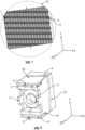
1 einen Ausschnitt einer Antenne mit mehreren Einzelstrahlern und einem Drehteller zur Rotation, -
2 einen Einzelstrahler in Draufsicht, -
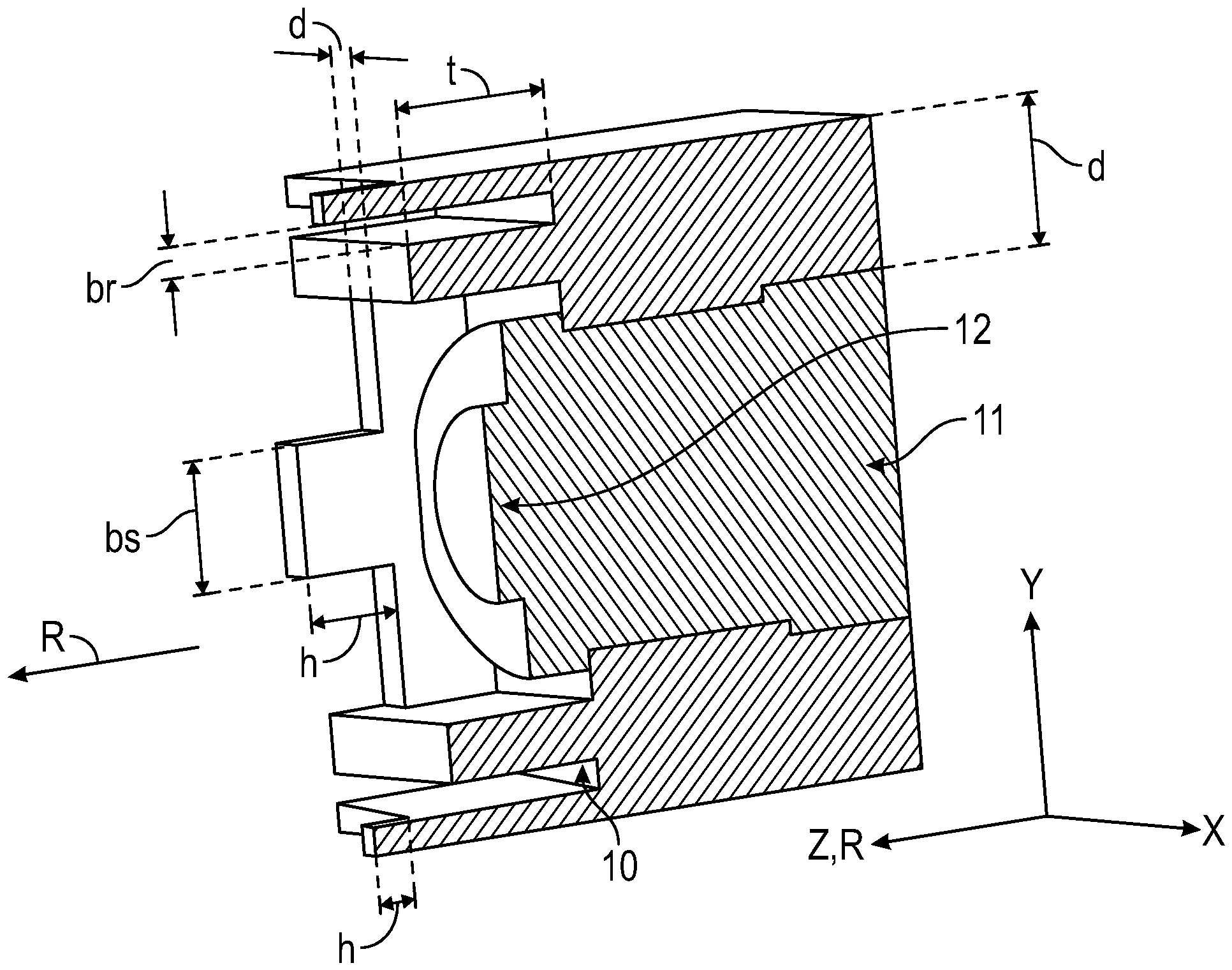
3 einen Einzelstrahler in Schnittdarstellung, und -
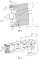
4 einen Einzelstrahler mit dahinterliegendem Phasenstellglied und Speisenetzwerk.
-
1 a section of an antenna with several individual radiators and a turntable for rotation, -
2 a single radiator in top view, -
3 a single radiator in cross-section, and -
4 a single radiator with a phase control element and feed network behind it.
Die Figuren sind lediglich schematische Darstellungen und dienen nur der Erläuterung der Erfindung. Gleiche oder gleichwirkende Elemente sind durchgängig mit den gleichen Bezugszeichen versehen.The figures are merely schematic representations and serve only to explain the invention. Identical or equivalent elements are provided with the same reference numerals throughout.
Eine Vielzahl von Einzelstrahlern 1, die in x- und y-Richtung benachbart zueinander in einem Antennenfeld angeordnet sind, bildet nach
Die Oberfläche der Antenne mit Ausrichtung in z-Richtung bildet eine Apertur der Antenne von der elektromagnetische Strahlung in Abstrahlungsrichtung R, die in z-Richtung oder einer Ablenkung von der z-Richtung von bis zu 70°, abgestrahlt wird. Wie später erläutert ist eine Auslenkung der Abstrahlungscharakteristik, insbesondere einer Hauptkeule, geplant, so dass tatsächlich die Abstrahlungsrichtung R sich von der z-Richtung um einen Scan-Winkel unterscheiden kann.The surface of the antenna aligned in the z-direction forms an aperture of the antenna from which electromagnetic radiation is emitted in the radiation direction R, which is emitted in the z-direction or a deflection from the z-direction of up to 70°. As explained later, a deflection of the radiation characteristic, in particular of a main lobe, is planned, so that the radiation direction R can actually differ from the z-direction by a scan angle.
Das Antennenfeld ist im Wesentlichen quadratisch, wobei in x-Richtung eine größere Anzahl von Einzelstrahlern 1 angeordnet ist als in y-Richtung. Dies ist dadurch ermöglicht, dass die Einzelstrahler 1 selbst nicht quadratisch sind, sondern in x-Richtung schmaler sind als in y-Richtung. Damit ist auch der Abstand zwischen den Einzelstrahlern 1 in x-Richtung geringer als in y-Richtung. In x-Richtung soll möglichst der Abstand dmax ![]()
![]()
Die Einzelstrahler 1 nach
Auf jeder der vier Trennwände 21, 22 ist eine Störstelle 3 in Form eines Pins angeordnet. Der Pin ragt in z-Richtung aus den Trennwänden 21, 22 heraus und ist jeweils mittig angeordnet. Damit ergibt sich über das Antennenfeld in periodische und symmetrische Anordnung der Störstellen 3.An
Inmitten der Trennwände 21, 22 entsteht ein Hohlraum, der von einem Dielektrikum 11, z.B. Teflon, mit einer Dielektrizitätskonstante ε > 1 zumindest teilweise gefüllt ist. Dieses Dielektrikum 11 schließt in etwa mit der Apertur ab und füllt vorteilhafterweise den gesamten Hohlraum aus, so dass sich auch kein Schmutz im Betrieb der Antenne festsetzen kann. Die Trennwände 21, 22 und die übrige Struktur der Einzelstrahler 1 bestehen aus einem Metall oder sind metallbeschichtet.A cavity is created in the middle of the
Entsprechend
Eine Breite br der Rille 10 beträgt etwa λ/10, eine Tiefe t der Rille 10 beträgt etwa ein Drittel der Breite br der Rille, also λ/30. Der Einzelstrahler 1 ist nicht als Hornstrahler mit einem Trichter, sondern als offenes Hohlleiterstück geformt, so dass sich der Hohlleiter nicht erweitert und über die Länge des Einzelstrahlers 1 einen ähnlichen Querschnitt aufweist. In z-Richtung ist auf dem Dielektrikum 11 ein Vorsprung 12 ausgeformt, der eine bestimmt Höhe und einen bestimmten Durchmesser ausweist, die sich entsprechend einer gewünschten optimalen Anpassung der Impedanz der Antenne an die Freiraumabstrahlung ergibt.A width br of the
Innerhalb des Speisenetzwerks 5 schließen sich an das Phasenstellglied 7 zwei Einkopplungen 9 an, die dazu dienen, für zwei getrennte zueinander orthogonale Polarisationen, beispielsweise eine horizontale Polarisation H und eine vertikale Polarisation V, getrennte Signale in den Hohlleiter einzuspeisen. Die Einkopplungen 9 sind vorzugsweise zueinander um 90° verdreht, also senkrecht zueinander im Hohlleiter angeordnet. Von den Einkopplungen 9 werden über Mikrostreifenleitungen und Hohleiter die Signale beider Polarisationen V, H an eine Sende-/Empfangseinrichtung 6 im Empfangsfall weitergeleitet bzw. im Sendefall werden die Signale beider Polarisationen V, H von der Sende-/Empfangseinrichtung 6 über die Einkopplungen 9 in den Hohlleiter und den Einzelstrahler 1 abgegeben.Within the feed network 5, two
Da der Einzelstrahler 1 nach
Weiterhin weist die Antenne eine Steuereinrichtung 8 auf, die sowohl mit dem Phasenstellglied 7 als auch der Sende-/Empfangseinrichtung 6 verbunden ist. Damit ist es der Steuereinrichtung 8 möglich, durch Einstellung unterschiedlicher Phasenlagen der Signale auf den benachbarten Einzelstrahlern 1, hier die in x-Richtung benachbarten Einzelstrahler 1, die Abstrahlungscharakteristik in x-Richtung auszulenken.The antenna also has a control device 8, which is connected to both the phase control element 7 and the transmitting/receiving device 6. This makes it possible for the control device 8 to deflect the radiation characteristics in the x-direction by setting different phase positions of the signals on the adjacent individual radiators 1, here the individual radiators 1 adjacent in the x-direction.
Dazu ist die Phasendifferenz benachbarter Einzelstrahler![]()
![]()
Eine Auslenkung in y-Richtung ist nicht vorgesehen. Im Zusammenwirken mit einer Drehung der Antennenapertur auf dem Drehteller 13 (und ggf. einem leichten Kippen der Antennenapertur) kann damit die Abstrahlungscharakteristik auf beliebige Winkel ausgerichtet werden. Bei einer auf einem Flugzeug montierten Antenne ist damit eine extrem kompakte Bauform ermöglicht, die durch fehlende großvolumige Kippelemente flach ist und auf ein voluminöses Radom verzichten kann. Gleichzeitig wurden durch die Gestaltung der Störstellen und der Lamellenstruktur 4 störende Resonanzen in der Aperturfläche vermieden, so dass sich eine hohe Effizienz und damit ein maximaler Antennengewinn auch über große Schwenkbereiche der Abstrahlungscharakteristik ergeben.A deflection in the y-direction is not provided. In conjunction with a rotation of the antenna aperture on the turntable 13 (and possibly a slight tilting of the antenna aperture), the radiation characteristics can be aligned to any angle. For an antenna mounted on an aircraft, this enables an extremely compact design that is flat due to the lack of large-volume tilting elements and does not require a voluminous radome. At the same time, the design of the defects and the lamella structure 4 avoids disruptive resonances in the aperture surface, resulting in high efficiency and thus maximum antenna gain even over large swivel ranges of the radiation characteristics.
Aufgrund des geringen Abstands zwischen den Einzelstrahlern 1 ist es schwierig, ein Speisenetzwerk 5 zu integrieren. Durch die größeren Abstände der Einzelstrahler 1 in y-Richtung und die durch die Lamellenstruktur 4 großflächigen Abstrahlung und kurzen offen Hohlleiterstücke statt Hornstrahlern war es möglich, in einem kleinen Bauraum das Speisenetzwerk 5 zu integrieren und trotzdem den Antennengewinn hoch zu halten.Due to the small distance between the individual radiators 1, it is difficult to integrate a feed network 5. Due to the larger distances between the individual radiators 1 in the y-direction and the large-area radiation provided by the lamellar structure 4 and short open waveguide sections instead of horn radiators, it was possible to integrate the feed network 5 in a small installation space and still keep the antenna gain high.
BEZUGSZEICHENLISTEREFERENCE SYMBOL LIST
- 11
- Einzelstrahlersingle radiator
- 22
- Trennwandpartition
- 33
- Störstellefault location
- 44
- Lamellenstrukturlamellar structure
- 55
- Speisenetzwerkfood network
- 66
- Sende-/Empfangseinrichtungtransmitting/receiving device
- 77
- Phasenstellgliedphase actuator
- 88
- Steuereinrichtungcontrol device
- 99
- Einkopplungcoupling
- 1010
- Rillegroove
- 1111
- Dielektrikumdielectric
- 1212
- Vorsprung im Dielektrikumadvance in dielectric
- 1313
- Drehteller turntable
- 21, 2221, 22
- Trennwände partition walls
- RR
- Abstrahlungsrichtungradiation direction
- DD
- Drehachseaxis of rotation
- H, VH, V
- Polarisationsrichtungenpolarization directions
- λλ
- Wellenlängewavelength
- bsbs
- Breite der Störstellewidth of the fault
- hh
- Höhe der Störstelleheight of the fault
- tt
- Tiefe der Rilledepth of the groove
- brbr
- Breite der Rillewidth of the groove
- dd
- Wandstärke der Trennwandwall thickness of the partition wall
Claims (14)
Priority Applications (4)
| Application Number | Priority Date | Filing Date | Title |
|---|---|---|---|
| DE102017112552.3A DE102017112552B4 (en) | 2017-06-07 | 2017-06-07 | ANTENNA WITH MULTIPLE INDIVIDUAL RADIATORS |
| PCT/DE2018/100419 WO2018224076A1 (en) | 2017-06-07 | 2018-05-03 | Antenna comprising a plurality of individual radiators |
| CN201880037230.1A CN110710053B (en) | 2017-06-07 | 2018-05-03 | Antenna with multiple individual radiators |
| US16/705,164 US11139586B2 (en) | 2017-06-07 | 2019-12-05 | Antenna comprising a plurality of individual radiators |
Applications Claiming Priority (1)
| Application Number | Priority Date | Filing Date | Title |
|---|---|---|---|
| DE102017112552.3A DE102017112552B4 (en) | 2017-06-07 | 2017-06-07 | ANTENNA WITH MULTIPLE INDIVIDUAL RADIATORS |
Publications (2)
| Publication Number | Publication Date |
|---|---|
| DE102017112552A1 DE102017112552A1 (en) | 2018-12-13 |
| DE102017112552B4 true DE102017112552B4 (en) | 2025-01-30 |
Family
ID=62245108
Family Applications (1)
| Application Number | Title | Priority Date | Filing Date |
|---|---|---|---|
| DE102017112552.3A Active DE102017112552B4 (en) | 2017-06-07 | 2017-06-07 | ANTENNA WITH MULTIPLE INDIVIDUAL RADIATORS |
Country Status (4)
| Country | Link |
|---|---|
| US (1) | US11139586B2 (en) |
| CN (1) | CN110710053B (en) |
| DE (1) | DE102017112552B4 (en) |
| WO (1) | WO2018224076A1 (en) |
Families Citing this family (3)
| Publication number | Priority date | Publication date | Assignee | Title |
|---|---|---|---|---|
| FR3144427A1 (en) * | 2022-12-22 | 2024-06-28 | Thales | Wide-angle impedance matching device for radiating element array antenna and method for designing such a device |
| DE102023124524A1 (en) * | 2023-09-12 | 2025-03-13 | Valeo Schalter Und Sensoren Gmbh | Waveguide antenna device for a radar system, transmitter-receiver device, radar system, driver assistance system, vehicle and method for operating a waveguide antenna device |
| DE102023129079A1 (en) * | 2023-10-23 | 2025-04-24 | Fraunhofer-Gesellschaft zur Förderung der angewandten Forschung eingetragener Verein | Horn antenna, antenna arrangement comprising a plurality of horn antennas, method for producing a horn antenna and method for producing an antenna arrangement |
Citations (8)
| Publication number | Priority date | Publication date | Assignee | Title |
|---|---|---|---|---|
| US6034647A (en) | 1998-01-13 | 2000-03-07 | Raytheon Company | Boxhorn array architecture using folded junctions |
| WO2014005699A1 (en) | 2012-07-03 | 2014-01-09 | Qest Quantenelektronische Systeme Gmbh | Antenna system for broadband satellite communication in the ghz frequency range, comprising a feeding arrangement |
| US20150048984A1 (en) | 2013-08-15 | 2015-02-19 | Tsinghua University | Waveguide horn arrays, methods for forming the same and antenna systems |
| DE102014112485A1 (en) | 2014-08-29 | 2016-03-03 | Lisa Dräxlmaier GmbH | HORN BEAM ANTENNA WITH REDUCED COUPLING BETWEEN ANTENNA ELEMENTS |
| DE102014112487A1 (en) | 2014-08-29 | 2016-03-03 | Lisa Dräxlmaier GmbH | GROUP ANTENNA OF HORN BEAMS WITH DIELECTRIC COVER |
| US20160072190A1 (en) | 2014-09-05 | 2016-03-10 | Lisa Draexlmaier Gmbh | Ridged horn antenna having additional corrugation |
| DE102015101721A1 (en) | 2015-02-06 | 2016-08-11 | Lisa Dräxlmaier GmbH | Positioning system for antennas |
| DE102016112583A1 (en) | 2016-07-08 | 2018-01-11 | Lisa Dräxlmaier GmbH | Controllable phase actuator for electromagnetic waves |
Family Cites Families (7)
| Publication number | Priority date | Publication date | Assignee | Title |
|---|---|---|---|---|
| US2438119A (en) * | 1942-11-03 | 1948-03-23 | Bell Telephone Labor Inc | Wave transmission |
| NL72696C (en) * | 1945-04-26 | |||
| NL1035877C (en) * | 2008-08-28 | 2010-03-11 | Thales Nederland Bv | An array antenna comprising means to suppress the coupling effect in the dielectric gaps between its radiator elements without establishing galvanic contacts. |
| CN103474777B (en) * | 2013-09-22 | 2015-07-22 | 浙江大学 | Loop traveling wave antenna generating radio frequency OAM on basis of metal ring cavity |
| US10454186B2 (en) * | 2015-02-24 | 2019-10-22 | Gilat Satellite Networks Ltd. | Lightweight plastic antenna |
| CN105261839B (en) * | 2015-11-03 | 2018-11-02 | 南京中网卫星通信股份有限公司 | A kind of C-Ku two-bands integration feed |
| CN109314314B (en) * | 2016-06-29 | 2021-08-27 | 胡贝尔和茹纳股份公司 | Array antenna |
-
2017
- 2017-06-07 DE DE102017112552.3A patent/DE102017112552B4/en active Active
-
2018
- 2018-05-03 WO PCT/DE2018/100419 patent/WO2018224076A1/en not_active Ceased
- 2018-05-03 CN CN201880037230.1A patent/CN110710053B/en active Active
-
2019
- 2019-12-05 US US16/705,164 patent/US11139586B2/en active Active
Patent Citations (8)
| Publication number | Priority date | Publication date | Assignee | Title |
|---|---|---|---|---|
| US6034647A (en) | 1998-01-13 | 2000-03-07 | Raytheon Company | Boxhorn array architecture using folded junctions |
| WO2014005699A1 (en) | 2012-07-03 | 2014-01-09 | Qest Quantenelektronische Systeme Gmbh | Antenna system for broadband satellite communication in the ghz frequency range, comprising a feeding arrangement |
| US20150048984A1 (en) | 2013-08-15 | 2015-02-19 | Tsinghua University | Waveguide horn arrays, methods for forming the same and antenna systems |
| DE102014112485A1 (en) | 2014-08-29 | 2016-03-03 | Lisa Dräxlmaier GmbH | HORN BEAM ANTENNA WITH REDUCED COUPLING BETWEEN ANTENNA ELEMENTS |
| DE102014112487A1 (en) | 2014-08-29 | 2016-03-03 | Lisa Dräxlmaier GmbH | GROUP ANTENNA OF HORN BEAMS WITH DIELECTRIC COVER |
| US20160072190A1 (en) | 2014-09-05 | 2016-03-10 | Lisa Draexlmaier Gmbh | Ridged horn antenna having additional corrugation |
| DE102015101721A1 (en) | 2015-02-06 | 2016-08-11 | Lisa Dräxlmaier GmbH | Positioning system for antennas |
| DE102016112583A1 (en) | 2016-07-08 | 2018-01-11 | Lisa Dräxlmaier GmbH | Controllable phase actuator for electromagnetic waves |
Also Published As
| Publication number | Publication date |
|---|---|
| US20200169003A1 (en) | 2020-05-28 |
| CN110710053A (en) | 2020-01-17 |
| US11139586B2 (en) | 2021-10-05 |
| WO2018224076A1 (en) | 2018-12-13 |
| DE102017112552A1 (en) | 2018-12-13 |
| CN110710053B (en) | 2022-01-25 |
Similar Documents
| Publication | Publication Date | Title |
|---|---|---|
| DE69613244T2 (en) | PLANAR GROUP ANTENNA FOR TWO FREQUENCIES | |
| DE69602052T2 (en) | Phase-controlled group antenna for multi-band operation with mutual use of radiators made of waveguides and tapered elements | |
| DE69725059T2 (en) | Broadband / double-band phase-controlled group antenna with stacked disc radiators on stacked dielectric cylinders | |
| EP3214695B1 (en) | Mobile radio antenna | |
| DE102017103161B4 (en) | Antenna device and antenna array | |
| DE102013205595B4 (en) | Mobile device and antenna arrangement therein | |
| DE60120174T2 (en) | Nested cross dipole antenna | |
| EP3411921B1 (en) | Dual-polarized antenna | |
| DE69901026T2 (en) | DOUBLE BAND ANTENNA | |
| EP0916169B1 (en) | Antenna system | |
| DE3855343T2 (en) | Phase controlled antenna system for two modes | |
| EP1344277B1 (en) | Antenna, in particular mobile radio antenna | |
| DE69621081T2 (en) | antenna arrays | |
| DE60302766T2 (en) | WAVEGUIDE | |
| DE102012103461B4 (en) | Circular polarization antenna | |
| DE69832592T2 (en) | DEVICE FOR RECEIVING AND SENDING RADIO SIGNALS | |
| EP1964205B1 (en) | Dual-polarized antenna having longitudinal or transverse webs | |
| DE102016112582A1 (en) | Phased array antenna element | |
| DE102011076209B4 (en) | antenna | |
| DE69910396T2 (en) | ANTENNA WITH AZIMUT AND ELEVATION BEAM SHAPING | |
| EP3533110B1 (en) | Dual-polarized horn radiator | |
| DE202022107107U1 (en) | Integrated base station antenna | |
| DE102017112552B4 (en) | ANTENNA WITH MULTIPLE INDIVIDUAL RADIATORS | |
| EP2375491B1 (en) | Leaky-wave antenna | |
| DE60019412T2 (en) | ANTENNA WITH VERTICAL POLARIZATION |
Legal Events
| Date | Code | Title | Description |
|---|---|---|---|
| R012 | Request for examination validly filed | ||
| R016 | Response to examination communication | ||
| R016 | Response to examination communication | ||
| R018 | Grant decision by examination section/examining division | ||
| R020 | Patent grant now final |