DE102017005299B3 - Adjusting device for adjusting at least one valve needle of an injection molding apparatus - Google Patents
Adjusting device for adjusting at least one valve needle of an injection molding apparatus Download PDFInfo
- Publication number
- DE102017005299B3 DE102017005299B3 DE102017005299.9A DE102017005299A DE102017005299B3 DE 102017005299 B3 DE102017005299 B3 DE 102017005299B3 DE 102017005299 A DE102017005299 A DE 102017005299A DE 102017005299 B3 DE102017005299 B3 DE 102017005299B3
- Authority
- DE
- Germany
- Prior art keywords
- guide
- push rod
- guide surfaces
- sliding
- hot runner
- Prior art date
- Legal status (The legal status is an assumption and is not a legal conclusion. Google has not performed a legal analysis and makes no representation as to the accuracy of the status listed.)
- Active
Links
Images

Classifications
-
- B—PERFORMING OPERATIONS; TRANSPORTING
- B29—WORKING OF PLASTICS; WORKING OF SUBSTANCES IN A PLASTIC STATE IN GENERAL
- B29C—SHAPING OR JOINING OF PLASTICS; SHAPING OF MATERIAL IN A PLASTIC STATE, NOT OTHERWISE PROVIDED FOR; AFTER-TREATMENT OF THE SHAPED PRODUCTS, e.g. REPAIRING
- B29C45/00—Injection moulding, i.e. forcing the required volume of moulding material through a nozzle into a closed mould; Apparatus therefor
- B29C45/17—Component parts, details or accessories; Auxiliary operations
- B29C45/26—Moulds
- B29C45/27—Sprue channels ; Runner channels or runner nozzles
- B29C45/28—Closure devices therefor
- B29C45/2806—Closure devices therefor consisting of needle valve systems
- B29C45/281—Drive means therefor
-
- B—PERFORMING OPERATIONS; TRANSPORTING
- B29—WORKING OF PLASTICS; WORKING OF SUBSTANCES IN A PLASTIC STATE IN GENERAL
- B29C—SHAPING OR JOINING OF PLASTICS; SHAPING OF MATERIAL IN A PLASTIC STATE, NOT OTHERWISE PROVIDED FOR; AFTER-TREATMENT OF THE SHAPED PRODUCTS, e.g. REPAIRING
- B29C45/00—Injection moulding, i.e. forcing the required volume of moulding material through a nozzle into a closed mould; Apparatus therefor
- B29C45/17—Component parts, details or accessories; Auxiliary operations
- B29C45/26—Moulds
- B29C45/27—Sprue channels ; Runner channels or runner nozzles
- B29C45/28—Closure devices therefor
- B29C45/2806—Closure devices therefor consisting of needle valve systems
- B29C45/281—Drive means therefor
- B29C2045/2813—Common drive means for several needle valves
-
- B—PERFORMING OPERATIONS; TRANSPORTING
- B29—WORKING OF PLASTICS; WORKING OF SUBSTANCES IN A PLASTIC STATE IN GENERAL
- B29C—SHAPING OR JOINING OF PLASTICS; SHAPING OF MATERIAL IN A PLASTIC STATE, NOT OTHERWISE PROVIDED FOR; AFTER-TREATMENT OF THE SHAPED PRODUCTS, e.g. REPAIRING
- B29C45/00—Injection moulding, i.e. forcing the required volume of moulding material through a nozzle into a closed mould; Apparatus therefor
- B29C45/17—Component parts, details or accessories; Auxiliary operations
- B29C45/26—Moulds
- B29C45/27—Sprue channels ; Runner channels or runner nozzles
- B29C45/28—Closure devices therefor
- B29C45/2806—Closure devices therefor consisting of needle valve systems
- B29C45/281—Drive means therefor
- B29C2045/2824—Needle valves driven by an electric motor
Landscapes
- Engineering & Computer Science (AREA)
- Manufacturing & Machinery (AREA)
- Mechanical Engineering (AREA)
- Moulds For Moulding Plastics Or The Like (AREA)
Abstract
Stelleinrichtung zum Verstellen wenigstens einer Ventilnadel einer Spritzgießvorrichtung mit einem Heißkanalverteiler (11), an dem wenigstens eine Heißkanaldüse (12) angeordnet ist, durch die sich wenigstens eine Ventilnadel (14) erstreckt, mittels welcher die Strömung einer Schmelze durch die Heißkanaldüse (12) steuerbar ist. Die Stellvorrichtung weist eine mit der wenigstens einen Ventilnadel (14) verbundene Trägerplatte (21) auf, welche gegenüber dem Heißkanalverteiler (11) in einer ersten, zur Betätigungsrichtung der Ventilnadeln (14) parallelen Richtung (1) hin- und her verschiebbar ist. Ferner weist die Stelleinrichtung eine Hubeinrichtung (25) zum Verschieben der Trägerplatte (21) in der ersten Richtung (1) gegenüber dem Heißkanalverteiler (11) auf, wobei die Hubeinrichtung (25) einen Schiebemechanismus (40) und einen mit einer Ansteuereinrichtung (27) verbundenen Stellantrieb (28) zum Erzeugen einer Linearbewegung aufweist, wobei der Schiebemechanismus (40) wenigstens eine Schubstange (41, 42) und aufweist, die in einer gegenüber der ersten Richtung (1) angewinkelten zweiten Richtung (2) hin- und her verschiebbar gelagert ist.Adjusting device for adjusting at least one valve needle of an injection molding apparatus with a hot runner manifold (11), on which at least one hot runner nozzle (12) is arranged, through which at least one valve needle (14) extends, by means of which the flow of a melt through the hot runner nozzle (12) controllable is. The adjusting device has a support plate (21) which is connected to the at least one valve needle (14) and which is displaceable relative to the hot runner manifold (11) in a first direction (1) parallel to the actuation direction of the valve needles (14). Furthermore, the adjusting device has a lifting device (25) for displacing the carrier plate (21) in the first direction (1) with respect to the hot runner distributor (11), wherein the lifting device (25) has a sliding mechanism (40) and one with a drive device (27). connected actuator (28) for generating a linear movement, wherein the sliding mechanism (40) at least one push rod (41, 42) and which, in a relative to the first direction (1) angled second direction (2) back and forth mounted is.
Description
Die Erfindung betrifft eine Stelleinrichtung zum Verstellen wenigstens einer Ventilnadel einer Spritzgießvorrichtung mit einem Heißkanalverteiler, an dem wenigstens eine Heißkanaldüse angeordnet ist, durch die sich wenigstens eine Ventilnadel erstreckt, mittels welcher die Strömung einer Schmelze durch die Heißkanaldüse steuerbar ist.The invention relates to an adjusting device for adjusting at least one valve needle of an injection molding apparatus with a hot runner manifold, on which at least one hot runner nozzle is arranged, through which extends at least one valve needle, by means of which the flow of a melt through the hot runner nozzle is controllable.
Derartige Stelleinrichtungen sind bekannt, beispielsweise beschreibt die internationale Patentanmeldung
Eine weniger komplexe und kompaktere Lösung wird im europäischen Patent
Eine ebenfalls weniger komplexe kompaktere Lösung ist aus dem europäischen Patent
Aus der US-Patentanmeldung
Eine weitere Herausforderung bei der Betätigung einer mit den Ventilnadeln fest verbundenen Trägerplatte sind hierfür erforderlichen hohen Kräfte in axialer Richtung der Ventilnadeln. Diese führen bei der Betätigung der Trägerplatte mittels der Stelleinrichtung insbesondere bei einer ungleichen Kraftverteilung zur Ausbildung von Drehmomenten auf die Trägerplatte. Damit einhergehende Verwindungen bzw. Durchbiegungen der Trägerplatte führen zu einem Präzisionsverlust bezüglich der gewünschten parallelen Betätigung der Ventilnadeln.Another challenge in the operation of a firmly connected with the valve pins carrier plate are required for this high forces in the axial direction of the valve needles. These result in the actuation of the support plate by means of the adjusting device, in particular with an uneven force distribution for the formation of torques on the support plate. Associated torsions or deflections of the carrier plate lead to a loss of precision with respect to the desired parallel operation of the valve pins.
Die Erfindung stellt sich daher die Aufgabe, eine Stelleinrichtung zum Verstellen wenigstens einer Ventilnadel einer Spritzgießvorrichtung zur Verfügung zu stellen, welche die oben genannten Nachteile verbessert.The invention therefore has the object to provide an adjusting device for adjusting at least one valve needle of an injection molding device, which improves the above-mentioned disadvantages.
Dies wird erfindungsgemäß durch eine Stelleinrichtung gemäß der Lehre des Anspruchs 1 erreicht. Zu bevorzugende Weiterbildungen der Erfindung sind Gegenstand der Unteransprüche.This is inventively achieved by an adjusting device according to the teaching of claim 1. Preferred developments of the invention are the subject of the dependent claims.
Zur Lösung der Aufgabe wird eine Stelleinrichtung zum Verstellen wenigstens einer Ventilnadel einer Spritzgießvorrichtung vorgeschlagen. Die Spritzgießvorrichtung weist einen Heißkanalverteiler auf, an dem wenigstens eine Heißkanaldüse angeordnet ist, durch die sich wenigstens eine Ventilnadel erstreckt, mittels welcher die Strömung einer Schmelze durch die Heißkanaldüse steuerbar ist.To solve the problem, an adjusting device for adjusting at least one valve needle of an injection molding device is proposed. The injection molding apparatus has a hot runner manifold on which at least one hot runner nozzle is arranged, through which extends at least one valve needle, by means of which the flow of a melt through the hot runner nozzle can be controlled.
Die Stelleinrichtung weist eine mit der wenigstens einen Ventilnadel verbundene Trägerplatte auf, welche gegenüber dem Heißkanalverteiler in einer ersten, zur Betätigungsrichtung der Ventilnadeln parallelen Richtung hin- und her verschiebbar ist. Ferner weist die Stelleinrichtung eine Hubeinrichtung zum Verschieben der Trägerplatte in der ersten Richtung gegenüber dem Heißkanalverteiler auf, wobei die Hubeinrichtung einen Schiebemechanismus und einen mit einer Ansteuereinrichtung verbundenen Stellantrieb zum Erzeugen einer Linearbewegung aufweist. The adjusting device has a carrier plate which is connected to the at least one valve needle and which can be displaced back and forth relative to the hot runner distributor in a direction parallel to the actuating direction of the valve needles. Furthermore, the adjusting device has a lifting device for displacing the carrier plate in the first direction relative to the hot runner manifold, wherein the lifting device has a sliding mechanism and an actuator connected to a drive device for generating a linear movement.
Der Schiebemechanismus weist wenigstens eine Schubstange auf, die insbesondere beabstandet zur Trägerplatte angeordnet ist. Die Schubstange ist in einer gegenüber der ersten Richtung angewinkelten zweiten Richtung hin- und her verschiebbar gelagert.The sliding mechanism has at least one push rod, which is arranged in particular spaced from the carrier plate. The push rod is slidably mounted back and forth in a second direction angled relative to the first direction.
Erfindungsgemäß weist die wenigstens eine Schubstange wenigstens ein Schubelement auf, das eine in einer gegenüber der zweiten Richtung angewinkelt angeordnete Schubelementführung aufweist, wobei die Schubelementführung wenigstens zwei geneigte Führungsflächen aufweist. An der Trägerplatte ist im Bereich jedes Schubelements ein erstes Schiebeelement mit einer ersten Schiebelementführung angeordnet, welche entsprechend der Schubelementführung gegenüber der zweiten Richtung angewinkelt angeordnet ist, und wenigstens zwei entsprechend der Führungsflächen der Schubelementführung geneigte Führungsflächen aufweist. Das Schubelement und das erste Schiebeelement sind entlang der jeweiligen Führungsflächen gegeneinander verschiebbar. Dabei ist die Neigung der Führungsflächen so ausgebildet, dass über die jeweilige Führung sowohl in der ersten Richtung und in einer quer zur ersten Richtung und zur zweiten Richtung angeordneten dritten Richtung wirkende Kräfte als auch auf die Trägerplatte wirkende Drehmomente übertragbar sind. Bei dieser Gestaltung wirkt jeweils ein Schubelement so mit einem ersten Schiebeelement zusammen, dass eine Bewegung der Schubstange in der zweiten Richtung eine Bewegung der Trägerplatte in der ersten Richtung bewirkt.According to the invention, the at least one push rod has at least one push element which has a push element guide arranged in an angle with respect to the second direction, the push element guide having at least two inclined guide surfaces. On the carrier plate in the region of each thrust element, a first sliding element is arranged with a first sliding element guide, which is arranged according to the Schubelementführung angled relative to the second direction, and at least two corresponding to the guide surfaces of the Schubelementführung inclined guide surfaces. The thrust element and the first sliding element are displaceable against each other along the respective guide surfaces. In this case, the inclination of the guide surfaces is formed so that acting on the respective guide both in the first direction and in a transversely to the first direction and the second direction arranged third direction acting forces and acting on the support plate torques are transferable. In this configuration, a pusher member cooperates with a first pusher member such that movement of the pusher rod in the second direction causes movement of the carrier plate in the first direction.
Die dritte Richtung ist quer zur ersten und zur zweiten Richtung angeordnet, wobei diese insbesondere im Wesentlichen orthogonalen zur ersten und zur zweiten Richtung angeordnet ist. Die Betätigungsrichtung der Ventilnadeln stimmt dabei nicht bei jeder möglichen Ausführungsform mit der Axialrichtung der Ventilnadeln überein, da mit der vorgeschlagenen Stelleinrichtungen auch Ventilnadeln von Heißkanaldüsen betätigbar sind, deren wenigstens eine Ventilnadel angewinkelt zu deren Betätigungsrichtung angeordnet ist, wie beispielsweise bei Heißkanaldüsen zum seitlichen Angießen.The third direction is arranged transversely to the first and to the second direction, wherein this is arranged in particular substantially orthogonal to the first and to the second direction. The actuating direction of the valve needles is not the same in every possible embodiment with the axial direction of the valve needles, as with the proposed actuators and valve needles of hot runner nozzles are actuated, at least one valve needle is angled to its operating direction is arranged, such as hot runner nozzles for lateral casting.
Die Hubeinrichtung weist neben dem Schiebemechanismus auch einen mit einer Ansteuereinrichtung verbundenen Stellantrieb zum Erzeugen einer Linearbewegung auf. Der Stellantrieb kann dabei jedes geeignete Antriebskonzept aufweisen, wie beispielsweise einen Elektroantrieb in Form eines Servomotors. Je nach Umfeld und Einsatzzweck kann der Stellantrieb auch als hydraulisch oder pneumatisch angetriebener Antriebsmotor ausgeführt sein. Der Stellantrieb ist mit einer Ansteuereinrichtung verbunden, welche beispielsweise mit der Maschinensteuerung verbunden oder in diese integriert sein kann, um die im Spritzgießverfahren der Spritzgießmaschine erforderlichen Ventilöffnungszeiten und damit die Strömung der Schmelze durch die Heißkanaldüse zu steuern.The lifting device has in addition to the sliding mechanism also connected to a drive actuator for generating a linear movement. The actuator can have any suitable drive concept, such as an electric drive in the form of a servo motor. Depending on the environment and intended use, the actuator can also be designed as a hydraulically or pneumatically driven drive motor. The actuator is connected to a drive device, which may be connected, for example, to the machine control or integrated into it, in order to control the valve opening times required in the injection molding of the injection molding machine and thus the flow of the melt through the hot runner nozzle.
Jede Schubstange weist wenigstens ein Schubelement auf, welches einstückig mit der Schubstange ausgebildet sein kann, oder auch mit der Schubstange verbunden ausgebildet sein kann.Each push rod has at least one push element, which may be formed integrally with the push rod, or may be formed connected to the push rod.
Die hier vorgeschlagene Führung weist wenigstens zwei geneigte Führungsflächen auf. Bei der Führung handelt es sich insbesondere um eine linear verlaufende Führung, deren Führungsflächen gegenüber der Längsrichtung der Führung geneigt ausgebildet ist, so dass die Führungsflächen in einer Art „Dachprofil“ miteinander einen Neigungswinkel einschließen. Auf diese Weise ist ein Schiebeelement in Längsrichtung der Führungsflächen von Schiebelement und Schubelement bewegbar am Schubelement gelagert. Kräfte bzw. deren Kraftkomponenten und Drehmomente, die in einer von der Längsrichtung (zweite Richtung) abweichenden Richtung wirken, werden wenigstens teilweise über die geneigten Führungsflächen aufgenommen und zwar sowohl in der ersten Richtung und damit parallel zur Betätigungsrichtung der Ventilnadeln als auch in einer quer hierzu angeordneten Richtung, welche eher seitlich auf die Trägerplatte wirken.The guide proposed here has at least two inclined guide surfaces. The guide is, in particular, a linearly extending guide, whose guide surfaces are inclined relative to the longitudinal direction of the guide, so that the guide surfaces enclose an angle of inclination with each other in a kind of "roof profile". In this way, a sliding element in the longitudinal direction of the guide surfaces of sliding element and thrust element is movably mounted on the thrust element. Forces or their force components and torques, which act in a direction deviating from the longitudinal direction (second direction), are accommodated at least partially over the inclined guide surfaces both in the first direction and thus parallel to the actuation direction of the valve needles and in a transverse direction thereto arranged direction, which act laterally on the support plate.
Die Neigung der Führungsflächen ist so ausgebildet, dass über die jeweilige Führung Kräfte und Drehmomente aufgenommen werden können, welche in sowohl der ersten Richtung als auch in einer zur ersten Richtung und zur zweiten Richtung im Wesentlichen orthogonalen bzw. quer hierzu angeordneten dritten Richtung wirken. Da die zweite Richtung auch in einem von 90° abweichenden Winkel gegenüber der ersten Richtung angewinkelt sein kann, sind auch Ausführungsformen möglich, bei welchen die dritte Richtung im Wesentlichen orthogonal zur ersten und zweiten Richtung angeordnet ist, jedoch die erste und zweite Richtung nicht im Wesentlichen orthogonal zueinander angeordnet sind.The inclination of the guide surfaces is designed such that forces and torques can be picked up via the respective guide, which act in both the first direction and in a third direction substantially orthogonal to the first direction and to the second direction. Since the second direction may also be angled at an angle deviating from 90 ° with respect to the first direction, embodiments are also possible in which the third direction is arranged substantially orthogonal to the first and second directions, but the first and second directions are not substantially are arranged orthogonal to each other.
Auf diese Weise trägt der vorgeschlagene Schiebemechanismus zur Stabilisierung der Trägerplatte und zu einer präzisen Ventilnadelbewegung bei. Dies ist insbesondere vorteilhaft bezüglich auf die Trägerplatte wirkender Momente, welche zu einer Auslenkung bzw. Verwindung oder Wölbung der Trägerplatte führen können und damit die Präzision der parallelen Betätigung aller an der Trägerplatte angeordneten Ventilnadeln und damit die parallele Füllung der Spritzgießkavitäten beeinträchtigen. So können in der dritten Richtung wirkende Kräfte durch die bei Spritzgießvorrichtungen üblicherweise vorgesehenen Säulenführungen relativ gut aufgenommen werden, ohne die Präzision der Trägerplattenbetätigung zu beeinträchtigen. Kräfte bzw. Drehmomente, die insbesondere in einer zur dritten Richtung angewinkelten Richtung wirken und damit eine unsymmetrische Trägerplattenbewegung bzw. Plattenverwindung begünstigen können, werden von bekannten Führungskonzepten nur zum Teil aufgenommen. Die vorgeschlagene Lösung ermöglicht die Aufnahme solcher Kräfte bzw. Drehmomente durch den Schiebemechanismus und ermöglicht so eine gleichmäßigere und präzisere Verstellbewegung der Trägerplatte. Aufgrund der gegenüber bekannten Stelleinrichtungen verbesserten Aufnahme von Kräften und Momenten über die geneigten Führungsflächen wird auch eine Gestaltung mit nur einer einzigen bzw. einzelnen Schubstange ermöglicht.In this way, the proposed sliding mechanism contributes to the stabilization of the carrier plate and to a precise valve needle movement at. This is particularly advantageous with respect to acting on the support plate moments, which can lead to a deflection or twisting or curvature of the support plate and thus affect the precision of the parallel operation of all arranged on the support plate valve needles and thus the parallel filling of the injection molding cavities. Thus, forces acting in the third direction can be absorbed relatively well by the column guides usually provided in injection molding apparatuses without impairing the precision of the support plate actuation. Forces or torques that act in particular in a direction that is angled toward the third direction and thus can promote asymmetrical carrier plate movement or plate twisting are only partially absorbed by known guidance concepts. The proposed solution enables the absorption of such forces or torques by the sliding mechanism and thus allows a more uniform and precise adjustment of the support plate. Due to the comparison with known adjusting devices improved absorption of forces and moments on the inclined guide surfaces and a design with only a single or single push rod is possible.
Im Zusammenhang mit der vorliegenden Erfindung ist angegeben, dass an der Trägerplatte im Bereich jedes Schubelements ein erstes Schiebeelement angeordnet ist. Selbstverständlich können auch zwei Schiebeelemente im Bereich eines Schubelements angeordnet sein, ohne vom Erfindungsgedanken abzuweichen. Die Zahl und Anordnung von Schub- und Schiebeelementen hängt dabei unter anderem insbesondere von der Gestaltung der Spritzgießvorrichtung, der Formwerkzeuge und der beim Spritzgießprozess auftretenden Betätigungskräfte der Ventilnadeln ab.In connection with the present invention, it is stated that a first sliding element is arranged on the carrier plate in the region of each push element. Of course, two sliding elements can be arranged in the region of a thrust element, without departing from the inventive idea. The number and arrangement of push and slide elements depends inter alia, in particular, on the design of the injection molding device, the molds and the actuating forces of the valve needles occurring during the injection molding process.
Bei einer Ausführungsform der Stelleinrichtung weist der Schiebemechanismus wenigstens eine an jeder der wenigstens einen Schubstange angeordnete Schubstangenführung auf, welche zum Führen der Schubstange in der zweiten Richtung dient. Die Schubstangenführung ist dabei insbesondere vorteilhaft an einer den Schubelementen gegenüberliegenden Seite der Schubstange angeordnet. Insbesondere weist dabei auch die Schubstangenführung wenigstens zwei zueinander geneigte Führungsflächen auf, mittels welcher sowohl in der ersten und zweiten Richtung und in einer quer dazu angeordneten dritten Richtung wirkende Kräfte bzw. Kraftkomponenten als auch auf die Trägerplatte wirkende Drehmomente übertragbar sind. Dabei kann diese Führung vorteilhaft auch entsprechend der Führung an den Schubelementen ausgeführt sein.In one embodiment of the adjusting device, the sliding mechanism has at least one push rod guide arranged on each of the at least one push rod, which serves to guide the push rod in the second direction. The push rod guide is particularly advantageously arranged on a side opposite the push elements side of the push rod. In particular, the push rod guide also has at least two mutually inclined guide surfaces, by means of which acting in the first and second directions and in a third direction transverse thereto acting forces or force components as well as acting on the support plate torques are transferable. In this case, this guide can be advantageously carried out according to the guide on the pushers.
Bei einer Ausführungsform der Stelleinrichtung weist der Schiebemechanismus jeweils wenigstens ein gegenüber der an der wenigstens einen Schubstange angeordneten Schubstangenführung angeordnetes zweites Schiebeelement auf, das eine in der zweiten Richtung angeordnete zweite Schiebelementführung mit wenigstens zwei entsprechend den Führungsflächen der Schubstangenführung geneigten Führungsflächen aufweist. Die Schubstange und das zweite Schiebeelement sind dabei entlang der jeweiligen Führungsflächen gegeneinander verschiebbar, so dass über die Führungsflächen sowohl in der ersten Richtung und in der dritten Richtung wirkende Kräfte bzw. Kraftkomponenten als auch auf die Trägerplatte wirkende Drehmomente aufnehmbar sind. Das wenigstens eine gegenüber der wenigstens einen Schubstange angeordnete zweite Schiebeelement ist dabei insbesondere stationär an der Spritzgießvorrichtung angeordnet und die Schubstange dadurch in Richtung der Führungsflächen jeweils beweglich gegenüber der Spritzgießvorrichtung gelagert. Über die geneigten Führungsflächen an Schubstange und zweitem Schiebeelement sind damit an der Trägerplatte wirkende Kräfte bzw. Drehmomente von der Spritzgießvorrichtung aufnehmbar.In one embodiment of the adjusting device, the sliding mechanism has at least one second sliding element arranged opposite the sliding rod guide arranged on the at least one push rod and having a second sliding element guide arranged in the second direction with at least two guide surfaces inclined corresponding to the guide surfaces of the sliding rod guide. The push rod and the second sliding element are displaceable relative to one another along the respective guide surfaces, so that forces acting on the guide surfaces in both the first direction and in the third direction or force components and torques acting on the carrier plate can be accommodated. The at least one arranged opposite the at least one push rod second sliding element is arranged in particular stationary on the injection molding and the push rod thereby in each case in the direction of the guide surfaces movably mounted relative to the injection molding. About the inclined guide surfaces of push rod and second sliding element acting on the support plate forces or torques are received by the injection molding.
Bei einer Ausführungsform der Stelleinrichtung sind die wenigstens zwei zueinander geneigten Führungsflächen im Wesentlichen orthogonal zueinander angeordnet. Bei etwa senkrecht zueinander angeordneten Führungsflächen kann eine besonders günstige Kraftverteilung in der Führung erreicht werden. Allerdings kann bei Kräften, die in einer bekannten Vorzugsrichtung wirken, die Neigung der Führungsflächen auch der vorliegenden Anforderung entsprechend anderweitig günstig ausgelegt werden, wobei in einem solchen Fall auch eine andere Anordnung der zueinander geneigten Führungsflächen mit einem anderen als im Wesentlichen orthogonalen Winkel günstig sein kann.In one embodiment of the adjusting device, the at least two mutually inclined guide surfaces are arranged substantially orthogonal to one another. In approximately perpendicularly arranged guide surfaces, a particularly favorable force distribution in the guide can be achieved. However, with forces acting in a known preferred direction, the inclination of the guide surfaces can also be designed to be favorable in accordance with the present requirement, in which case another arrangement of the mutually inclined guide surfaces with an angle other than substantially orthogonal may be favorable ,
Bei einer Ausführungsform der Stelleinrichtung weisen die Schubelementführung und die erste Schiebeelementführung und/ oder die Schubstangenführung und die zweite Schiebeelementführung jeweils vier Führungsflächen auf, wobei wenigstens jeweils zwei Führungsflächen zueinander geneigt angeordnet sind. Bei einer solchen Ausführungsform einer Stelleinrichtung sind auf bzw. an der Trägerplatte und Ventilnadeln wirkende Kräfte und Drehmomente besonders zuverlässig aufnehmbar und ein die Präzision der Ventilnadelbewegung verringerndes Spiel reduzierbar.In one embodiment of the adjusting device, the thrust element guide and the first sliding element guide and / or the push rod guide and the second sliding element guide each have four guide surfaces, wherein at least two guide surfaces are arranged inclined to each other. In such an embodiment of an actuating device forces and torques acting on or on the carrier plate and valve needles can be received particularly reliably and a clearance reducing the precision of the valve needle movement can be reduced.
Bei einer Ausführungsform der Stelleinrichtung weist der Schiebemechanismus wenigstens zwei miteinander verbundene Schubstangen auf, die parallel zueinander und insbesondere beabstandet zur Trägerplatte angeordnet sind. Die wenigstens zwei miteinander verbundenen Schubstangen sind dabei in einer gegenüber der ersten Richtung angewinkelten zweiten Richtung hin- und her verschiebbar gelagert.In one embodiment of the adjusting device, the sliding mechanism has at least two interconnected push rods, which are arranged parallel to one another and in particular spaced from the carrier plate. The at least two interconnected push rods are in a relation to the first direction Angled second direction back and forth slidably mounted.
Bei einer Ausführungsform der Stelleinrichtung sind zwischen den zueinander geneigten Führungsflächen der Schubelementführung und der ersten Schiebeelementführung und/ oder zwischen den zueinander geneigten Führungsflächen der Schubstangenführung und der zweiten Schiebeelementführung jeweils Wälzkörper angeordnet. Durch die Anordnung von Wälzkörpern zwischen den Führungsflächen wird die Gefahr von Haftreibungseffekten minimiert und die Reibung verringert, sodass eine verbesserte Verstellung der Ventilnadeln mit verringerten Stellkräften möglich ist. Durch die Verringerung der Reibung verringert sich auch die Verschleißfestigkeit, wodurch sich aufgrund höherer Bewegungsgeschwindigkeiten auch schnellere Verschlusszeiten verwirklichen lassen.In one embodiment, the adjusting device between the mutually inclined guide surfaces of the thrust element guide and the first slide element guide and / or between the mutually inclined guide surfaces of the push rod guide and the second slide element guide each rolling elements are arranged. The arrangement of rolling elements between the guide surfaces, the risk of static friction effects is minimized and reduced friction, so that an improved adjustment of the valve pins with reduced actuating forces is possible. Reducing friction also reduces wear resistance, resulting in faster shutter speeds due to faster movement speeds.
Bei einer Ausführungsform der Stelleinrichtung mit Wälzkörpern sind diese in einer im Schubelement und/ oder im ersten Schiebeelement angeordneten Nut umlaufend angeordnet. Gleichzeitig oder wahlweise können die Wälzkörper auch in einer im Schubelement und/ oder im zweiten Schiebeelement angeordneten Nut umlaufend angeordnet sein. Eine umlaufende Anordnung von Wälzkörpern bietet den zusätzlichen Vorteil, dass kein die Präzision verringerndes Spiel zwischen der Nut und den Wälzkörpern vorgesehen sein muss. Wahlweise kann vorgesehen sein, dass sich die Wälzkörper frei in der Nut bewegen oder in einem Käfig geführt werden.In one embodiment of the adjusting device with rolling elements, these are circumferentially arranged in a groove arranged in the thrust element and / or in the first sliding element. At the same time or alternatively, the rolling elements can also be arranged circumferentially in a groove arranged in the pushing element and / or in the second sliding element. A circumferential arrangement of rolling elements offers the additional advantage that no precision-reducing clearance between the groove and the rolling elements must be provided. Optionally, it can be provided that the rolling elements move freely in the groove or are guided in a cage.
Weitere Merkmale, Vorteile und Anwendungsmöglichkeiten der Erfindung ergeben sich aus der nachfolgenden Beschreibung im Zusammenhang mit den Figuren. Es zeigt:
-
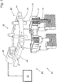
1 eine teilweise Schnittansicht eines Teils einer Spritzgießvorrichtung mit einer beispielhaften schematisch dargestellten Stelleinrichtung, wobei nicht jedes erfindungsgemäße Merkmal der Stelleinrichtung dargestellt ist; -
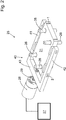
2 die beispielhafte Ausführungsform der in1 schematisch dargestellten Hubeinrichtung zum Verschieben der Trägerplatte in einer weiteren Darstellung in welcher nicht jedes erfindungsgemäße Merkmal der Stelleinrichtung gezeigt ist; -
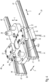
3 eine Schnittdarstellung durch die beispielhafte Stelleinrichtung aus1 , in welcher nicht jedes erfindungsgemäße Merkmal der Stelleinrichtung gezeigt ist; -
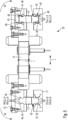
4 eine detailliertere dreidimensionale Darstellung einer weiteren beispielhaften erfindungsgemäßen Stelleinrichtung; und -
5 eine teilweise Schnittansicht einer beispielhaften erfindungsgemäßen Stelleinrichtung aus4 .
-
1 a partial sectional view of a portion of an injection molding apparatus with an exemplary schematically illustrated adjusting device, not all inventive feature of the adjusting device is shown; -
2 the exemplary embodiment of in1 schematically shown lifting device for moving the support plate in a further illustration in which not every inventive feature of the actuator is shown; -
3 a sectional view through the exemplary adjusting device1 in which not every feature of the actuator according to the invention is shown; -
4 a more detailed three-dimensional representation of another exemplary adjusting device according to the invention; and -
5 a partial sectional view of an exemplary adjusting device according to the invention from4 ,
In
Bei der in
Der beispielhafte Schiebemechanismus
Zum Bewegen der Trägerplatte
Das Stellelement
Wie in
Bei der in
In
BezugszeichenlisteLIST OF REFERENCE NUMBERS
- 11
- erste Richtungfirst direction
- 22
- zweite Richtungsecond direction
- 33
- dritte Richtungthird direction
- 1010
- Spritzgießvorrichtunginjection molding
- 1111
- HeißkanalverteilerManifold
- 1212
- Heißkanaldüsehot runner nozzle
- 1414
- Ventilnadelvalve needle
- 1717
- stationäre Formplattestationary mold plate
- 2020
- Stelleinrichtungsetting device
- 2121
- Trägerplattesupport plate
- 2222
- Halteelementretaining element
- 2525
- Hubeinrichtunglifting device
- 2626
- Säulenführungcolumn guide
- 2727
- Ansteuereinrichtungdriving
- 2828
- Stellantriebactuator
- 2929
- Stellelementactuator
- 4040
- Schiebemechanismussliding mechanism
- 4141
- erste Schubstangefirst push rod
- 4242
- zweite Schubstangesecond push rod
- 4343
- Querstangecrossbar
- 4444
- SchubelementführungPushing member guide
- 44a44a
- geneigte Führungsflächeinclined guide surface
- 44b44b
- geneigte Führungsflächeinclined guide surface
- 44c44c
- geneigte Führungsflächeinclined guide surface
- 44d44d
- geneigte Führungsflächeinclined guide surface
- 4545
- erstes Schiebelementfirst sliding element
- 4646
- erste Schiebeelementführungfirst sliding element guide
- 46a46a
- geneigte Führungsflächeinclined guide surface
- 46b46b
- geneigte Führungsflächeinclined guide surface
- 46c46c
- geneigte Führungsflächeinclined guide surface
- 46d46d
- geneigte Führungsflächeinclined guide surface
- 4747
- Schubelementpush element
- 4848
- Wälzkörperrolling elements
- 4949
- Nutgroove
- 5151
- SchubstangenführungRod-guide
- 51a51a
- geneigte Führungsflächeinclined guide surface
- 51b51b
- geneigte Führungsflächeinclined guide surface
- 51c51c
- geneigte Führungsflächeinclined guide surface
- 51d51d
- geneigte Führungsflächeinclined guide surface
- 5252
- SchubstangenführungRod-guide
- 52a52a
- geneigte Führungsflächeinclined guide surface
- 52b52b
- geneigte Führungsflächeinclined guide surface
- 52c52c
- geneigte Führungsflächeinclined guide surface
- 52d52d
- geneigte Führungsflächeinclined guide surface
- 5555
- zweites Schiebelementsecond push element
- 5656
- zweite Schiebeelementführungsecond sliding element guide
- 56a56a
- geneigte Führungsflächeinclined guide surface
- 56b56b
- geneigte Führungsflächeinclined guide surface
- 56c56c
- geneigte Führungsflächeinclined guide surface
- 56d56d
- geneigte Führungsfläche inclined guide surface
- FF
- Kraftforce
- MM
- Drehmomenttorque
Claims (10)
Priority Applications (3)
| Application Number | Priority Date | Filing Date | Title |
|---|---|---|---|
| DE102017005299.9A DE102017005299B3 (en) | 2017-06-02 | 2017-06-02 | Adjusting device for adjusting at least one valve needle of an injection molding apparatus |
| CN201810557488.6A CN108973036B (en) | 2017-06-02 | 2018-06-01 | Actuating device for adjusting at least one valve needle of an injection molding machine |
| US15/997,242 US11225004B2 (en) | 2017-06-02 | 2018-06-04 | Actuating device for adjusting at least one valve needle of an injection molding apparatus |
Applications Claiming Priority (1)
| Application Number | Priority Date | Filing Date | Title |
|---|---|---|---|
| DE102017005299.9A DE102017005299B3 (en) | 2017-06-02 | 2017-06-02 | Adjusting device for adjusting at least one valve needle of an injection molding apparatus |
Publications (1)
| Publication Number | Publication Date |
|---|---|
| DE102017005299B3 true DE102017005299B3 (en) | 2018-10-31 |
Family
ID=63797278
Family Applications (1)
| Application Number | Title | Priority Date | Filing Date |
|---|---|---|---|
| DE102017005299.9A Active DE102017005299B3 (en) | 2017-06-02 | 2017-06-02 | Adjusting device for adjusting at least one valve needle of an injection molding apparatus |
Country Status (3)
| Country | Link |
|---|---|
| US (1) | US11225004B2 (en) |
| CN (1) | CN108973036B (en) |
| DE (1) | DE102017005299B3 (en) |
Families Citing this family (3)
| Publication number | Priority date | Publication date | Assignee | Title |
|---|---|---|---|---|
| CN110461566B (en) * | 2017-04-18 | 2022-01-11 | 圣万提注塑工业(苏州)有限公司 | Linear to linear valve pin actuation during injection cycles |
| CN109483816A (en) * | 2018-12-27 | 2019-03-19 | 东莞市誉铭新精密技术股份有限公司 | A kind of mobile phone plastic casing Shooting Technique and injection moulding apparatus |
| WO2020180579A1 (en) * | 2019-03-05 | 2020-09-10 | Husky Injection Molding Systems Ltd. | Systems and methods for controlling valve stems in a hot runner-system |
Citations (5)
| Publication number | Priority date | Publication date | Assignee | Title |
|---|---|---|---|---|
| EP1025974A2 (en) | 1999-02-08 | 2000-08-09 | Mold-Masters Limited | Injection molding valve member actuating mechanism |
| EP2217099A1 (en) | 2007-10-23 | 2010-08-18 | Husky Injection Molding Systems S.A. | Cam apparatus for valve stem actuation |
| JP2011183741A (en) | 2010-03-10 | 2011-09-22 | Aoki Technical Laboratory Inc | Nozzle opening/closing device in hot runner mold |
| WO2013127524A1 (en) | 2012-02-27 | 2013-09-06 | Otto Männer Innovation GmbH | Hot channel system |
| US20150110917A1 (en) | 2012-06-21 | 2015-04-23 | Husky Injection Molding Systems Ltd. | Side actuated shooting pot |
Family Cites Families (3)
| Publication number | Priority date | Publication date | Assignee | Title |
|---|---|---|---|---|
| JP2003039501A (en) * | 2001-08-03 | 2003-02-13 | Canon Inc | Hot runner device and injection molding device |
| DE202006000036U1 (en) * | 2006-01-02 | 2007-05-16 | Günther Heisskanaltechnik Gmbh | Actuation device for sealing needles in injection molding with needle valve nozzles |
| CN205853270U (en) * | 2016-07-26 | 2017-01-04 | 柳道万和(苏州)热流道系统有限公司 | Needle drive system |
-
2017
- 2017-06-02 DE DE102017005299.9A patent/DE102017005299B3/en active Active
-
2018
- 2018-06-01 CN CN201810557488.6A patent/CN108973036B/en active Active
- 2018-06-04 US US15/997,242 patent/US11225004B2/en active Active
Patent Citations (5)
| Publication number | Priority date | Publication date | Assignee | Title |
|---|---|---|---|---|
| EP1025974A2 (en) | 1999-02-08 | 2000-08-09 | Mold-Masters Limited | Injection molding valve member actuating mechanism |
| EP2217099A1 (en) | 2007-10-23 | 2010-08-18 | Husky Injection Molding Systems S.A. | Cam apparatus for valve stem actuation |
| JP2011183741A (en) | 2010-03-10 | 2011-09-22 | Aoki Technical Laboratory Inc | Nozzle opening/closing device in hot runner mold |
| WO2013127524A1 (en) | 2012-02-27 | 2013-09-06 | Otto Männer Innovation GmbH | Hot channel system |
| US20150110917A1 (en) | 2012-06-21 | 2015-04-23 | Husky Injection Molding Systems Ltd. | Side actuated shooting pot |
Also Published As
| Publication number | Publication date |
|---|---|
| CN108973036A (en) | 2018-12-11 |
| CN108973036B (en) | 2020-10-02 |
| US11225004B2 (en) | 2022-01-18 |
| US20180345553A1 (en) | 2018-12-06 |
Similar Documents
| Publication | Publication Date | Title |
|---|---|---|
| EP2974844B1 (en) | Adjusting device for a hot runner system | |
| DE102011106606B4 (en) | Device for the simultaneous actuation of a plurality of shut-off needles in a plastic injection molding machine | |
| DE102019105681B4 (en) | Molding machine and method of operating a molding machine | |
| DE3720214A1 (en) | INJECTION MOLDING MACHINE | |
| DE2353798C2 (en) | Hydraulic mold clamping device | |
| EP3370892B1 (en) | Gripper system for a bending press | |
| DE102017005299B3 (en) | Adjusting device for adjusting at least one valve needle of an injection molding apparatus | |
| EP3710222B1 (en) | Mold-closing unit for an injection molding machine, and method for locking a force transmission element | |
| EP1816246B1 (en) | Take-off comb for flat or warp knitting machine | |
| DE102007027698B4 (en) | Dual Linear Actuator | |
| DE19812741A1 (en) | Mold clamping unit for an injection molding machine | |
| DE29819265U1 (en) | Linear guide | |
| DE7531870U (en) | MOLD CLOSING DEVICE FOR CASTING MACHINES | |
| DE10318405A1 (en) | Movable platen locking system for an injection molding machine has cheeks which grip the tiebar assisted by spring force in the locking direction | |
| DE102023111740A1 (en) | mold clamping unit | |
| DE102023111739A1 (en) | mold clamping unit | |
| EP0314942A1 (en) | Interlocking device for the plastification cylinder of a plastic injection moulding machine | |
| DE1910459A1 (en) | Mold closing and mold locking device for injection molding machines or presses, in particular plastics or similarly behaving masses | |
| DE202006000036U1 (en) | Actuation device for sealing needles in injection molding with needle valve nozzles | |
| DE69110393T3 (en) | Mold closing device. | |
| DE19923849A1 (en) | Mold clamping unit for an injection molding machine | |
| DE102006028725A1 (en) | Process and system for post-treatment of preforms | |
| EP2874793B1 (en) | Clamping unit for plastics injection moulding machine | |
| EP1756344B1 (en) | Warp knitting loom | |
| DE10051929C1 (en) | Support arrangement for a long, firmly clamped spindle |
Legal Events
| Date | Code | Title | Description |
|---|---|---|---|
| R012 | Request for examination validly filed | ||
| R016 | Response to examination communication | ||
| R018 | Grant decision by examination section/examining division | ||
| R020 | Patent grant now final | ||
| R082 | Change of representative |
Representative=s name: SALCHER, MATTHIAS, M.SC., CH Representative=s name: SALCHER, MATTHIAS, M.SC., DE Representative=s name: RENTSCH LEGAL PARTNERS GMBH, DE |
|
| R082 | Change of representative |
Representative=s name: RENTSCH LEGAL PARTNERS GMBH, DE |