DE102016202808A1 - Method for controlling the electrical charging of a group of vehicles - Google Patents
Method for controlling the electrical charging of a group of vehicles Download PDFInfo
- Publication number
- DE102016202808A1 DE102016202808A1 DE102016202808.1A DE102016202808A DE102016202808A1 DE 102016202808 A1 DE102016202808 A1 DE 102016202808A1 DE 102016202808 A DE102016202808 A DE 102016202808A DE 102016202808 A1 DE102016202808 A1 DE 102016202808A1
- Authority
- DE
- Germany
- Prior art keywords
- power
- vehicles
- control system
- charging
- central control
- Prior art date
- Legal status (The legal status is an assumption and is not a legal conclusion. Google has not performed a legal analysis and makes no representation as to the accuracy of the status listed.)
- Pending
Links
Images

Classifications
-
- B—PERFORMING OPERATIONS; TRANSPORTING
- B60—VEHICLES IN GENERAL
- B60L—PROPULSION OF ELECTRICALLY-PROPELLED VEHICLES; SUPPLYING ELECTRIC POWER FOR AUXILIARY EQUIPMENT OF ELECTRICALLY-PROPELLED VEHICLES; ELECTRODYNAMIC BRAKE SYSTEMS FOR VEHICLES IN GENERAL; MAGNETIC SUSPENSION OR LEVITATION FOR VEHICLES; MONITORING OPERATING VARIABLES OF ELECTRICALLY-PROPELLED VEHICLES; ELECTRIC SAFETY DEVICES FOR ELECTRICALLY-PROPELLED VEHICLES
- B60L53/00—Methods of charging batteries, specially adapted for electric vehicles; Charging stations or on-board charging equipment therefor; Exchange of energy storage elements in electric vehicles
- B60L53/50—Charging stations characterised by energy-storage or power-generation means
- B60L53/53—Batteries
-
- B—PERFORMING OPERATIONS; TRANSPORTING
- B60—VEHICLES IN GENERAL
- B60L—PROPULSION OF ELECTRICALLY-PROPELLED VEHICLES; SUPPLYING ELECTRIC POWER FOR AUXILIARY EQUIPMENT OF ELECTRICALLY-PROPELLED VEHICLES; ELECTRODYNAMIC BRAKE SYSTEMS FOR VEHICLES IN GENERAL; MAGNETIC SUSPENSION OR LEVITATION FOR VEHICLES; MONITORING OPERATING VARIABLES OF ELECTRICALLY-PROPELLED VEHICLES; ELECTRIC SAFETY DEVICES FOR ELECTRICALLY-PROPELLED VEHICLES
- B60L53/00—Methods of charging batteries, specially adapted for electric vehicles; Charging stations or on-board charging equipment therefor; Exchange of energy storage elements in electric vehicles
- B60L53/60—Monitoring or controlling charging stations
- B60L53/63—Monitoring or controlling charging stations in response to network capacity
-
- B—PERFORMING OPERATIONS; TRANSPORTING
- B60—VEHICLES IN GENERAL
- B60L—PROPULSION OF ELECTRICALLY-PROPELLED VEHICLES; SUPPLYING ELECTRIC POWER FOR AUXILIARY EQUIPMENT OF ELECTRICALLY-PROPELLED VEHICLES; ELECTRODYNAMIC BRAKE SYSTEMS FOR VEHICLES IN GENERAL; MAGNETIC SUSPENSION OR LEVITATION FOR VEHICLES; MONITORING OPERATING VARIABLES OF ELECTRICALLY-PROPELLED VEHICLES; ELECTRIC SAFETY DEVICES FOR ELECTRICALLY-PROPELLED VEHICLES
- B60L53/00—Methods of charging batteries, specially adapted for electric vehicles; Charging stations or on-board charging equipment therefor; Exchange of energy storage elements in electric vehicles
- B60L53/60—Monitoring or controlling charging stations
- B60L53/66—Data transfer between charging stations and vehicles
- B60L53/665—Methods related to measuring, billing or payment
-
- B—PERFORMING OPERATIONS; TRANSPORTING
- B60—VEHICLES IN GENERAL
- B60L—PROPULSION OF ELECTRICALLY-PROPELLED VEHICLES; SUPPLYING ELECTRIC POWER FOR AUXILIARY EQUIPMENT OF ELECTRICALLY-PROPELLED VEHICLES; ELECTRODYNAMIC BRAKE SYSTEMS FOR VEHICLES IN GENERAL; MAGNETIC SUSPENSION OR LEVITATION FOR VEHICLES; MONITORING OPERATING VARIABLES OF ELECTRICALLY-PROPELLED VEHICLES; ELECTRIC SAFETY DEVICES FOR ELECTRICALLY-PROPELLED VEHICLES
- B60L53/00—Methods of charging batteries, specially adapted for electric vehicles; Charging stations or on-board charging equipment therefor; Exchange of energy storage elements in electric vehicles
- B60L53/60—Monitoring or controlling charging stations
- B60L53/68—Off-site monitoring or control, e.g. remote control
-
- G—PHYSICS
- G05—CONTROLLING; REGULATING
- G05B—CONTROL OR REGULATING SYSTEMS IN GENERAL; FUNCTIONAL ELEMENTS OF SUCH SYSTEMS; MONITORING OR TESTING ARRANGEMENTS FOR SUCH SYSTEMS OR ELEMENTS
- G05B19/00—Program-control systems
- G05B19/02—Program-control systems electric
- G05B19/04—Program control other than numerical control, i.e. in sequence controllers or logic controllers
- G05B19/042—Program control other than numerical control, i.e. in sequence controllers or logic controllers using digital processors
-
- H—ELECTRICITY
- H02—GENERATION; CONVERSION OR DISTRIBUTION OF ELECTRIC POWER
- H02J—ELECTRIC POWER NETWORKS; CIRCUIT ARRANGEMENTS OR SYSTEMS FOR SUPPLYING OR DISTRIBUTING ELECTRIC POWER; SYSTEMS FOR STORING ELECTRIC ENERGY
- H02J3/00—Circuit arrangements for AC mains or AC distribution networks
- H02J3/17—Demand-responsive operation of AC power transmission or distribution networks
-
- H—ELECTRICITY
- H02—GENERATION; CONVERSION OR DISTRIBUTION OF ELECTRIC POWER
- H02J—ELECTRIC POWER NETWORKS; CIRCUIT ARRANGEMENTS OR SYSTEMS FOR SUPPLYING OR DISTRIBUTING ELECTRIC POWER; SYSTEMS FOR STORING ELECTRIC ENERGY
- H02J7/00—Circuit arrangements for charging or discharging batteries or for supplying loads from batteries
- H02J7/50—Circuit arrangements for charging or discharging batteries or for supplying loads from batteries acting upon multiple batteries simultaneously or sequentially
-
- B—PERFORMING OPERATIONS; TRANSPORTING
- B60—VEHICLES IN GENERAL
- B60L—PROPULSION OF ELECTRICALLY-PROPELLED VEHICLES; SUPPLYING ELECTRIC POWER FOR AUXILIARY EQUIPMENT OF ELECTRICALLY-PROPELLED VEHICLES; ELECTRODYNAMIC BRAKE SYSTEMS FOR VEHICLES IN GENERAL; MAGNETIC SUSPENSION OR LEVITATION FOR VEHICLES; MONITORING OPERATING VARIABLES OF ELECTRICALLY-PROPELLED VEHICLES; ELECTRIC SAFETY DEVICES FOR ELECTRICALLY-PROPELLED VEHICLES
- B60L2250/00—Driver interactions
- B60L2250/14—Driver interactions by input of vehicle departure time
-
- G—PHYSICS
- G05—CONTROLLING; REGULATING
- G05B—CONTROL OR REGULATING SYSTEMS IN GENERAL; FUNCTIONAL ELEMENTS OF SUCH SYSTEMS; MONITORING OR TESTING ARRANGEMENTS FOR SUCH SYSTEMS OR ELEMENTS
- G05B2219/00—Program-control systems
- G05B2219/20—Pc systems
- G05B2219/26—Pc applications
- G05B2219/2639—Energy management, use maximum of cheap power, keep peak load low
-
- H—ELECTRICITY
- H02—GENERATION; CONVERSION OR DISTRIBUTION OF ELECTRIC POWER
- H02J—ELECTRIC POWER NETWORKS; CIRCUIT ARRANGEMENTS OR SYSTEMS FOR SUPPLYING OR DISTRIBUTING ELECTRIC POWER; SYSTEMS FOR STORING ELECTRIC ENERGY
- H02J2105/00—Networks for supplying or distributing electric power characterised by their spatial reach or by the load
- H02J2105/30—Networks for supplying or distributing electric power characterised by their spatial reach or by the load the load networks being external to vehicles, i.e. exchanging power with vehicles
- H02J2105/33—Networks for supplying or distributing electric power characterised by their spatial reach or by the load the load networks being external to vehicles, i.e. exchanging power with vehicles exchanging power with road vehicles
- H02J2105/37—Networks for supplying or distributing electric power characterised by their spatial reach or by the load the load networks being external to vehicles, i.e. exchanging power with vehicles exchanging power with road vehicles exchanging power with electric vehicles [EV] or with hybrid electric vehicles [HEV]
-
- H—ELECTRICITY
- H02—GENERATION; CONVERSION OR DISTRIBUTION OF ELECTRIC POWER
- H02J—ELECTRIC POWER NETWORKS; CIRCUIT ARRANGEMENTS OR SYSTEMS FOR SUPPLYING OR DISTRIBUTING ELECTRIC POWER; SYSTEMS FOR STORING ELECTRIC ENERGY
- H02J2105/00—Networks for supplying or distributing electric power characterised by their spatial reach or by the load
- H02J2105/50—Networks for supplying or distributing electric power characterised by their spatial reach or by the load for selectively controlling the operation of the loads
- H02J2105/52—Networks for supplying or distributing electric power characterised by their spatial reach or by the load for selectively controlling the operation of the loads for limitation of the power consumption in the networks or in one section of the networks, e.g. load shedding or peak shaving
-
- Y—GENERAL TAGGING OF NEW TECHNOLOGICAL DEVELOPMENTS; GENERAL TAGGING OF CROSS-SECTIONAL TECHNOLOGIES SPANNING OVER SEVERAL SECTIONS OF THE IPC; TECHNICAL SUBJECTS COVERED BY FORMER USPC CROSS-REFERENCE ART COLLECTIONS [XRACs] AND DIGESTS
- Y02—TECHNOLOGIES OR APPLICATIONS FOR MITIGATION OR ADAPTATION AGAINST CLIMATE CHANGE
- Y02B—CLIMATE CHANGE MITIGATION TECHNOLOGIES RELATED TO BUILDINGS, e.g. HOUSING, HOUSE APPLIANCES OR RELATED END-USER APPLICATIONS
- Y02B70/00—Technologies for an efficient end-user side electric power management and consumption
- Y02B70/30—Systems integrating technologies related to power network operation and communication or information technologies for improving the carbon footprint of the management of residential or tertiary loads, i.e. smart grids as climate change mitigation technology in the buildings sector, including also the last stages of power distribution and the control, monitoring or operating management systems at local level
- Y02B70/3225—Demand response systems, e.g. load shedding, peak shaving
-
- Y—GENERAL TAGGING OF NEW TECHNOLOGICAL DEVELOPMENTS; GENERAL TAGGING OF CROSS-SECTIONAL TECHNOLOGIES SPANNING OVER SEVERAL SECTIONS OF THE IPC; TECHNICAL SUBJECTS COVERED BY FORMER USPC CROSS-REFERENCE ART COLLECTIONS [XRACs] AND DIGESTS
- Y02—TECHNOLOGIES OR APPLICATIONS FOR MITIGATION OR ADAPTATION AGAINST CLIMATE CHANGE
- Y02E—REDUCTION OF GREENHOUSE GAS [GHG] EMISSIONS, RELATED TO ENERGY GENERATION, TRANSMISSION OR DISTRIBUTION
- Y02E60/00—Enabling technologies; Technologies with a potential or indirect contribution to GHG emissions mitigation
-
- Y—GENERAL TAGGING OF NEW TECHNOLOGICAL DEVELOPMENTS; GENERAL TAGGING OF CROSS-SECTIONAL TECHNOLOGIES SPANNING OVER SEVERAL SECTIONS OF THE IPC; TECHNICAL SUBJECTS COVERED BY FORMER USPC CROSS-REFERENCE ART COLLECTIONS [XRACs] AND DIGESTS
- Y02—TECHNOLOGIES OR APPLICATIONS FOR MITIGATION OR ADAPTATION AGAINST CLIMATE CHANGE
- Y02T—CLIMATE CHANGE MITIGATION TECHNOLOGIES RELATED TO TRANSPORTATION
- Y02T10/00—Road transport of goods or passengers
- Y02T10/60—Other road transportation technologies with climate change mitigation effect
- Y02T10/70—Energy storage systems for electromobility, e.g. batteries
-
- Y—GENERAL TAGGING OF NEW TECHNOLOGICAL DEVELOPMENTS; GENERAL TAGGING OF CROSS-SECTIONAL TECHNOLOGIES SPANNING OVER SEVERAL SECTIONS OF THE IPC; TECHNICAL SUBJECTS COVERED BY FORMER USPC CROSS-REFERENCE ART COLLECTIONS [XRACs] AND DIGESTS
- Y02—TECHNOLOGIES OR APPLICATIONS FOR MITIGATION OR ADAPTATION AGAINST CLIMATE CHANGE
- Y02T—CLIMATE CHANGE MITIGATION TECHNOLOGIES RELATED TO TRANSPORTATION
- Y02T10/00—Road transport of goods or passengers
- Y02T10/60—Other road transportation technologies with climate change mitigation effect
- Y02T10/7072—Electromobility specific charging systems or methods for batteries, ultracapacitors, supercapacitors or double-layer capacitors
-
- Y—GENERAL TAGGING OF NEW TECHNOLOGICAL DEVELOPMENTS; GENERAL TAGGING OF CROSS-SECTIONAL TECHNOLOGIES SPANNING OVER SEVERAL SECTIONS OF THE IPC; TECHNICAL SUBJECTS COVERED BY FORMER USPC CROSS-REFERENCE ART COLLECTIONS [XRACs] AND DIGESTS
- Y02—TECHNOLOGIES OR APPLICATIONS FOR MITIGATION OR ADAPTATION AGAINST CLIMATE CHANGE
- Y02T—CLIMATE CHANGE MITIGATION TECHNOLOGIES RELATED TO TRANSPORTATION
- Y02T90/00—Enabling technologies or technologies with a potential or indirect contribution to GHG emissions mitigation
- Y02T90/10—Technologies relating to charging of electric vehicles
- Y02T90/12—Electric charging stations
-
- Y—GENERAL TAGGING OF NEW TECHNOLOGICAL DEVELOPMENTS; GENERAL TAGGING OF CROSS-SECTIONAL TECHNOLOGIES SPANNING OVER SEVERAL SECTIONS OF THE IPC; TECHNICAL SUBJECTS COVERED BY FORMER USPC CROSS-REFERENCE ART COLLECTIONS [XRACs] AND DIGESTS
- Y02—TECHNOLOGIES OR APPLICATIONS FOR MITIGATION OR ADAPTATION AGAINST CLIMATE CHANGE
- Y02T—CLIMATE CHANGE MITIGATION TECHNOLOGIES RELATED TO TRANSPORTATION
- Y02T90/00—Enabling technologies or technologies with a potential or indirect contribution to GHG emissions mitigation
- Y02T90/10—Technologies relating to charging of electric vehicles
- Y02T90/14—Plug-in electric vehicles
-
- Y—GENERAL TAGGING OF NEW TECHNOLOGICAL DEVELOPMENTS; GENERAL TAGGING OF CROSS-SECTIONAL TECHNOLOGIES SPANNING OVER SEVERAL SECTIONS OF THE IPC; TECHNICAL SUBJECTS COVERED BY FORMER USPC CROSS-REFERENCE ART COLLECTIONS [XRACs] AND DIGESTS
- Y02—TECHNOLOGIES OR APPLICATIONS FOR MITIGATION OR ADAPTATION AGAINST CLIMATE CHANGE
- Y02T—CLIMATE CHANGE MITIGATION TECHNOLOGIES RELATED TO TRANSPORTATION
- Y02T90/00—Enabling technologies or technologies with a potential or indirect contribution to GHG emissions mitigation
- Y02T90/10—Technologies relating to charging of electric vehicles
- Y02T90/16—Information or communication technologies improving the operation of electric vehicles
- Y02T90/167—Systems integrating technologies related to power network operation and communication or information technologies for supporting the interoperability of electric or hybrid vehicles, i.e. smartgrids as interface for battery charging of electric vehicles [EV] or hybrid vehicles [HEV]
-
- Y—GENERAL TAGGING OF NEW TECHNOLOGICAL DEVELOPMENTS; GENERAL TAGGING OF CROSS-SECTIONAL TECHNOLOGIES SPANNING OVER SEVERAL SECTIONS OF THE IPC; TECHNICAL SUBJECTS COVERED BY FORMER USPC CROSS-REFERENCE ART COLLECTIONS [XRACs] AND DIGESTS
- Y04—INFORMATION OR COMMUNICATION TECHNOLOGIES HAVING AN IMPACT ON OTHER TECHNOLOGY AREAS
- Y04S—SYSTEMS INTEGRATING TECHNOLOGIES RELATED TO POWER NETWORK OPERATION, COMMUNICATION OR INFORMATION TECHNOLOGIES FOR IMPROVING THE ELECTRICAL POWER GENERATION, TRANSMISSION, DISTRIBUTION, MANAGEMENT OR USAGE, i.e. SMART GRIDS
- Y04S10/00—Systems supporting electrical power generation, transmission or distribution
- Y04S10/12—Monitoring or controlling equipment for energy generation units, e.g. distributed energy generation [DER] or load-side generation
- Y04S10/126—Monitoring or controlling equipment for energy generation units, e.g. distributed energy generation [DER] or load-side generation the energy generation units being or involving electric vehicles [EV] or hybrid vehicles [HEV], i.e. power aggregation of EV or HEV, vehicle to grid arrangements [V2G]
-
- Y—GENERAL TAGGING OF NEW TECHNOLOGICAL DEVELOPMENTS; GENERAL TAGGING OF CROSS-SECTIONAL TECHNOLOGIES SPANNING OVER SEVERAL SECTIONS OF THE IPC; TECHNICAL SUBJECTS COVERED BY FORMER USPC CROSS-REFERENCE ART COLLECTIONS [XRACs] AND DIGESTS
- Y04—INFORMATION OR COMMUNICATION TECHNOLOGIES HAVING AN IMPACT ON OTHER TECHNOLOGY AREAS
- Y04S—SYSTEMS INTEGRATING TECHNOLOGIES RELATED TO POWER NETWORK OPERATION, COMMUNICATION OR INFORMATION TECHNOLOGIES FOR IMPROVING THE ELECTRICAL POWER GENERATION, TRANSMISSION, DISTRIBUTION, MANAGEMENT OR USAGE, i.e. SMART GRIDS
- Y04S20/00—Management or operation of end-user stationary applications or the last stages of power distribution; Controlling, monitoring or operating thereof
- Y04S20/20—End-user application control systems
- Y04S20/222—Demand response systems, e.g. load shedding, peak shaving
-
- Y—GENERAL TAGGING OF NEW TECHNOLOGICAL DEVELOPMENTS; GENERAL TAGGING OF CROSS-SECTIONAL TECHNOLOGIES SPANNING OVER SEVERAL SECTIONS OF THE IPC; TECHNICAL SUBJECTS COVERED BY FORMER USPC CROSS-REFERENCE ART COLLECTIONS [XRACs] AND DIGESTS
- Y04—INFORMATION OR COMMUNICATION TECHNOLOGIES HAVING AN IMPACT ON OTHER TECHNOLOGY AREAS
- Y04S—SYSTEMS INTEGRATING TECHNOLOGIES RELATED TO POWER NETWORK OPERATION, COMMUNICATION OR INFORMATION TECHNOLOGIES FOR IMPROVING THE ELECTRICAL POWER GENERATION, TRANSMISSION, DISTRIBUTION, MANAGEMENT OR USAGE, i.e. SMART GRIDS
- Y04S30/00—Systems supporting specific end-user applications in the sector of transportation
- Y04S30/10—Systems supporting the interoperability of electric or hybrid vehicles
- Y04S30/12—Remote or cooperative charging
Landscapes
- Engineering & Computer Science (AREA)
- Power Engineering (AREA)
- Transportation (AREA)
- Mechanical Engineering (AREA)
- Physics & Mathematics (AREA)
- General Physics & Mathematics (AREA)
- Automation & Control Theory (AREA)
- Charge And Discharge Circuits For Batteries Or The Like (AREA)
- Electric Propulsion And Braking For Vehicles (AREA)
Abstract
Die Erfindung betrifft ein Verfahren zur Steuerung des elektrischen Ladens einer Gruppe von Fahrzeugen (1), welche elektrisch an ein Stromnetz eines Stromnetzbetreibers angeschlossen sind, wobei die jeweiligen Fahrzeuge (1) aus dem Stromnetz Strom zum Laden eines fahrzeugseitigen Energiespeichers beziehen. Ein zentrales Steuersystem (CO) kann mit den jeweiligen Fahrzeugen (1) sowie mit einem Server (SE') des Stromnetzbetreibers und einer Anzahl von elektrischen Einheiten (SB) über Kommunikationssignale kommunizieren, wobei die Anzahl von elektrischen Einheiten (SB) jeweils eine höhere Reaktionszeit für eine elektrische Leistungsanpassung in Antwort auf Kommunikationssignale des zentralen Steuersystems (CO) und/oder eine höhere Zeitsynchronität in Bezug auf eine Uhr des zentralen Steuersystems (CO) im Vergleich zu den Fahrzeugen (1) aufweisen. Das Steuersystem (CO) sendet in Antwort auf einen empfangenen Reduktionsbefehl (RB) des Servers (SE') an Fahrzeuge (1) der Gruppe einen oder mehrere erste Befehle (B1), die ein Aussetzen des Ladens von fahrzeugseitigen Energiespeichern bewirken, wobei der Reduktionsbefehl (RB) einen Leistungsbetrag festlegt, um den die Leistungsaufnahme der Gruppe von Fahrzeugen (1) am Stromnetz zu vermindern ist. Ferner ermittelt das Steuersystem (CO) in vorgegebenen Zeitabständen einen Leistungswert (LW), der sich zusammensetzt aus der Verringerung der Gesamtleistungsaufnahme der fahrzeugseitigen Energiespeicher und der Anzahl von elektrischen Einheiten (SB) zuzüglich der Erhöhung der Gesamtleistungsabgabe der fahrzeugseitigen Energiespeicher und der Anzahl von elektrischen Einheiten (SB). Dabei regelt das Steuersystem (CO) über einen oder mehrere zweite Befehle (B2), die es an elektrische Einheiten (SB) sendet und welche eine Veränderung der Leistungsaufnahme und/oder Leistungsabgabe von elektrischen Einheiten (SB) bewirken, den Leistungswert (LW) auf den Leistungsbetrag (LB) gemäß dem Reduktionsbefehl (RB). The invention relates to a method for controlling the electrical charging of a group of vehicles (1), which are electrically connected to a power grid of a power grid operator, wherein the respective vehicles (1) draw electricity from the power grid for charging a vehicle-side energy storage. A central control system (CO) can communicate with the respective vehicles (1) and with a server (SE ') of the grid operator and a number of electrical units (SB) via communication signals, the number of electrical units (SB) each having a higher response time for electrical power adjustment in response to communication signals of the central control system (CO) and / or greater time synchronization with respect to a clock of the central control system (CO) compared to the vehicles (1). The control system (CO), in response to a received reduction command (RB) from the server (SE ') to vehicles (1) of the group, sends one or more first commands (B1) causing the charging of vehicle-side energy stores to be suspended, the reduction command (RB) determines a power amount by which the power consumption of the group of vehicles (1) is to be reduced in the power grid. Furthermore, the control system (CO) determines at predetermined time intervals a power value (LW), which consists of the reduction of the total power consumption of the vehicle-side energy storage and the number of electrical units (SB) plus the increase of the total power output of the vehicle-side energy storage and the number of electrical units (SB). In this case, the control system (CO) regulates the power value (LW) via one or more second commands (B2) which it sends to electrical units (SB) and which cause a change in the power consumption and / or power output of electrical units (SB) the amount of power (LB) according to the reduction command (RB).

Description
Die Erfindung betrifft ein Verfahren zur Steuerung des elektrischen Ladens einer Gruppe von Fahrzeugen sowie ein entsprechendes Steuersystem. The invention relates to a method for controlling the electrical charging of a group of vehicles and a corresponding control system.
Aus dem Stand der Technik ist es bekannt, das Laden der Energiespeicher einer Gruppe bzw. eines Pools von elektrisch antreibbaren Fahrzeugen über ein Steuersystem derart zu steuern, dass auch Anforderungen des Betreibers des zum Laden verwendeten Stromnetzes im Hinblick auf eine Leistungsreduktion berücksichtigt werden. Mit anderen Worten kann bei entsprechender Anforderung des Stromnetzbetreibers das Laden bestimmter Fahrzeuge des Fahrzeugpools unterbrochen oder verzögert werden, um hierdurch die Leistungsaufnahme im Stromnetz zu vermindern. Dabei wird das Laden nur von solchen Fahrzeugen ausgesetzt, bei denen die Unterbrechung des Ladevorgangs keinen Einfluss auf eine vom Nutzer des Fahrzeugs spezifizierte Abfahrtszeit hat, d.h. auch bei späterer Wiederaufnahme des Ladevorgangs ist immer noch genügend Zeit zur Verfügung, um das Fahrzeug komplett bzw. bis auf einen vorgegebenen Ladezustand zu laden. It is known from the prior art to control the charging of the energy stores of a group or a pool of electrically driven vehicles via a control system in such a way that requirements of the operator of the power grid used for charging are taken into account with a view to a reduction in power. In other words, with a corresponding request from the grid operator, the charging of certain vehicles of the vehicle pool can be interrupted or delayed, thereby reducing the power consumption in the power grid. In this case, loading is suspended only by those vehicles in which the interruption of the charging process has no influence on a departure time specified by the user of the vehicle, i. even with later resumption of the charging process is still enough time available to charge the vehicle completely or to a predetermined state of charge.
Bei dem obigen Verfahren, bei dem das Laden eines Fahrzeugpools zum Ausgleich von Überlasten im Stromnetz beeinflusst wird, kann der Fall auftreten, dass eine vom Stromnetzbetreiber erwünschte Leistungsreduktion über die Unterbrechung von Ladevorgängen der fahrzeugseitigen Energiespeicher nicht erreicht werden kann. Es gibt deshalb Ansätze, dass in solchen Fällen ergänzend Leistung aus einer oder mehreren elektrischen Einheiten und insbesondere aus einem stationären Batteriespeicher in das Stromnetz eingespeist wird, um hierdurch die Vorgaben des Stromnetzbetreibers zu erfüllen. In the above method, in which the charging of a vehicle pool to compensate for overloads in the power grid is affected, the case may occur that a power reduction desired by the grid operator can not be achieved by interrupting charging of the vehicle-mounted energy storage. There are therefore approaches that in such cases supplementary power from one or more electrical units and in particular from a stationary battery storage is fed into the power grid, thereby fulfilling the specifications of the power grid operator.
Bei der Durchführung einer Leistungsreduktion unter Verwendung von fahrzeugseitigen Energiespeichern besteht das Problem, dass die Fahrzeuge oftmals eine hohe Reaktionszeit auf Befehle eines zentralen Steuersystems aufweist bzw. nicht zeitsynchron mit dem Steuersystem arbeiten. Demzufolge ist eine schnelle Reduktion der Leistung basierend auf den Anforderungen des Stromnetzbetreibers nicht immer realisierbar. When performing a power reduction using on-board energy storage, there is the problem that the vehicles often have a high response time to commands of a central control system or do not work time synchronous with the control system. As a result, a rapid reduction in power based on the requirements of the power grid operator is not always feasible.
Aufgabe der Erfindung ist es deshalb, den Vorgang des Ladens einer Gruppe von Fahrzeugen derart zu steuern, dass Anforderungen des Stromnetzbetreibers zur Leistungsreduktion schnell erfüllt werden können. The object of the invention is therefore to control the process of charging a group of vehicles such that requirements of the power grid operator for power reduction can be met quickly.
Diese Aufgabe wird durch die unabhängigen Patentansprüche gelöst. Weiterbildungen der Erfindung sind in den abhängigen Ansprüchen definiert. This object is solved by the independent claims. Further developments of the invention are defined in the dependent claims.
Das erfindungsgemäße Verfahren dient zur Steuerung des elektrischen Ladens einer Gruppe von Fahrzeugen, welche elektrisch an ein Stromnetz eines Stromnetzbetreibers angeschlossen sind, wobei die jeweiligen Fahrzeuge aus dem Stromnetz Strom zum Laden eines fahrzeugseitigen Energiespeichers zum Antrieb des jeweiligen Fahrzeugs beziehen. Mit anderen Worten sind die Fahrzeuge elektrisch antreibbare Fahrzeuge, wie z.B. reine Elektrofahrzeuge oder Hybridfahrzeuge. In dem erfindungsgemäßen Verfahren kann ein zentrales Steuersystem mit den jeweiligen Fahrzeugen der Gruppe sowie mit einem Server des Stromnetzbetreibers und einer Anzahl von elektrischen Einheiten (d.h. zumindest einer elektrischen Einheit) über Kommunikationssignale kommunizieren. Die Anzahl von elektrischen Einheiten umfasst eine oder mehrere Stromverbrauchs- und/oder Stromabgabeeinheiten, welche jeweils eine höhere Reaktionszeit für eine elektrische Leistungsanpassung in Antwort auf Kommunikationssignale des zentralen Steuersystems und/oder eine höhere Zeitsynchronität in Bezug auf eine Uhr des zentralen Steuersystems im Vergleich zu den Fahrzeugen aufweisen. Mit anderen Worten kann eine entsprechende elektrische Einheit schneller auf Kommunikationssignale des zentralen Steuersystems mit einer Leistungsanpassung reagieren bzw. weist eine entsprechende elektrische Einheit eine lokale Uhr auf, welche genauer mit der Uhr des zentralen Steuersystems übereinstimmt als die lokalen Uhren der Fahrzeuge. Die Reaktionszeit kann in an sich bekannter Weise durch eine mittlere Reaktions- bzw. Verzögerungszeit angegeben werden. Die Zeitsynchronität kann in an sich bekannter Weise durch eine Abweichung der lokalen Uhr pro Zeiteinheit von der Uhr des zentralen Steuersystems angegeben werden. Je höher diese Zeitabweichung ist, desto geringer ist die Zeitsynchronität. The inventive method is used to control the electrical charging of a group of vehicles which are electrically connected to a power grid of a power grid operator, the respective vehicles from the power grid draw electricity for charging a vehicle-mounted energy storage to drive the respective vehicle. In other words, the vehicles are electrically powered vehicles, such as e.g. pure electric vehicles or hybrid vehicles. In the method according to the invention, a central control system may communicate with the respective vehicles of the group as well as with a server of the power system operator and a number of electrical units (i.e., at least one electrical unit) via communication signals. The number of electrical units comprises one or more power and / or power output units, each having a higher electrical power adjustment response time in response to central control system communication signals and / or a higher time synchronization with a central control system clock compared to Vehicles have. In other words, a corresponding electrical unit can respond more quickly to communication signals of the central control system with a power adjustment, or a corresponding electrical unit has a local clock, which more closely matches the clock of the central control system than the local clocks of the vehicles. The reaction time can be specified in a manner known per se by an average reaction or delay time. The time synchronization can be specified in a manner known per se by a deviation of the local clock per unit of time from the clock of the central control system. The higher this time deviation, the lower the time synchrony.
In dem erfindungsgemäßen Verfahren sendet das zentrale Steuersystem in Antwort auf einen empfangenen Reduktionsbefehl, der vom Server des Stromnetzbetreibers stammt, einen oder mehrere erste Befehle an zumindest einen Teil der Fahrzeuge. Im Falle, dass das zentrale Steuersystem mehrere Befehle übermittelt, werden diese im Wesentlichen zeitgleich ausgesendet. Die ersten Befehle bewirken ein Aussetzen des Ladens der fahrzeugseitigen Energiespeicher des zumindest einen Teils der Fahrzeuge. Ein Reduktionsbefehl legt dabei einen Leistungsbetrag fest, um den die Leistungsaufnahme der Gruppe von Fahrzeuge am Stromnetz zu vermindern ist. In the method according to the invention, the central control system sends one or more first commands to at least a part of the vehicles in response to a received reduction command originating from the server of the grid operator. In the case that the central control system transmits several commands, they are sent out substantially at the same time. The first commands cause a suspension of the charging of the vehicle-side energy storage of at least part of the vehicles. A reduction command specifies a power amount by which the power consumption of the group of vehicles is to be reduced in the power grid.
Im Rahmen des erfindungsgemäßen Verfahrens ermittelt das zentrale Steuersystem ab dem Aussenden des oder der ersten Befehle in vorgegebenen Zeitabständen einen Leistungswert. Mit anderen Worten überwacht das zentrale Steuersystem ab dem Aussenden des oder der ersten Befehle einen Leistungswert. Dieser Leistungswert setzt sich zusammen aus der (aktuell vorliegenden) Verringerung der Gesamtleistungsaufnahme der fahrzeugseitigen Energiespeicher der Fahrzeuge der Gruppe und der Anzahl von elektrischen Einheiten im Vergleich zur Gesamtleistungsaufnahme beim Aussenden des oder der ersten Befehle zuzüglich der (aktuell vorliegenden) Erhöhung der Gesamtleistungsabgabe der fahrzeugseitigen Energiespeicher der Fahrzeuge der Gruppe und der Anzahl von elektrischen Einheiten im Vergleich zur Gesamtleistungsabgabe beim Aussenden des oder der Befehle. Die Verringerung der Gesamtleistungsaufnahme hat einen positiven Wert, sofern tatsächlich eine Verringerung vorliegt. Sollte sich jedoch im Rahmen der Überwachung ergeben, dass es tatsächlich zu einer Erhöhung der Leistungsaufnahme kommt, so wird der Wert der Verringerung negativ. Analog hat die Erhöhung der Gesamtleistungsabgabe einen positiven Wert, sofern die Gesamtleistungsabgabe tatsächlich größer wird. Nimmt die Gesamtleistungsabgabe jedoch ab, ist dieser Wert negativ. Ein entsprechender Leistungsaufnahmewert für einen fahrzeugseitigen Energiespeicher bzw. eine elektrische Einheit hat den Wert 0, wenn keine Leistungsaufnahme stattfindet bzw. statt einer Leistungsaufnahme eine Leistungsabgabe erfolgt. Analog liegt der Wert einer Leistungsabgabe eines fahrzeugseitigen Energiespeichers bzw. einer elektrischen Einheit bei 0, wenn keine Leistungsabgabe stattfindet bzw. stattdessen eine Leistungsaufnahme erfolgt. In the context of the method according to the invention, the central control system determines a power value at predetermined time intervals from the time the first command (s) are sent. In other words, the central control system monitors from the sending of the first command (s) a performance value. This power value is composed of the (currently available) reduction of the total power consumption of the vehicle-side energy storage of the group vehicles and the number of electrical units compared to the total power consumption when sending the first command (s) plus the (currently available) increase in the total power output of the vehicle-side energy storage of the vehicles of the group and the number of electrical units compared to the total power output when transmitting the command (s). The reduction in total power consumption has a positive value, if there is actually a reduction. However, if monitoring shows that there is indeed an increase in power consumption, the value of the reduction will be negative. Similarly, the increase in the total power output has a positive value, as long as the total power output actually increases. However, if the total power output decreases, this value is negative. A corresponding power consumption value for a vehicle-side energy storage or an electrical unit has the value 0, if no power consumption takes place or instead of a power consumption, a power output. Analogously, the value of a power output of a vehicle-side energy store or an electrical unit is 0, if no power output takes place or instead a power consumption takes place.
Im Besonderen lässt sich der obige Leistungswert auch als Summe aus einer Leistungsaufnahmedifferenz und einer Leistungsabgabedifferenz darstellen. Dabei ist die Leistungsaufnahmedifferenz die Differenz zwischen der Gesamtleistungsaufnahme der fahrzeugseitigen Energiespeicher der Fahrzeuge der Gruppe und der Anzahl von elektrischen Einheiten beim Aussenden des oder der ersten Befehle und der aktuellen Gesamtleistungsaufnahme. Das heißt, die Leistungsaufnahmedifferenz ist bei einer Verringerung der Gesamtleistungsaufnahme nach Aussenden der ersten Befehle positiv und bei einer Erhöhung negativ. Demgegenüber ist die Leistungsabgabedifferenz die Differenz zwischen der aktuellen Gesamtleistungsabgabe der fahrzeugseitigen Energiespeicher der Fahrzeuge der Gruppe und der Anzahl von elektrischen Einheiten und der Gesamtleistungsabgabe beim Aussenden des oder der ersten Befehle. Mit anderen Worten ist die Leistungsabgabedifferenz bei einer Erhöhung der Gesamtleistungsabgabe positiv und bei einer Erniedrigung der Gesamtleistungsabgabe negativ. In particular, the above power value can also be represented as the sum of a power consumption difference and a power output difference. The power consumption difference is the difference between the total power consumption of the vehicle-side energy storage of the vehicles of the group and the number of electrical units when sending the first command (s) and the current total power consumption. That is, the power consumption difference is positive with a decrease in the total power consumption after transmission of the first commands and negative with an increase. In contrast, the power output difference is the difference between the current total power output of the vehicle-side energy stores of the group vehicles and the number of electrical units and the total power output when transmitting the first command (s). In other words, the power output difference is positive with an increase in the total power output and negative with a decrease in the total power output.
Im Rahmen des erfindungsgemäßen Verfahrens regelt das zentrale Steuersystem den Leistungswert auf den Leistungsbetrag gemäß dem Reduktionsbefehl. Hierfür verwendet es einen oder mehrere zweite Befehle, die es an zumindest einen Teil der Anzahl von elektrischen Einheiten sendet und welche eine Veränderung der Leistungsaufnahme und/oder Leistungsabgabe des zumindest einen Teils der Anzahl von elektrischen Einheiten bewirken. In the context of the method according to the invention, the central control system regulates the power value to the power amount according to the reduction command. To do this, it uses one or more second commands which send it to at least part of the number of electrical units and which cause a change in the power consumption and / or power output of the at least part of the number of electrical units.
Das erfindungsgemäße Verfahren zeichnet sich dadurch aus, dass mittels einer Regelung unter Heranziehung von elektrischen Einheiten mit einer höheren Reaktionszeit bzw. Synchronität eine schnelle und genaue Leistungsreduktion durch eine Gruppe von Fahrzeugen in Antwort auf eine Anforderung eines Stromnetzbetreibers bewirkt werden kann. Im Rahmen dieser Regelung stellt der Leistungswert die Regelgröße, der Leistungsbetrag die Führungsgröße (Sollgröße) und die Veränderung der Leistungsaufnahme und/oder Leistungsabgabe des zumindest einen Teils der Anzahl von elektrischen Einheiten die Stellgröße dar. The method according to the invention is characterized by the fact that, by means of a control using electrical units with a higher reaction time or synchronicity, rapid and accurate power reduction can be effected by a group of vehicles in response to a request from a power grid operator. In the context of this regulation, the power value represents the controlled variable, the power amount represents the command variable (nominal value) and the change in the power consumption and / or power output of the at least part of the number of electrical units represents the manipulated variable.
In einer besonders bevorzugten Ausführungsform des erfindungsgemäßen Verfahrens umfasst die Anzahl von elektrischen Einheiten einen oder mehrere stationäre Energiespeicher. Vorzugsweise sind diese stationären Energiespeicher eine oder mehrere stationäre Batteriespeicher. Zum Beispiel können sich die stationären Batteriespeicher aus ausrangierten Fahrzeugbatterien zusammensetzen. Alternativ oder zusätzlich kann die Anzahl von elektrischen Einheiten auch eine oder mehrere elektrische Energieerzeugungsanlagen, insbesondere einen oder mehrere elektrische Generatoren, umfassen. Stationäre Energiespeicher bzw. elektrische Energieerzeugungsanlagen weisen in der Regel eine gute und schnelle Steuerbarkeit ihrer elektrischen Leistung auf. In a particularly preferred embodiment of the method according to the invention, the number of electrical units comprises one or more stationary energy stores. Preferably, these stationary energy storage devices are one or more stationary battery storage devices. For example, the stationary battery storage may be composed of discarded vehicle batteries. Alternatively or additionally, the number of electrical units may also include one or more electrical power generation plants, in particular one or more electric generators. Stationary energy storage or electrical energy generation systems generally have a good and fast controllability of their electrical power.
In einer weiteren bevorzugten Ausführungsform des erfindungsgemäßen Verfahrens ermittelt das zentrale Steuersystem den Leistungswert über die Abfrage von Leistungsmesswerten von einem oder mehreren Messgeräten an den Ladestellen der Fahrzeuge und von einem oder mehreren Messgeräten an der Anzahl von elektrischen Einheiten. Die entsprechenden Leistungsmesswerte können dabei in einem zentralen Speicher bzw. in einer Cloud hinterlegt sein, auf die das zentrale Steuersystem Zugriff hat. In a further preferred embodiment of the method according to the invention, the central control system determines the power value via the interrogation of power measurement values of one or more measuring devices at the charging points of the vehicles and of one or more measuring devices on the number of electrical units. The corresponding power measurement values can be stored in a central memory or in a cloud, to which the central control system has access.
In einer weiteren Variante des erfindungsgemäßen Verfahrens sind mehrere Typen von elektrischen Einheiten vorhanden, wobei die Reaktionszeiten der elektrischen Einheiten eines jeweiligen Typs in einem anderen Wertebereich als die Reaktionszeiten der elektrischen Einheiten eines anderen Typs liegen und/oder wobei die Zeitsynchronitäten der elektrischen Einheiten eines jeweiligen Typs in einem anderen Wertebereich als die Zeitsynchronitäten der elektrischen Einheiten eines anderen Typs liegen. Die Wertebereiche sind vorzugsweise disjunkt. Der Begriff des Wertebereichs ist ferner weit zu verstehen und kann gegebenenfalls auch nur einen einzelnen Wert umfassen. Im Rahmen dieser Ausführungsform berücksichtigt das zentrale Steuersystem bei der Regelung des Leistungswerts auf den Leistungsbetrag gemäß dem Reduktionsbefehl die Typen von elektrischen Einheiten in Reihenfolge der Wertebereiche hin zu kürzeren Reaktionszeiten und/oder in Reihenfolge der Wertebereiche hin zu höheren Zeitsynchronitäten. Auf diese Weise werden elektrische Einheiten schrittweise in der Reihenfolge der Verbesserung ihrer Reaktionszeit bzw. Zeitsynchronität bei der Regelung berücksichtigt. In a further variant of the method according to the invention, there are a plurality of types of electrical units, the response times of the electrical units of one particular type being in a different value range than the reaction times of the electrical units of another type and / or the time synchronisms of the electrical units of a particular type lie in a different range of values than the time synchronisms of the electrical units of another type. The value ranges are preferably disjoint. The term range of values is also to be understood broadly and, if appropriate, can only be a single one Include value. In this embodiment, in controlling the power value to the power amount according to the reduction command, the central control system considers the types of electrical units in order of the value ranges toward shorter response times and / or in order of value ranges toward higher time synchronisms. In this way, electrical units are taken into account stepwise in the order of improving their response time or timing synchronism in the control.
In einer weiteren Ausgestaltung des erfindungsgemäßen Verfahrens sind für eine oder mehrere spezifische Fahrzeuge der Gruppe jeweils ein Ladezeitfenster, ein Abfahrtszeitpunkt und ein Sollladezustand des fahrzeugseitigen Energiespeichers zum Abfahrtszeitpunkt festgelegt, wobei der Ladevorgang des fahrzeugseitigen Energiespeichers des jeweiligen spezifischen Fahrzeugs derart gemäß dem Ladezeitfenster erfolgt, dass ein Ladezeitkriterium erfüllt ist, so dass (d.h. bei Erfüllung des Ladezeitkriteriums) der Ladevorgang ganz im Ladezeitfenster liegt oder das ganze Ladezeitfenster umfasst und gleichzeitig sichergestellt ist, dass der Sollladezustand spätestens zum Abfahrtszeitpunkt erreicht ist. In dieser Ausführungsform wird im Falle, dass das zentrale Steuersystem einen ersten Befehl an ein spezifisches Fahrzeug sendet, der Ladevorgang gemäß dem Ladezeitfenster eine vorbestimmte Zeitspanne ausgesetzt und ein neues Ladezeitfenster festgelegt, welches von dem aktuell verwendeten Ladezeitfenster abweicht, wobei der Beginn des neuen Ladezeitfensters nach der vorbestimmten Zeitspanne liegt und ansonsten der Ladevorgang gemäß dem neuen Ladezeitfenster das Ladezeitkriterium bei unverändertem Abfahrtszeitpunkt und Sollladezustand erfüllt. Mit dieser Variante des erfindungsgemäßen Verfahrens werden somit bei einem Aussetzen des Ladevorgangs entsprechende Abfahrtszeitpunkte und Sollladezustände berücksichtigt. Vorzugsweise können der Abfahrtszeitpunkt und/oder der Sollladezustand durch einen Nutzer des entsprechenden Fahrzeugs, z.B. beim Anschluss des Fahrzeugs an eine Ladestation, spezifiziert werden. In a further embodiment of the method according to the invention, one or more specific vehicles of the group are respectively assigned a charging time window, a departure time and a nominal charging state of the vehicle-side energy store at the departure time, wherein the charging process of the vehicle-side energy store of the respective specific vehicle takes place according to the charging time window Charging time criterion is met, so that (ie when fulfilling the charging time criterion) the charging process is entirely in the charging time window or includes the entire charging time window and at the same time it is ensured that the nominal charging state is reached at the latest at the departure time. In this embodiment, in the case that the central control system sends a first command to a specific vehicle, the charging process is suspended in accordance with the charging time window for a predetermined period of time and a new charging time window different from the currently used charging time window, wherein the beginning of the new charging time window after the predetermined period of time is and otherwise the charging according to the new charging time window, the charging time criterion with unchanged departure time and nominal charging condition met. With this variant of the method according to the invention, corresponding departure times and nominal charge states are thus taken into account when the charging process is interrupted. Preferably, the departure time and / or the target state of charge may be determined by a user of the respective vehicle, e.g. when connecting the vehicle to a charging station.
Die Erfindung betrifft darüber hinaus ein zentrales Steuersystem zur Steuerung des elektrischen Ladens einer Gruppe von Fahrzeugen, welche elektrisch an ein Stromnetz eines Stromnetzbetreibers angeschlossen sind, wobei die jeweiligen Fahrzeuge aus dem Stromnetz Strom zum Laden eines fahrzeugseitigen Energiespeichers zum Antrieb des jeweiligen Fahrzeugs beziehen. Das zentrale Steuersystem kann mit den jeweiligen Fahrzeugen der Gruppe sowie mit einem Server des Stromnetzbetreibers und einer Anzahl von elektrischen Einheiten über Kommunikationssignale kommunizieren. Die Anzahl von elektrischen Einheiten umfasst eine oder mehrere Stromverbrauchs- und/oder Stromabgabeeinheiten, welche jeweils eine höhere Reaktionszeit für eine elektrische Leistungsanpassung in Antwort auf Kommunikationssignale des zentralen Steuersystems und/oder eine höhere Zeitsynchronität in Bezug auf eine Uhr des zentralen Steuersystems im Vergleich zu den Fahrzeugen aufweisen. The invention further relates to a central control system for controlling the electrical charging of a group of vehicles which are electrically connected to a power grid of a power grid operator, wherein the respective vehicles from the power grid draw electricity for charging a vehicle-side energy storage to drive the respective vehicle. The central control system may communicate with the respective vehicles of the group as well as with a server of the grid operator and a number of electrical units via communication signals. The number of electrical units comprises one or more power and / or power output units, each having a higher electrical power adjustment response time in response to central control system communication signals and / or a higher time synchronization with a central control system clock compared to Vehicles have.
Das erfindungsgemäße zentrale Steuersystem ist derart ausgestaltet, dass es in Antwort auf einen empfangenen Reduktionsbefehl, der vom Server des Stromnetzbetreibers stammt, an zumindest einen Teil der Fahrzeuge der Gruppe einen oder mehrere erste Befehle sendet, die ein Aussetzen des Ladens der fahrzeugseitigen Energiespeicher des zumindest einen Teils der Fahrzeuge bewirken. Der Reduktionsbefehl legt einen Leistungsbetrag fest, um den die Leistungsaufnahme der Gruppe von Fahrzeugen am Stromnetz zu vermindern ist. The central control system according to the present invention is configured to send one or more first commands to at least a portion of the group's vehicles in response to a received reduction command originating from the grid operator, suspending the charging of the vehicle-side energy stores of the at least one Part of the vehicles cause. The reduction command sets a power amount by which to reduce the power consumption of the group of vehicles on the power grid.
Das zentrale Steuersystem ist ferner derart ausgestaltet, dass es ab dem Aussenden des oder der ersten Befehle in vorgegebenen Zeitabständen einen Leistungswert ermittelt, der sich zusammensetzt aus der Verringerung der Gesamtleistungsaufnahme der fahrzeugseitigen Energiespeicher der Fahrzeuge der Gruppe und der Anzahl von elektrischen Einheiten im Vergleich zur Gesamtleistungsaufnahme beim Aussenden des oder der ersten Befehle zuzüglich der Erhöhung der Gesamtleistungsabgabe der fahrzeugseitigen Energiespeicher der Fahrzeuge der Gruppe und der Anzahl von elektrischen Einheiten im Vergleich zur Gesamtleistungsabgabe beim Aussenden des oder der ersten Befehle. The central control system is further configured such that it determines from the transmission of the first or the first commands at predetermined time intervals, a power value, which consists of the reduction of the total power consumption of the vehicle-side energy storage of the vehicles of the group and the number of electrical units compared to the total power consumption upon transmission of the first command (s) plus the increase in the total power output of the onboard power storage of the group vehicles and the number of electrical units compared to the total power output when transmitting the first command (s).
Das zentrale Steuersystem ist ferner dazu eingerichtet, um über einen oder mehrere zweite Befehle den Leistungswert auf den Leistungsbetrag gemäß dem Reduktionsbefehl zu regeln. Die zweiten Befehle werden von dem zentralen Steuersystem an zumindest einen Teil der Anzahl von elektrischen Einheiten gesendet und diese Befehle bewirken eine Veränderung der Leistungsaufnahme und/oder der Leistungsabgabe des zumindest einen Teils der Anzahl von elektrischen Einheiten. The central control system is further arranged to regulate the power value according to the reduction command via one or more second commands. The second commands are sent from the central control system to at least a portion of the number of electrical units and these commands cause a change in power consumption and / or power output of the at least a portion of the number of electrical units.
Das soeben beschriebene Steuersystem ist vorzugsweise derart ausgestaltet, dass es eine oder mehrere bevorzugte Varianten des erfindungsgemäßen Verfahrens ausführen kann. The control system just described is preferably designed such that it can carry out one or more preferred variants of the method according to the invention.
Ausführungsbeispiele der Erfindung werden nachfolgend anhand der beigefügten Figuren detailliert beschrieben. Embodiments of the invention are described below in detail with reference to the accompanying drawings.
Es zeigen: Show it:
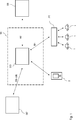
In
Zu jedem einzelnen Fahrzeug
Das Steuersystem CO kommuniziert gemäß
Darüber hinaus ist in der Infrastruktur der
Ein Ziel der Infrastruktur der
Da die Reaktionszeiten der Fahrzeuge auf die ersten Befehle B1 sehr unterschiedlich und unter Umständen auch sehr lange sein können, wird im Rahmen der hier beschriebenen Ausführungsform ferner die aufgenommene oder abgegebene Leistung des Batteriespeichers über die zweiten Befehle B2 angepasst, um hierdurch eine schnelles und genaues Einstellen der Leistungsreduktion auf den Leistungsbetrag LB des Reduktionsbefehls RB zu erreichen, wie nachfolgend anhand von
Gemäß Schritt S1 der
Um eine schnelle Verminderung der Leistung um den Leistungsbetrag LB zu erreichen, wird in Schritt S3 in vorbestimmten Zeitabständen ein Leistungswert LW durch das Steuersystem CO ermittelt. Wie bereits weiter oben erläutert, setzt sich dieser Leistungswert zusammen aus der (aktuell vorliegenden) Verringerung der Gesamtleistungsaufnahme der Antriebsbatterien der Fahrzeuge des Fahrzeugpools und des Batteriespeichers im Vergleich zur Gesamtleistungsaufnahme beim Aussenden der ersten Befehle B1 zuzüglich der (aktuell vorliegenden) Erhöhung der Gesamtleistungsabgabe der Antriebsbatterien der Fahrzeuge des Fahrzeugpools und des Batteriespeichers im Vergleich zur Gesamtleistungsabgabe beim Aussenden der ersten Befehle. Die Ermittlung des Leistungswerts LW erfolgt basierend auf Messwerten von entsprechenden Messgeräten in den Antriebsbatterien der Fahrzeuge
Im Rahmen einer Regelung gemäß Schritt S4 der
Die soeben beschriebene Variante des erfindungsgemäßen Verfahrens greift im Rahmen der Regelung nur auf einen einzelnen Batteriespeicher SB zurück. Alternativ können jedoch auch mehrere solcher Batteriespeicher und gegebenenfalls auch andere elektrische Einheiten zur Energieerzeugung bzw. zum Energieverbrauch genutzt werden, sofern diese eine höhere Reaktionszeit für eine Leistungsanpassung im Vergleich zu den Fahrzeugen aufweisen. The just described variant of the method according to the invention only uses a single battery storage SB within the scope of the regulation. Alternatively, however, it is also possible to use a plurality of such battery storages and optionally also other electrical units for energy generation or energy consumption, provided that they have a higher reaction time for a power adaptation in comparison with the vehicles.
Die im Vorangegangenen beschriebenen Ausführungsformen der Erfindung weisen eine Reihe von Vorteilen auf. Insbesondere wird die Steuerung des Ladens eines Pools von Fahrzeugen über ein gemeinsames Steuersystem derart ermöglicht, dass schnell und genau auf Anforderungen eines Stromnetzbetreibers bezüglich einer Leistungsreduzierung reagiert werden kann. Dabei werden neben fahrzeugseitigen Energiespeichern auch eine oder mehrere weitere elektrische Einheiten mit schnellen Reaktionszeiten genutzt. The embodiments of the invention described above have a number of advantages. In particular, the control of charging a pool of vehicles via a common control system is enabled to respond quickly and accurately to power grid operator requirements for power reduction. In addition to vehicle-side energy storage, one or more further electrical units with fast reaction times are used.
BezugszeichenlisteLIST OF REFERENCE NUMBERS
- 1 1
- Elektrofahrzeug electric vehicle
- 2 2
- Smartphone Smartphone
- CO CO
- zentrale Steuereinheit central control unit
- SE, SE' SE, SE '
- Server server
- SB SB
- stationärer Batteriespeicher stationary battery storage
- PT PT
- Portal portal
- RB RB
- Reduktionsbefehl reduction command
- LB LB
- Leistungsbetrag amount of power
- LW LW
- Leistungswert power value
- B1 B1
- erste Befehle first commands
- B2 B2
- zweite Befehle second commands
Claims (8)
Priority Applications (4)
| Application Number | Priority Date | Filing Date | Title |
|---|---|---|---|
| DE102016202808.1A DE102016202808A1 (en) | 2016-02-24 | 2016-02-24 | Method for controlling the electrical charging of a group of vehicles |
| PCT/EP2016/079919 WO2017144136A1 (en) | 2016-02-24 | 2016-12-06 | Method for controlling the electrical charging of a group of vehicles |
| CN201680078394.XA CN108602442B (en) | 2016-02-24 | 2016-12-06 | Method for controlling electrical charging of a vehicle group |
| US16/109,882 US11072244B2 (en) | 2016-02-24 | 2018-08-23 | Method for controlling the electrical charging of a group of vehicles |
Applications Claiming Priority (1)
| Application Number | Priority Date | Filing Date | Title |
|---|---|---|---|
| DE102016202808.1A DE102016202808A1 (en) | 2016-02-24 | 2016-02-24 | Method for controlling the electrical charging of a group of vehicles |
Publications (1)
| Publication Number | Publication Date |
|---|---|
| DE102016202808A1 true DE102016202808A1 (en) | 2017-08-24 |
Family
ID=57590487
Family Applications (1)
| Application Number | Title | Priority Date | Filing Date |
|---|---|---|---|
| DE102016202808.1A Pending DE102016202808A1 (en) | 2016-02-24 | 2016-02-24 | Method for controlling the electrical charging of a group of vehicles |
Country Status (4)
| Country | Link |
|---|---|
| US (1) | US11072244B2 (en) |
| CN (1) | CN108602442B (en) |
| DE (1) | DE102016202808A1 (en) |
| WO (1) | WO2017144136A1 (en) |
Cited By (1)
| Publication number | Priority date | Publication date | Assignee | Title |
|---|---|---|---|---|
| DE102023004988A1 (en) | 2023-12-04 | 2024-09-12 | Mercedes-Benz Group AG | Method for controlling the electrical charging of a group of motor vehicles, computer program product and charging management instance |
Families Citing this family (4)
| Publication number | Priority date | Publication date | Assignee | Title |
|---|---|---|---|---|
| KR102814775B1 (en) * | 2018-12-06 | 2025-05-30 | 삼성전자주식회사 | Method for controlling power saving and apparatus thereof |
| DE102019210808A1 (en) * | 2019-07-22 | 2021-01-28 | Volkswagen Aktiengesellschaft | Forward-looking operation of a recharging infrastructure for electric vehicles |
| DE102020106542A1 (en) * | 2020-03-10 | 2021-09-16 | ME Energy - Liquid Electricity GmbH | CHARGING COLUMN |
| CN111490576B (en) * | 2020-05-07 | 2022-03-29 | 广东电网有限责任公司广州供电局 | Charging station power allocation method suitable for demand response |
Family Cites Families (26)
| Publication number | Priority date | Publication date | Assignee | Title |
|---|---|---|---|---|
| US7184903B1 (en) * | 2006-03-16 | 2007-02-27 | Vrb Power Systems Inc. | System and method for a self-healing grid using demand side management techniques and energy storage |
| US7747739B2 (en) * | 2006-08-10 | 2010-06-29 | Gridpoint, Inc. | Connection locator in a power aggregation system for distributed electric resources |
| US7844370B2 (en) | 2006-08-10 | 2010-11-30 | Gridpoint, Inc. | Scheduling and control in a power aggregation system for distributed electric resources |
| US7906937B2 (en) | 2009-06-02 | 2011-03-15 | Coulomb Technologies, Inc. | Overcurrent and ground fault protection in a networked charging station for electric vehicles |
| US8013570B2 (en) | 2009-07-23 | 2011-09-06 | Coulomb Technologies, Inc. | Electrical circuit sharing for electric vehicle charging stations |
| DE102011003993A1 (en) | 2010-02-15 | 2011-08-18 | DENSO CORPORATION, Aichi-pref. | Charge controller and navigation device for a plug-in vehicle |
| US8957634B2 (en) * | 2011-03-15 | 2015-02-17 | Siemens Aktiengesellschaft | Network as automation platform for collaborative E-car charging at the residential premises |
| WO2012149965A1 (en) | 2011-05-04 | 2012-11-08 | Siemens Aktiengesellschaft | Method and apparatus for providing electrical energy |
| WO2012163396A1 (en) | 2011-05-30 | 2012-12-06 | Siemens Aktiengesellschaft | Limiting power or current intensity in charging devices |
| US9000722B2 (en) * | 2011-07-01 | 2015-04-07 | Honda Motor Co., Ltd. | Electric vehicle charging strategy |
| WO2013019989A2 (en) | 2011-08-02 | 2013-02-07 | The Regents Of The University Of California | Intelligent electric vehicle charging system |
| DE102011109422A1 (en) | 2011-08-04 | 2013-02-07 | Daimler Ag | Method for charging a battery of a vehicle |
| JP5942993B2 (en) * | 2011-09-01 | 2016-06-29 | 日本電気株式会社 | Charge control system, charge control method and program |
| US8880235B2 (en) * | 2011-11-15 | 2014-11-04 | Palo Alto Research Center Incorporated | Staggering and feathering of demand response and energy supply change in a managed electrical system |
| JP5680222B2 (en) | 2011-12-27 | 2015-03-04 | 三菱電機株式会社 | Energy management system |
| AU2013220074B2 (en) * | 2012-02-13 | 2015-04-16 | Accenture Global Services Limited | Electric vehicle distributed intelligence |
| DE102012103208A1 (en) | 2012-04-13 | 2013-10-17 | Keba Ag | Method for operating a charging connection device for electric vehicles and corresponding charging connection device |
| JP5680613B2 (en) | 2012-11-27 | 2015-03-04 | トヨタ自動車株式会社 | vehicle |
| DE102013000981A1 (en) | 2013-01-22 | 2014-07-24 | Rwe Ag | Method and system for exchanging charging information between a charging station and a cash register system |
| US10766370B2 (en) | 2013-09-04 | 2020-09-08 | Recargo, Inc. | Managing electric vehicle loads on an electric grid |
| US9409492B2 (en) * | 2014-04-21 | 2016-08-09 | Honda Motor Co., Ltd. | Method for precise demand response and control, and a system thereof |
| CA2871242C (en) | 2014-05-29 | 2020-10-27 | Addenergie Technologies Inc. | Method and system for managing power demand of a plurality of charging stations sharing the same portion of an electrical network |
| CN104078978B (en) * | 2014-07-02 | 2016-01-20 | 江苏大学 | A kind of electric automobile networking primary frequency modulation control method of smart grid-oriented |
| US10065520B2 (en) | 2014-07-11 | 2018-09-04 | The Regents Of The University Of California | System for optimizing electricity use from an electric grid and related method |
| US9789779B2 (en) * | 2014-08-25 | 2017-10-17 | Toyota Jidosha Kabushiki Kaisha | Regional charging control service |
| US9834223B2 (en) | 2015-12-15 | 2017-12-05 | Ford Global Technologies, Llc | Diagnosing and supplementing vehicle sensor data |
-
2016
- 2016-02-24 DE DE102016202808.1A patent/DE102016202808A1/en active Pending
- 2016-12-06 CN CN201680078394.XA patent/CN108602442B/en active Active
- 2016-12-06 WO PCT/EP2016/079919 patent/WO2017144136A1/en not_active Ceased
-
2018
- 2018-08-23 US US16/109,882 patent/US11072244B2/en active Active
Non-Patent Citations (4)
| Title |
|---|
| BMW of North America, LLC: Introducing the BMW i ChargeForward Program; 2015.URL: http://content.bmwusa.com/bmwi_pge/index.htmlArchiviert in http://www.archive.org am 11.02.2016 [abgerufen am 08.11.2016] * |
| BUCHKO, D.J.: BMW i ChargeForward Project Wins 2015 ESNA Innovation Award for Unique EV Battery Second Life Energy Storage System. Press Information; 15.10.2015.URL: https://www.press.bmwgroup.com/usa/article/attachment/T0239042EN_US/333191 [abgerufen am 08.11.2016] * |
| JOHN, J. S.: Itron and ClipperCreek Launch the EV Charger as Virtual Smart Meter. 10.11.2014.URL: https://www.greentechmedia.com/articles/read/itron-and-clippercreek-launch-the-ev-charger-as-virtual-smart-meter [abgerufen am 08.11.2016] * |
| PYPER, J.: Automakers on Second-Life Batteries for the Grid: We Want a Foot in the Door of This Market. 09.11.2015.URL: https://www.greentechmedia.com/articles/read/Automakers-on-Second-Life-Batteries-For-the-Grid-We-Want-a-Foot-in-the-Do [abgerufen am 08.11.2016] * |
Cited By (1)
| Publication number | Priority date | Publication date | Assignee | Title |
|---|---|---|---|---|
| DE102023004988A1 (en) | 2023-12-04 | 2024-09-12 | Mercedes-Benz Group AG | Method for controlling the electrical charging of a group of motor vehicles, computer program product and charging management instance |
Also Published As
| Publication number | Publication date |
|---|---|
| CN108602442A (en) | 2018-09-28 |
| CN108602442B (en) | 2021-10-15 |
| WO2017144136A1 (en) | 2017-08-31 |
| US20180361868A1 (en) | 2018-12-20 |
| US11072244B2 (en) | 2021-07-27 |
Similar Documents
| Publication | Publication Date | Title |
|---|---|---|
| EP3478530B1 (en) | Method for controlling the electric charging process of a group of vehicles in the event of a power reduction | |
| DE102016202808A1 (en) | Method for controlling the electrical charging of a group of vehicles | |
| DE102017118606A1 (en) | Power conversion for low voltage bus in electrified vehicle | |
| DE102018209761A1 (en) | Method for configuring a charging system and charging system for charging the electrical energy store of a vehicle | |
| DE102012216729A1 (en) | System and method for managing electrical loads in a vehicle | |
| EP3814194B1 (en) | Energy optimisation during operation of a rail vehicle fleet | |
| DE102013224349B3 (en) | Method for controlling a hybrid drive of a vehicle and computer program for controlling a hybrid drive of a vehicle | |
| DE102016219726A1 (en) | Method for controlling the electrical charging of a group of vehicles | |
| WO2012163396A1 (en) | Limiting power or current intensity in charging devices | |
| DE102016202813B4 (en) | Method for controlling the electric charging of a group of vehicles | |
| EP2758268A1 (en) | Control device for a dc-to-dc converter of an electrical drive system, and a method for operating a dc-to-dc converter | |
| DE102014206381A1 (en) | Charging system for electric vehicles | |
| EP3031112A2 (en) | System and method for controlling the frequency stability and/or voltage stability of the distribution network | |
| DE102014219416A1 (en) | An energy storage device for a motor vehicle and method for operating an energy storage device | |
| DE102014219889A1 (en) | Vehicle and method for controlling a battery in a vehicle | |
| DE102019127054A1 (en) | Method for providing an electrical supply variable in an electrical supply system and device for carrying out the method | |
| DE102012113051A1 (en) | A method for providing control power for stabilizing an AC power network, comprising an energy storage | |
| WO2016156041A1 (en) | Energy management method for a motor vehicle | |
| DE102011080598B4 (en) | Method for adjusting the power consumption of a plurality of electrical consumers in an on-board power system of a motor vehicle | |
| DE102023116569B3 (en) | Method and system for load control in a local network section of a power grid using ripple control signals | |
| DE102020110155A1 (en) | Battery resistance measuring device | |
| EP3741022B1 (en) | Method and device for controlling a voltage | |
| EP4508733A1 (en) | Method and device for determining a retrieval sequence of operating reserves from a plurality of installations for providing a total operating reserve | |
| EP3560056B1 (en) | Central accumulator and control technology with energy management | |
| DE102016217748A1 (en) | Provision of primary control power |
Legal Events
| Date | Code | Title | Description |
|---|---|---|---|
| R012 | Request for examination validly filed | ||
| R016 | Response to examination communication | ||
| R016 | Response to examination communication |