DE102016123741A1 - Method for detecting a mechanical blockage during operation of an electric motor - Google Patents
Method for detecting a mechanical blockage during operation of an electric motor Download PDFInfo
- Publication number
- DE102016123741A1 DE102016123741A1 DE102016123741.8A DE102016123741A DE102016123741A1 DE 102016123741 A1 DE102016123741 A1 DE 102016123741A1 DE 102016123741 A DE102016123741 A DE 102016123741A DE 102016123741 A1 DE102016123741 A1 DE 102016123741A1
- Authority
- DE
- Germany
- Prior art keywords
- electric motor
- bemf
- current
- speed
- detecting
- Prior art date
- Legal status (The legal status is an assumption and is not a legal conclusion. Google has not performed a legal analysis and makes no representation as to the accuracy of the status listed.)
- Pending
Links
- 238000000034 method Methods 0.000 title claims abstract description 38
- 238000001514 detection method Methods 0.000 claims description 18
- 230000005540 biological transmission Effects 0.000 claims description 10
- 230000001419 dependent effect Effects 0.000 claims description 5
- 230000009467 reduction Effects 0.000 claims description 2
- 238000009795 derivation Methods 0.000 claims 1
- 239000012071 phase Substances 0.000 description 34
- 230000000903 blocking effect Effects 0.000 description 16
- 238000005259 measurement Methods 0.000 description 9
- 230000007423 decrease Effects 0.000 description 5
- 238000004804 winding Methods 0.000 description 5
- 238000004519 manufacturing process Methods 0.000 description 4
- 238000007796 conventional method Methods 0.000 description 3
- 230000002093 peripheral effect Effects 0.000 description 3
- 230000006399 behavior Effects 0.000 description 2
- 230000008859 change Effects 0.000 description 2
- 230000001276 controlling effect Effects 0.000 description 2
- 238000010586 diagram Methods 0.000 description 2
- 230000004907 flux Effects 0.000 description 2
- 230000008569 process Effects 0.000 description 2
- 230000001105 regulatory effect Effects 0.000 description 2
- 238000003860 storage Methods 0.000 description 2
- 239000012072 active phase Substances 0.000 description 1
- 238000005452 bending Methods 0.000 description 1
- 230000008901 benefit Effects 0.000 description 1
- 230000033228 biological regulation Effects 0.000 description 1
- 238000001816 cooling Methods 0.000 description 1
- 238000013461 design Methods 0.000 description 1
- 230000000694 effects Effects 0.000 description 1
- 238000005516 engineering process Methods 0.000 description 1
- 239000000446 fuel Substances 0.000 description 1
- 238000010438 heat treatment Methods 0.000 description 1
- 230000010354 integration Effects 0.000 description 1
- 238000005461 lubrication Methods 0.000 description 1
- 230000007257 malfunction Effects 0.000 description 1
- 238000007620 mathematical function Methods 0.000 description 1
- 230000004048 modification Effects 0.000 description 1
- 238000012986 modification Methods 0.000 description 1
- 230000007935 neutral effect Effects 0.000 description 1
- 238000013021 overheating Methods 0.000 description 1
- 230000000737 periodic effect Effects 0.000 description 1
- 230000004044 response Effects 0.000 description 1
- 239000004065 semiconductor Substances 0.000 description 1
- 230000036962 time dependent Effects 0.000 description 1
Images


Classifications
-
- H—ELECTRICITY
- H02—GENERATION; CONVERSION OR DISTRIBUTION OF ELECTRIC POWER
- H02P—CONTROL OR REGULATION OF ELECTRIC MOTORS, ELECTRIC GENERATORS OR DYNAMO-ELECTRIC CONVERTERS; CONTROLLING TRANSFORMERS, REACTORS OR CHOKE COILS
- H02P29/00—Arrangements for regulating or controlling electric motors, appropriate for both AC and DC motors
- H02P29/02—Providing protection against overload without automatic interruption of supply
- H02P29/024—Detecting a fault condition, e.g. short circuit, locked rotor, open circuit or loss of load
- H02P29/0241—Detecting a fault condition, e.g. short circuit, locked rotor, open circuit or loss of load the fault being an overvoltage
-
- H—ELECTRICITY
- H02—GENERATION; CONVERSION OR DISTRIBUTION OF ELECTRIC POWER
- H02H—EMERGENCY PROTECTIVE CIRCUIT ARRANGEMENTS
- H02H7/00—Emergency protective circuit arrangements specially adapted for specific types of electric machines or apparatus or for sectionalised protection of cable or line systems, and effecting automatic switching in the event of an undesired change from normal working conditions
- H02H7/08—Emergency protective circuit arrangements specially adapted for specific types of electric machines or apparatus or for sectionalised protection of cable or line systems, and effecting automatic switching in the event of an undesired change from normal working conditions for dynamo-electric motors
- H02H7/085—Emergency protective circuit arrangements specially adapted for specific types of electric machines or apparatus or for sectionalised protection of cable or line systems, and effecting automatic switching in the event of an undesired change from normal working conditions for dynamo-electric motors against excessive load
Abstract
Die Erfindung betrifft ein Verfahren zum Erkennen einer mechanischen Blockierung im Betrieb eines Elektromotors. Das Verfahren umfasst: das Erfassen einer dem Elektromotor zugeführten elektrischen Stromstärke; das Ermitteln einer Drehzahl des Elektromotors; das Verknüpfen der Stromstärke und der Drehzahl zu einer Kenngröße; und das Erkennen der mechanischen Blockierung, falls die Kenngröße außerhalb eines Sollbereichs liegt.The invention relates to a method for detecting a mechanical blockage during operation of an electric motor. The method comprises: detecting an electric current supplied to the electric motor; determining a rotational speed of the electric motor; linking the current and the speed to a characteristic; and detecting the mechanical lock if the characteristic is outside a desired range.
Description
Gebiet der ErfindungField of the invention
Die Erfindung bezieht sich auf ein Verfahren und eine Vorrichtung zum Erkennen einer mechanischen Blockierung im Betrieb eines Elektromotors.The invention relates to a method and a device for detecting a mechanical blockage during operation of an electric motor.
Hintergrund und Stand der TechnikBackground and state of the art
Der Kraftstoffverbrauch eines Fahrzeugs kann gesenkt werden, indem die Erwärmung des Motors nach dem Start beschleunigt wird und/oder der Luftwiderstand des Fahrzeuges während der Fahrt verringert wird.The fuel consumption of a vehicle can be lowered by speeding up the heating of the engine after take-off and / or reducing the drag of the vehicle while driving.
Zu diesem Zweck können Aktuatoren, beispielsweise ein bürstenloser Gleichstrom-(BLDC-) Motor mit einem mehrstufigen Stirnradgetriebe, eingesetzt werden, um Kühlerklappen eines Fahrzeugs je nach Bedarf zu verstellen. So werden beim Starten des Motors die Kühlerklappen geschlossen, um den Motor schneller zu erwärmen und während der Fahrt entsprechend geöffnet oder geschlossen werden, um beispielsweise den Luftwiderstand zu senken. Zudem kann dadurch die benötigte Kühlung des Motors gesteuert werden.For this purpose, actuators, such as a brushless DC (BLDC) motor with a multi-stage spur gear, can be used to adjust the radiator flaps of a vehicle as needed. Thus, when starting the engine, the radiator flaps are closed to heat the engine faster and be opened or closed accordingly during the ride, for example, to reduce aerodynamic drag. In addition, it can be controlled by the required cooling of the engine.
Ein Aktuator mit einem Elektromotor kann die Kühlerklappen in einem bestimmten Winkel verstellen. Falls der Aktuator den Befehl zur Schließung der Kühlerklappen ausführt, während die Kühlerklappen mechanisch blockiert sind, können sich die Kühlerklappen verbiegen, das Getriebe kann sich aufspannen und der Rotor des Elektromotors kann blockieren. Wenn die mechanische Blockierung nicht rechtzeitig erkannt und der Aktuator weiter angetrieben wird, steigt die vom Aktuator erzeugte Kraft an und es kann zu einer Beschädigung der Kühlerklappen kommen.An actuator with an electric motor can adjust the radiator flaps at a certain angle. If the actuator executes the command to close the radiator flaps while the radiator flaps are mechanically locked, the radiator flaps may flex, the transmission may open, and the rotor of the electric motor may jam. If the mechanical lock is not detected in time and the actuator continues to be driven, the force generated by the actuator increases and damage to the radiator flaps may occur.
Außerdem können das Verbiegen der Kühlerklappen und das Spannen des Getriebes zu einem Zurückschnappen des Rotors des Elektromotors führen. Üblicherweise wird die Anzahl der Kommutierungen gezählt, um die Position des Aktuators zu bestimmen. Beim Zurückschnappen des Rotors gehen Kommutierungen verloren, sodass eine genaue Positionsbestimmung des Aktuators alleine durch Zählen nicht mehr möglich ist. Zur Positionsbestimmung wäre ein Positionssensor nötig, der das System verteuern würde.In addition, bending the radiator flaps and tightening the transmission may cause the rotor of the electric motor to snap back. Usually, the number of commutations is counted to determine the position of the actuator. When snapping back the rotor commutations are lost, so that an exact position determination of the actuator alone by counting is no longer possible. To determine the position, a position sensor would be needed, which would make the system more expensive.
Bei herkömmlichen Verfahren zur Erkennung von mechanischer Blockierung wird beispielsweise ein Grenzwert für eine elektrische Stromstärke bestimmt, die dem Elektromotor des Aktuators zugeführt wird. Diese elektrische Stromstärke wird auch der Einfachheit halber als „Motorstrom“ bezeichnet. Unter der Annahme, dass das vom Elektromotor erzeugte Drehmoment und der Motorstrom direkt proportional zueinander sind, wird einem maximalen Drehmoment ein maximaler Motorstrom zugeordnet.In conventional methods for the detection of mechanical blocking, for example, a limit value for an electric current is determined, which is supplied to the electric motor of the actuator. This electrical current is also referred to as "motor current" for the sake of simplicity. Assuming that the torque generated by the electric motor and the motor current are directly proportional to each other, maximum motor current is associated with maximum torque.
Wenn die Kühlerklappen, oder allgemein ein durch den Aktuator zu verstellende Vorrichtung, z.B. ein Stellglied, mechanisch blockiert sind, steigt das vom Aktuator aufzubringende Drehmoment über ein vordefiniertes Nennmoment hinaus an. Dementsprechend übersteigt auch der Motorstrom einen vordefinierten Motorstrom-Grenzwert. Die mechanische Blockierung kann also erkannt werden, wenn der gemessene Motorstrom oberhalb des Motorstrom-Grenzwertes liegt.If the radiator flaps, or generally a device to be adjusted by the actuator, e.g. an actuator are mechanically blocked, increases the torque applied by the actuator beyond a predefined nominal torque on. Accordingly, the motor current exceeds a predefined motor current limit. The mechanical blockage can therefore be detected if the measured motor current is above the motor current limit value.
Aufgrund von Fluktuationen von Kenngrößen des Elektromotors sowie der Temperatur während des Betriebs ist es allerdings schwierig, einen allgemein gültigen Stromgrenzwert festzulegen. Daher kann ein Ausgleichswert definiert und zu dem Motorstrom-Grenzwert addiert, beziehungsweise subtrahiert werden, um zu verhindern, dass eine mechanische Blockierung fälschlicherweise erkannt wird. Der Ausgleichswert sollte in Echtzeit berechnet und/oder angepasst werden. Dadurch wird das Motorstrom-Grenzwertverfahren verlangsamt.However, due to fluctuations in characteristics of the electric motor and the temperature during operation, it is difficult to set a general current limit. Therefore, a compensation value may be defined and added to the motor current limit, or subtracted, to prevent a mechanical block from being erroneously detected. The compensation value should be calculated and / or adjusted in real time. This slows down the motor current limit method.
Vor diesem Hintergrund besteht eine Aufgabe der Erfindung darin, ein Verfahren bereitzustellen, mit dem eine mechanische Blockierung eines Elektromotors schnell und effektiv, d.h. mit geringer Wahrscheinlichkeit für eine fehlerhafte Erkennung, erkannt werden kann. Die mechanische Blockierung sollte möglichst ohne Sensoren erkannt werden, um Herstellungskosten zu reduzieren.Against this background, an object of the invention is to provide a method by which mechanical locking of an electric motor can be effected quickly and effectively, i. with a low probability of a faulty detection, can be detected. The mechanical blocking should be detected if possible without sensors to reduce manufacturing costs.
Abriss der ErfindungOutline of the invention
Es wird ein Verfahren zum Erkennen einer mechanischen Blockierung im Betrieb eines Elektromotors gemäß Anspruch 1 vorgeschlagen. Gemäß dem Verfahren wird eine dem Elektromotor zugeführte elektrische Stromstärke (d.h. der Motorstrom) erfasst und eine Drehzahl des Elektromotors ermittelt. Die erfasste elektrische Stromstärke sowie die ermittelte Drehzahl werden zu einer Kenngröße verknüpft. Die mechanische Blockierung wird erkannt, falls die Kenngröße außerhalb eines Sollbereichs liegt.A method for detecting a mechanical blockage during operation of an electric motor according to
Der Elektromotor eignet sich, eine bewegliche Vorrichtung, wie z.B. Kühlerklappen eines Fahrzeugmotors, zu verstellen. Insbesondere kann der Elektromotor einen Teil eines Aktuators zum Verstellen der Vorrichtung bilden. Der Elektromotor umfasst in der Regel einen Stator und einen Rotor, die koaxial zueinander angeordnet sind. Der Rotor rotiert relativ zu dem statisch gelagerten Stator. Im Folgenden wird die Drehzahl des Rotors der Einfachheit halber als die Drehzahl des Elektromotors (oder einfach „die Drehzahl“) bezeichnet.The electric motor is suitable for use with a mobile device, such as a mobile device. Radiator flaps of a vehicle engine, to adjust. In particular, the electric motor may form part of an actuator for adjusting the device. The electric motor usually comprises a stator and a rotor, which are arranged coaxially with each other. The rotor rotates relative to the statically supported stator. Hereinafter, the rotational speed of the rotor will be referred to as the rotational speed of the electric motor (or simply "the rotational speed") for the sake of simplicity.
Ferner wird dem Elektromotor ein konstanter oder zeitlich variabler Motorstrom zugeführt, der als elektrische Stromstärke quantifiziert wird. Der Einfachheit halber werden die Begriffe Stromstärke und Motorstrom stellvertretend für die elektrische Stromstärke verwendet.Furthermore, a constant or temporally variable motor current is supplied to the electric motor, which is quantified as electrical current. For the sake of simplicity, the terms amperage and motor current are used to represent the electrical current.
Die Drehzahl des Elektromotors kann um eine oder mehrere Größenordnungen höher sein als die Drehzahl der zu verstellenden Vorrichtung. Hierzu kann ein Getriebe, z.B. ein Stirnradgetriebe, zwischen dem Elektromotor und der Vorrichtung geschaltet sein, um die Drehzahl des Elektromotors herunterzusetzen. Ferner kann das Drehmoment des Elektromotors um den gleichen oder einen ähnlichen Faktor übersetzt werden.The speed of the electric motor may be one or more orders of magnitude higher than the speed of the device to be adjusted. For this purpose, a transmission, e.g. a spur gear, be connected between the electric motor and the device to lower the speed of the electric motor. Furthermore, the torque of the electric motor can be translated by the same or a similar factor.
Eine mechanische Blockierung wird angenommen, wenn die zu verstellende Vorrichtung, oder aber auch der Elektromotor, die verstellende Bewegung nicht oder nicht planmäßig ausführen kann. Eine derartige Blockierung kann beispielsweise durch Verschleiß, Vereisung, Fremdkörper in beweglichen Teilen der Vorrichtung oder des Elektromotors, eine Verformung und/oder eine Fehlfunktion hervorgerufen werden. A mechanical lock is assumed when the device to be adjusted, or even the electric motor, the adjusting movement can not or can not run according to plan. Such a blockage may be caused, for example, by wear, icing, foreign matter in moving parts of the device or the electric motor, deformation and / or malfunction.
Die Drehzahl und die Stromstärke können mathematisch zu der Kenngröße verknüpft werden. Mit anderen Worten, die Kenngröße wird als eine mathematische Funktion abhängig von der Drehzahl und der Stromstärke bestimmt. Beispielsweise wird die Drehzahl durch die Stromstärke dividiert oder umgekehrt. Insbesondere können die Divisionsoperationen durch Schiebeoperationen und Multiplikationen ersetzt werden, die schneller als entsprechende Divisionsoperationen ausgeführt werden können. Alternativ oder zusätzlich wird ein jeweiliger Kehrwert gebildet, um die Rechenoperationen zu beschleunigen. Der Quotient (oder dessen Kehrwert) kann mit weiteren Faktoren multipliziert oder addiert werden, wie später ausführlicher beschrieben wird. In einer alternativen Ausführung wird statt der Drehzahl die gegenelektromotorische Kraft (BEMF) gemessen oder anderweitig ermittelt und in vergleichbarer Weise wie die Drehzahl zur Ermittlung der Kenngröße verwendet.The speed and the current can be mathematically linked to the characteristic. In other words, the characteristic is determined as a mathematical function depending on the speed and the current. For example, the speed is divided by the current or vice versa. In particular, the division operations can be replaced by shift operations and multiplies that can be performed faster than corresponding division operations. Alternatively or additionally, a respective inverse is formed in order to accelerate the arithmetic operations. The quotient (or its reciprocal) may be multiplied or added by other factors, as described in more detail below. In an alternative embodiment, the back electromotive force (BEMF) is measured or otherwise determined instead of the speed and used in a similar manner as the speed for determining the characteristic.
Der Sollbereich umfasst mindestens einen Grenzwert. Falls die Kenngröße diesen Grenzwert, je nach Definition der Kenngröße, unterschreitet oder überschreitet, wird eine mechanische Blockierung erkannt.The target range comprises at least one limit value. If the parameter falls below or exceeds this limit, depending on the definition of the parameter, a mechanical blockage is detected.
Zusätzlich oder alternativ können die Drehzahl und die Stromstärke logisch zu einer anderen oder einer weiteren Kenngröße verknüpft sein. Die Drehzahl und die Stromstärke können demnach über eine UND-Verknüpfung oder über eine ODER-Verknüpfung miteinander verknüpft sein. Beispielsweise kann die Kenngröße angeben, ob erste Anforderungen an die Drehzahl UND, oder ODER, zweite Anforderungen an die Stromstärke erfüllt sind. Demnach umfasst der Sollbereich die ersten und die zweiten Anforderungen.Additionally or alternatively, the rotational speed and the current intensity can be logically linked to another or a further parameter. The rotational speed and the current intensity can therefore be linked to one another via an AND link or via an OR link. For example, the parameter can specify whether first requirements for the speed AND, or OR, second requirements for the current intensity are met. Accordingly, the target range includes the first and the second requirements.
Es ist ferner denkbar, eine mathematische und eine logische Verknüpfung des Motorstroms und der Drehzahl gleichzeitig zu verwenden. In diesem Fall können zwei oder mehr Unterkenngrößen aus unterschiedlichen Verknüpfungen des Motorstroms und der Drehzahl miteinander gebildet werden. Die Unterkenngrößen können über eine mathematische Operation, z.B. eine Multiplikation, oder eine logische Operation, z.B. eine UND-Verknüpfung, gebildet sein. Ferner können die Unterkenngrößen zunächst einzeln mit dem jeweiligen Sollbereich verglichen werden. Die Unterkenngrößen können miteinander zu der Kenngröße verknüpft werden. Die Kenngröße kann mit einem Gesamtsollbereich verglichen werden.It is also conceivable to use a mathematical and a logic combination of the motor current and the speed at the same time. In this case, two or more sub-characteristics may be formed from different combinations of the motor current and the rotational speed with each other. The sub-parameters can be determined via a mathematical operation, e.g. a multiplication, or a logical operation, e.g. an AND link, be formed. Furthermore, the sub-parameters can first be individually compared with the respective target range. The sub-parameters can be linked together to form the characteristic. The parameter can be compared with a total target range.
Das Erfassen der Stromstärke sowie das Ermitteln der Drehzahl können periodisch in einem wiederkehrenden Zyklus erfolgen. In einem Ausführungsbeispiel wird eine Anzahl von aufeinander folgenden Fällen registriert, in welchen die Kenngröße außerhalb des Sollbereichs liegt. Der Elektromotor wird gestoppt, wenn die Anzahl einen voreingestellten Anzahl-Grenzwert überschreitet. In einem alternativen Ausführungsbeispiel wird der Elektromotor gestoppt, sobald bei der Kenngröße eine einzige Überschreitung des Sollbereichs auftritt. Dadurch wird eine mechanische Blockierung beispielsweise sehr schnell erkannt.The detection of the current and the determination of the speed can be done periodically in a recurring cycle. In one embodiment, a number of consecutive cases are registered in which the parameter is outside the target range. The electric motor is stopped when the number exceeds a preset number limit. In an alternative embodiment, the electric motor is stopped as soon as a single overshoot of the desired range occurs in the parameter. As a result, a mechanical blockage is detected very quickly, for example.
Mithilfe des vorgeschlagenen Verfahrens kann eine mechanische Blockierung schnell und effektiv erkannt werden. Dadurch können Schrittverlusten und möglichen Beschädigungen des Elektromotors und/oder der zu verstellenden Vorrichtung vorgebeugt werden. With the proposed method, mechanical obstruction can be detected quickly and effectively. As a result, step losses and possible damage to the electric motor and / or the device to be adjusted can be prevented.
In manchen Ausführungsformen wird ferner eine Zeitdauer zwischen zwei aufeinander folgenden Kommutierungen des Elektromotors erfasst, wobei die Drehzahl proportional zum Kehrwert der Zeitdauer ist. Alternativ kann beispielsweise auch ein einfacher DC-Motor genutzt werden und die Drehzahl mittels eines Sensor oder eines anderen Verfahrens bestimmt werden. Beispielsweise kann die Drehzahl auch ohne zusätzliche Sensoren, über die aufgrund der Drehbewegung des Rotormagneten in den Motorphasen induzierte Spannung, der gegenelektromotorischen Kraft, bestimmt werden.In some embodiments, a time period between two successive commutations of the electric motor is further detected, wherein the rotational speed is proportional to the reciprocal of the time duration. Alternatively, for example, a simple DC motor can be used and the speed can be determined by means of a sensor or another method. For example, the rotational speed can also be determined without additional sensors, on the basis of the rotational movement of the rotor magnet in the motor phases induced voltage, the counterelectromotive force.
Der Elektromotor kann mehrere Phasen umfassen, die, je nach Drehzahl und/oder Drehgeschwindigkeit des Elektromotors, phasenverschoben kommutiert werden. Die Phase des Elektromotors bezieht sich auf einen elektrischen Anschluss, der mit einer oder mehreren Statorspulen einer Statorwicklung gekoppelt ist, und über die die Statorspulen bestromt werden können. Der Begriff Kommutierungen bezieht sich auf einen Vorgang, bei dem der Motorstrom von einer Phase zu einer nächsten Phase des Elektromotors übergeht oder die Polarität des durch eine Phasenwicklung fließenden elektrischen Stroms geändert wird. Beispielsweise kann der Elektromotor eine, zwei oder drei Phasen umfassen. Insbesondere kann der Elektromotor ein dreiphasiger bürstenloser Gleichstrommotor sein. Dabei können die drei Phasen entweder in einer Deltakonfiguration oder in einer Sternkonfiguration miteinander verschaltet sein. Die Bestromung der Phasen kann dann beispielweise durch Schalten von Brückenschaltern einer Brückenschaltung, insbesondere einer H6-Brücke, gesteuert werden. Die Erfindung kann aber auch bei anderen Elektromotoren, beispielsweise bei einem ein- oder zweiphasigen Schrittmotor mit uni- oder bipolarer Bestromung der Phasenwicklungen, verwendet werden. Zur Steuerung der Kommutierung eines zweiphasigen, bipolaren Schrittmotors können beispielsweise zwei H-Brücken mit jeweils vier Halbleiterschaltern verwendet werden.The electric motor may comprise a plurality of phases which, depending on the speed and / or rotational speed of the electric motor, are commutated in phase. The phase of the electric motor refers to an electrical connection which is coupled to one or more stator coils of a stator winding and via which the stator coils can be energized. The term commutations refers to a process in which the motor current passes from one phase to a next phase of the electric motor or the polarity of the electrical current flowing through a phase winding is changed. For example, the electric motor may comprise one, two or three phases. In particular, the electric motor may be a three-phase brushless DC motor. The three phases can be interconnected either in a delta configuration or in a star configuration. The energization of the phases can then be controlled, for example, by switching bridge switches of a bridge circuit, in particular a H6 bridge. However, the invention can also be used in other electric motors, for example in a single-phase or two-phase stepping motor with unipolar or bipolar current supply to the phase windings. To control the commutation of a two-phase, bipolar stepping motor, for example, two H-bridges with four semiconductor switches can be used.
Eine direkte Bestimmung der Drehzahl, z.B. mithilfe von Sensoren, kann kosten- und/oder herstellungstechnisch ungünstig sein. Beispielsweise werden zur direkten Bestimmung der Drehzahl zusätzliche elektronische Bauelemente benötigt, was die Herstellungskosten und den Herstellungsaufwand erhöht und zusätzlich Platz für diese Bauelemente erfordert.A direct determination of the speed, e.g. using sensors, can be unfavorable in terms of cost and / or production technology. For example, additional electronic components are needed for the direct determination of the speed, which increases the manufacturing costs and the production cost and additionally requires space for these components.
Durch die Bestimmung der Zeitdauer kann die Verwendung von Sensoren vermieden werden. Anstatt die Drehzahl direkt zu messen, kann die Zeitdauer zwischen zwei Kommutierungen des Motors erfasst werden, woraus die Drehzahl errechnet werden kann. Die oben genannte Zeitdauer zwischen zwei aufeinander folgenden Kommutierungen kann beispielsweise an einer Stromversorgung für den Elektromotor oder an einer Stromzuführung zu dem Elektromotor gemessen werden.By determining the duration, the use of sensors can be avoided. Instead of measuring the speed directly, the time between two commutations of the motor can be detected, from which the speed can be calculated. The above-mentioned time period between two successive commutations can be measured, for example, at a power supply for the electric motor or at a power supply to the electric motor.
Insbesondere kann die Drehzahl n wie folgt bestimmt werden:

In manchen Ausführungsformen wird eine Nulldurchgangszeit zwischen zwei aufeinander folgenden Nulldurgängen der elektrischen Stromstärke durch eine Phase des Elektromotors erfasst, wobei die Drehzahl proportional zum Kehrwert der Nulldurchgangszeit ist.In some embodiments, a zero-crossing time between two consecutive zero-turns of the electric current is detected by a phase of the electric motor, the speed being proportional to the inverse of the zero-crossing time.
Die Nulldurchgangszeit kann der oben genannten Zeitdauer zwischen zwei aufeinander folgenden Kommutierungen gleichgesetzt werden. Der Motorstrom kann an der Stromversorgung oder an der Stromzuführung zu dem Elektromotor gemessen werden. Dabei kann der jeweilige Durchgang des Motorstroms durch ein von Benutzer definierbares Nullniveau detektiert werden und der zeitliche Abstand zwischen zwei aufeinander folgenden Nulldurchgängen bestimmt werden. Auf diese Weise kann die Drehzahl des Elektromotors bestimmt werden.The zero crossing time can be equated to the above time period between two consecutive commutations. The motor current can be measured at the power supply or at the power supply to the electric motor. In this case, the respective passage of the motor current can be detected by a user definable zero level and the time interval between two consecutive zero crossings are determined. In this way, the rotational speed of the electric motor can be determined.
In manchen Ausführungsformen wird ein Ersatzwiderstand (RBEMF) bestimmt, der proportional zum Quotient der Drehzahl durch die elektrische Stromstärke ist. Der Ersatzwiderstand entspricht dann der Kenngröße. In some embodiments, an equivalent resistance (R BEMF ) is determined which is proportional to the quotient of the rotational speed by the electric current. The equivalent resistance then corresponds to the characteristic.
Die Phasen des Elektromotors können, wie in 
Für die Spannungsamplitude êBEMF der BEMF-Spannung gilt:

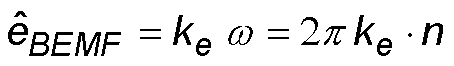
Die Drehzahl n kann, wie oben erläutert, aus der Zeitdauer zwischen zwei Kommutierungen oder aus der Nulldurchgangszeit bestimmt werden.The speed n can, as explained above, be determined from the time duration between two commutations or from the zero-crossing time.
Der Ersatzwiderstand RBEMF entspricht dem Quotient der so bestimmten BEMF-Spannung êBEMF durch die Stromstärke I:
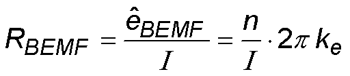
Der Ersatzwiderstand RBEMF ist also proportional zu dem Quotient der Drehzahl n durch die Stromstärke I. Liegt der Ersatzwiderstand RBEMF außerhalb eines vordefinierbaren Sollbereichs, wird eine mechanische Blockierung erkannt. Beispielsweise umfasst der Sollbereich alle Werte oberhalb eines Grenzwertes, sodass eine mechanische Blockierung dann erkannt wird, wenn der Ersatzwiderstand den Grenzwert unterschreitet.The equivalent resistance R BEMF is therefore proportional to the quotient of the rotational speed n due to the current I. If the equivalent resistance R BEMF is outside a predefinable reference range, a mechanical blockage is detected. For example, the target range includes all values above a limit, so that a mechanical blockage is detected when the equivalent resistance falls below the limit.
In manchen Ausführungsformen wird ein Ersatzleitwert (GBEMF) proportional zum Quotient der elektrischen Stromstärke durch die Drehzahl bestimmt, wobei der Ersatzleitwert der Kenngröße entspricht.In some embodiments, a spare conductance (G BEMF ) is determined in proportion to the quotient of the electric current through the speed, the equivalent conductance corresponding to the characteristic.
Wie oben erläutert, gilt n ∝ Δt-1 sowie RBEMF


Multiplikationsoperationen erfordern weniger Rechenzeit und Rechenleistung als Divisionsoperationen. Daher kann das Verfahren weiter beschleunigt werden, indem anstatt des Ersatzwiderstands RBEMF dessen Kehrwert, der Ersatzleitwert GBEMF, bestimmt wird. Für den Sollbereich wird entsprechend ein Kehrwert gebildet.Multiplication operations require less computation time and computational power than division operations. Therefore, the method can be further accelerated by determining, instead of the equivalent resistance R BEMF, its reciprocal, the equivalent conductance G BEMF . For the target range, a reciprocal is formed accordingly.
In manchen Ausführungsformen wird eine zeitliche Ableitung des Ersatzwiderstands aus dem Quotient der Drehzahl durch die elektrische Stromstärke bestimmt. Zusätzlich oder alternativ wird eine zeitliche Ableitung des Ersatzleitwerts aus dem Quotient der elektrischen Stromstärke durch die Drehzahl bestimmt. Die jeweilige zeitliche Ableitung oder beide zeitliche Ableitungen entsprechen der Kenngröße. In some embodiments, a time derivative of the equivalent resistance is determined from the quotient of the speed by the electrical current. Additionally or alternatively, a time derivative of the Ersatzleitwerts from the quotient of the electrical current is determined by the speed. The respective time derivative or both time derivatives correspond to the parameter.
Nicht nur der zeitliche Verlauf des Ersatzwiderstands oder des Ersatzleitwerts, sondern auch ihre jeweilige zeitliche Ableitung kann Auskunft darüber geben, ob eine mechanische Blockierung vorliegt oder nicht. Insbesondere kann die jeweilige zeitliche Ableitung zusätzlich zur Ermittlung der absoluten Werte für den Ersatzwiderstand oder den Ersatzleitwert bestimmt werden, um eine Fehlerquote des Verfahrens, d.h. dass fälschlicherweise eine mechanische Blockierung erkannt wird, zu minimieren.Not only the timing of the equivalent resistance or the equivalent conductance, but also their respective time derivative can provide information as to whether a mechanical blockage exists or not. In particular, the respective time derivative may be determined in addition to the determination of the absolute values for the equivalent resistance or the equivalent conductance in order to determine an error rate of the method, i. that a mechanical blockage is detected by mistake, to minimize.
In manchen Ausführungsformen wird die Kenngröße mit einem Ausgleichswert zur Kompensierung von temperaturabhängigen, zeitabhängigen und/oder betriebszustandsabhängigen Schwankungen eines Wirkungsgrades des Elektromotors multipliziert oder addiert. Es kann beispielsweise vorgesehen sein, dass mehrere Ausgleichswerte in einer Tabelle abgelegt werden. Idealerweise sind die einzelnen Werte der Tabelle einem Temperaturbereich zugeordnet und werden in Echtzeit aus der Tabelle ausgelesen um den Grenzwert anzupassen.In some embodiments, the parameter is multiplied by a compensation value to compensate for temperature-dependent, time-dependent and / or operating state-dependent fluctuations in the efficiency of the electric motor multiplied or added. It can be provided, for example, that several compensation values are stored in a table. Ideally, the individual values of the table are assigned to a temperature range and are read in real time from the table to adjust the limit.
Der Wirkungsgrad η des Elektromotors gibt an, wie effektiv das vom Elektromotor erzeugte Drehmoment Mi auf einen Abtrieb, z.B. die zu verstellende Vorrichtung, übertragen wird. Beispielsweise wird ein Abtriebsmoment Mout bestimmt durch:

In manchen Ausführungsformen erzeugt der Elektromotor im Betrieb ein Rohdrehmoment. Ein Getriebe übersetzt das Rohdrehmoment ins Langsame in einem Untersetzungsverhältnis von zum Beispiel 1:10 bis 1:10000 (entspricht einem Übersetzungsverhältnis von 10:1 bis 10000:1) in ein Nenndrehmoment. Der Sollbereich für die Kenngröße entspricht einem Anstieg des Nenndrehmoments um zum Beispiel bis zu 0,5 Nm, insbesondere bis zu 0,2 Nm oder bis zu 0,1 Nm.In some embodiments, the electric motor generates a raw torque during operation. A transmission translates the raw torque to a low speed in a reduction ratio of, for example, 1:10 to 1: 10,000 (corresponding to a gear ratio of 10: 1 to 10000: 1) in a rated torque. The nominal range for the parameter corresponds to an increase in the rated torque by, for example, up to 0.5 Nm, in particular up to 0.2 Nm or up to 0.1 Nm.
Beispielsweise arbeitet der Elektromotor in einem Drehzahlbereich von 100 bis 10000 Umdrehungen pro Minute und in einem Rohdrehmomentbereich von 10-4 bis 10-2 Nm. Ein Getriebe, das das Rohdrehmoment und die Drehzahl des Elektromotors in das Nenndrehmoment und die Drehzahl der zu verstellenden Vorrichtung übersetzt bzw. untersetzt, arbeitet üblicherweise bei einem Wirkungsgrad von 0,2 bis 0,9.For example, the electric motor operates in a rotational speed range of 100 to 10,000 revolutions per minute and at an Rohdrehmomentbereich from 10 -4 to 10- 2 Nm. A transmission that translates the raw torque and the speed of the electric motor into the rated torque and the speed of the device to be adjusted typically operates at an efficiency of 0.2 to 0.9.
In manchen Ausführungsformen weist der Elektromotor im Betrieb mindestens eine der folgenden Eigenschaften auf: eine Drehmomentkonstante von 1 - 100 mNm/A, eine BEMF-Konstante von 1 - 200 mVs/rad, ein Nenndrehmoment von 0.1 - 50 Nm und eine Drehzahl von 50 - 50000 min-1.In some embodiments, the electric motor has at least one of the following properties during operation: a torque constant of 1 - 100 mNm / A, a BEMF constant of 1 - 200 mVs / rad, a rated torque of 0.1 - 50 Nm and a speed of 50 - 50000 min -1 .
Es sei angemerkt, dass die genannten Werte lediglich Referenzwerte wiedergeben, und keine Einschränkung darstellen.It should be noted that the mentioned values merely represent reference values and are not limiting.
In manchen Ausführungsformen werden die elektrische Stromstärke und die Drehzahl über eine UND-Verknüpfung miteinander verknüpft. Die mechanische Blockierung wird erkannt, falls die Stromstärke außerhalb eines Stromstärkesollbereichs und die Drehzahl außerhalb eines Drehzahlsollbereichs liegen. Dabei kann der Drehzahlsollbereich einen Abfall der Drehzahl um zum Beispiel bis zu 30%, insbesondere bis zu 20% oder bis zu 10%, umfassen. Zusätzlich oder alternativ kann der Stromstärkesollbereich einen Anstieg der elektrischen Stromstärke um bis zu 500 mA, insbesondere bis zu 300 mA oder bis zu 200 mA, umfassen.In some embodiments, the electrical current and speed are ANDed together. The mechanical lock is detected if the current is outside of a nominal range of current and the speed is outside of a target speed range. In this case, the speed setpoint range may include a drop in the speed by, for example, up to 30%, in particular up to 20% or up to 10%. Additionally or alternatively, the desired current range may include an increase of the electrical current by up to 500 mA, in particular up to 300 mA or up to 200 mA.
Gemäß einem weiteren Aspekt der Erfindung wird eine Vorrichtung zum Erkennen einer mechanischen Blockierung im Betrieb eines Elektromotors vorgeschlagen. Die Vorrichtung umfasst eine Stromstärkeerfassungseinheit zum Erfassen einer dem Elektromotor zugeführten elektrischen Stromstärke, eine Drehzahlermittlungseinheit zum Ermitteln einer Drehzahl des Elektromotors, eine Recheneinheit zum Verknüpfen der elektrischen Stromstärke und der Drehzahl zu einer Kenngröße, und eine Vergleichseinheit zum Vergleichen der Kenngröße mit einem oder mehreren Grenzwerten eines Sollbereichs. Die Vorrichtung erkennt die mechanische Blockierung, falls die Kenngröße außerhalb des Sollbereichs liegt.According to a further aspect of the invention, an apparatus for detecting a mechanical blockage in the operation of an electric motor is proposed. The device comprises a current intensity detection unit for detecting an electrical current supplied to the electric motor, a rotational speed determination unit for determining a rotational speed of the electric motor, a computing unit for linking the electric motor electric current and the speed to a characteristic, and a comparison unit for comparing the characteristic with one or more limits of a desired range. The device detects the mechanical blockage, if the parameter is outside the target range.
Die vorgeschlagene Vorrichtung ist geeignet, das Verfahren gemäß Anspruch 1 oder dessen Ausführungsform auszuführen. Die vorgeschlagene Vorrichtung umfasst die strukturellen Merkmale, die zum Ausführen des vorgeschlagenen Verfahrens erforderlich sind.The proposed device is adapted to carry out the method according to
Ferner kann die Vorrichtung zum Beispiel einen 32-Bit ARM Cortex M3 Prozessor mit RISC-Architektur und/oder einen ähnlichen Prozessor umfassen. Unabhängig vom Prozessortyp, ist es vorteilhaft, wenn der Prozessor geeignet ist, die Verknüpfung der Drehzahl und der Stromstärke vorzunehmen und die Kenngröße mit dem jeweiligen Sollwert zu vergleichen. Ferner kann sich der Prozessor eignen, den Elektromotor zu stoppen, falls eine mechanische Blockierung festgestellt wird. Dabei kann die Kommutierung des Motorstroms gestoppt und/oder der Elektromotor abgebremst werden. Beispielsweise kann ein 32-Bit Prozessor, beziehungsweise Controller, des oben genannten Typs eine entsprechende Regelung umsetzen.Further, the device may include, for example, a 32-bit ARM Cortex M3 processor with RISC architecture and / or a similar processor. Regardless of the processor type, it is advantageous if the processor is capable of linking the speed and the current and comparing the characteristic with the respective setpoint. Further, the processor may be capable of stopping the electric motor if a mechanical lock is detected. In this case, the commutation of the motor current can be stopped and / or the electric motor can be braked. For example, a 32-bit processor or controller of the type mentioned above implement a corresponding regulation.
Ein derartiger Controller weist neben einer hohen Rechenleistung auch eine hohe Integrationsdichte von Peripherieeinheiten auf, die speziell für die Ansteuerung von BLDC- und Schrittmotoren geeignet sind. Ein weiterer Vorteil des Controllers liegt darin, dass dieser integrierte Motortreiber besitzt, die direkt an die 12-V-Batteriespannung angeschlossen werden können. Dadurch ist es möglich, BLDC-Motoren ohne zusätzliche Beschaltungsmaßnahmen mit einer 12-V-Spannung anzusteuern.In addition to high computing power, such a controller also has a high integration density of peripheral units, which are especially suitable for driving BLDC and stepper motors. Another advantage of the controller is that it has an integrated motor driver that can be connected directly to the 12V battery voltage. This makes it possible to drive BLDC motors with 12 V voltage without additional wiring.
Mithilfe des vorgeschlagenen Verfahrens sowie der vorgeschlagenen Vorrichtung kann eine mechanische Blockierung schnell und zuverlässig erkannt werden. Dadurch können Beschädigungen des Elektromotors oder der durch den Elektromotor zu verstellenden Vorrichtung vorgebeugt werden.By means of the proposed method and the proposed device, a mechanical blockage can be detected quickly and reliably. As a result, damage to the electric motor or the device to be adjusted by the electric motor can be prevented.
Figurenlistelist of figures
Die Erfindung ist im Folgenden anhand von Beispielen mit Bezug auf die Zeichnungen näher erläutert.
-
1 zeigt eine schematische Darstellung eines Modells für einen Ersatzwiderstand; -
2 zeigt eine schematische Querschnittsansicht eines bürstenlosen Gleichstrom-(BLDC-) Elektromotors; -
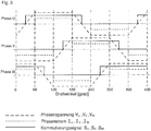
3 zeigt ein schematisches Diagramm von Phasenspannungen, die an den Phasen des Elektromotors von2 anliegen; -
4 zeigt einen zeitlichen Verlauf des Drehmoments eines Elektromotors beim Vorliegen einer mechanischen Blockierung; -
5 zeigt einen zeitlichen Verlauf einer zu einer Phase eines Elektromotors zugeführten Stromstärke bei Vorliegen einer mechanischen Blockierung; -
6 zeigt einen zeitlichen Verlauf der Nulldurchgangszeit eines Elektromotors beim Vorliegen einer mechanischen Blockierung; -
7 zeigt eine schematische Darstellung einer Steuereinheit; -
8 zeigt einen zeitlichen Verlauf des Tastverhältnisses eines Elektromotors beim Vorliegen einer mechanischen Blockierung; -
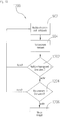
9 zeigt ein Ablaufdiagramm eines Beispiels eines Erkennungsverfahrens einer mechanischen Blockierung; -
10 zeigt ein Ablaufdiagramm einer Abwandlung des Beispiels von9 ; -
11 zeigt ein Ablaufdiagramm eines weiteren Beispiels eines Erkennungsverfahrens einer mechanischen Blockierung; -
12 zeigt ein Ablaufdiagramm eines weiteren Beispiels eines Erkennungsverfahrens einer mechanischen Blockierung; und -
13 zeigt eine schematische Darstellung eines Beispiels einer Steuereinheit zum Steuern eines Elektromotors.
-
1 shows a schematic representation of a model for a replacement resistor; -
2 shows a schematic cross-sectional view of a brushless DC (BLDC) electric motor; -
3 shows a schematic diagram of phase voltages at the phases of the electric motor of2 issue; -
4 shows a time course of the torque of an electric motor in the presence of a mechanical lock; -
5 shows a time course of a supplied to a phase of an electric motor current in the presence of a mechanical lock; -
6 shows a time course of the zero-crossing time of an electric motor in the presence of a mechanical lock; -
7 shows a schematic representation of a control unit; -
8th shows a time course of the duty cycle of an electric motor in the presence of a mechanical lock; -
9 Fig. 10 is a flowchart showing an example of a mechanical blockage detection method; -
10 shows a flowchart of a modification of the example of9 ; -
11 Fig. 10 is a flowchart showing another example of a mechanical blockage detection method; -
12 Fig. 10 is a flowchart showing another example of a mechanical blockage detection method; and -
13 shows a schematic representation of an example of a control unit for controlling an electric motor.
Beschreibung der Beispiele Description of the examples
Im Folgenden wird ein bürstenloser Gleichstrom (BLDC) Elektromotor betrachtet.
Die Phasen
Während des Betriebs des Elektromotors wird der Motorstrom gemessen. Motorstrom, der zwischen Erkennen der mechanischen Blockierung und Stoppen des Elektromotors fließt, ist ein Maß für einen Drehmomentüberschuss des Motors
Schrittverluste entstehen auch durch das Zurückschnappen des Getriebes. Das Zurückschnappen tritt auf, wenn der Motor
Durch das Absinken des Motorstroms kann eine Gegenkraft, die der verbogene Endanschlag auf den Motor ausübt, diejenige Kraft übersteigen, die durch den Motor
Ferner kennzeichnend für die Schnelligkeit eines Erkennungsverfahrens einer mechanischen Blockierung ist eine so genannte Abschaltzeit, d.h. eine Zeitdauer zwischen dem ersten Kontakt mit dem harten Endanschlag und dem Stoppen der Kommutierung durch die Software. Je geringer die Abschaltzeit, desto geringer fallen der Drehmomentüberschuss und ein möglicher Schrittverlust aus.Further characterizing the rapidity of a mechanical blocking detection method is a so-called off time, i. a period of time between the first contact with the hard end stop and the stopping of the commutation by the software. The shorter the turn-off time, the lower the torque surplus and a possible step loss fall out.
In dem gezeigten Beispiel wurde ein herkömmliches Drehzahlabfallverfahren verwendet, bei dem der Elektromotor gestoppt wird, wenn die Drehzahl unter einem voreingestellten Grenzwert fällt. Eine Abweichung des Drehmoments vom Nennmoment um +0,1 Nm wird als das Abschaltmoment definiert. Mit der oben berechneten Steigung ergibt sich, dass das Abschaltmoment nach einer Zeit von 12,5 ms erreicht wird, wenn der Elektromotor blockiert ist. Diese Zeitspanne von 12,5 ms wird als die Sollabschaltzeit definiert.In the example shown, a conventional speed-drop method has been used in which the electric motor is stopped when the speed falls below a preset limit. A deviation of the torque from the nominal torque by +0.1 Nm is defined as the switch-off torque. With the slope calculated above, it follows that the turn-off torque is reached after a time of 12.5 ms when the electric motor is blocked. This period of 12.5 ms is defined as the set-off time.
Wie in
Bei Vorliegen einer mechanischen Blockierung sinkt die Drehzahl des Elektromotors. Wie oben beschrieben, ist die BEMF-Spannung proportional zur Drehzahl des Elektromotors. Daher kann die Blockierung auch anhand der gemessenen BEMF-Spannung erkannt werden. Die BEMF-Spannung kann an einer Phase nur dann gemessen werden, wenn diese nicht bestromt wird. If there is a mechanical blockage, the speed of the electric motor decreases. As described above, the BEMF voltage is proportional to the speed of the electric motor. Therefore, the blockage can also be detected by the measured BEMF voltage. The BEMF voltage can only be measured on a phase if it is not energized.
Aus den Messungen der BEMF-Spannung (nicht gezeigt) ergibt sich, dass die BEMF-Spannung in dem betrachteten Beispiel bei Normalbetrieb des Elektromotors bei 4,9 V liegt. Die BEMF-Spannung sinkt auf 3,7 V, wenn die mechanische Blockierung erkannt wird. Der Abfall der BEMF-Spannung beträgt also 1,2 V.From the measurements of the BEMF voltage (not shown), it can be seen that the BEMF voltage in the example considered is 4.9V during normal operation of the electric motor. The BEMF voltage drops to 3.7 V when the mechanical blockage is detected. The drop in the BEMF voltage is thus 1.2 V.
Innerhalb der Sollabschaltzeit von 12,5 ms steigt die Nulldurchgangszeit um 10 %. Da die Schwankungen der gemessenen Nulldurchgangszeit kleiner als 10 % sind, kann die Nulldurchgangszeit als Indikator für eine Blockiererkennung genutzt werden.Within the set-off time of 12.5 ms, the zero-crossing time increases by 10%. Since the fluctuations in the measured zero-crossing time are less than 10%, the zero-crossing time can be used as an indicator for a blocking detection.
Das Tastverhältnis gibt an, in welchem Verhältnis eine Zeitdauer, innerhalb welcher eine Phase des Elektromotors bestromt wird, zu einer Gesamtzeitdauer steht. Insbesondere ist die Gesamtzeitdauer eine periodische und genormte Zeitdauer, während die bestromte Zeitdauer als eine Impulsdauer verstanden wird. Das Tastverhältnis variiert zwischen 0 %, wenn die Phase nicht bestromt wird, und 100 %, wenn die Phase dauerhaft bestromt wird.The duty cycle indicates the ratio in which a period of time within which a phase of the electric motor is energized is for a total period of time. In particular, the total time period is a periodic and standardized time duration, while the energized time period is understood as a pulse duration. The duty cycle varies between 0% when the phase is not energized and 100% when the phase is energized permanently.
Das Tastverhältnis wird durch eine Steuereinheit
Die Logikeinheit
Bis etwa zum 75. Messpunkt bleibt in dem betrachteten Beispiel das Tastverhältnis
Wird das Verhalten des Tastverhältnisses bis zur Erkennung der Blockierung betrachtet, so ändert es sich in dem betrachteten Beispiel von ca. 37 % zu Beginn der Messung (1. Messpunkt) bis zum Maximum von 40 % beim 190. Messpunkt. Diese Änderung erfolgt innerhalb von etwa 82 ms. Vom Maximum fällt das Tastverhältnis innerhalb von 33 mm auf ca. 28 % ab, bevor der Elektromotor
Deshalb kann die Aktivität des Stromreglers
Zusammengefasst kann eine Blockierung erkannt werden, wenn die BEMF-Spannung unter einen Grenzwert sinkt und/oder wenn die Nulldurchgangszeit einen Grenzwert überschreitet. Ebenso kann eine Blockierung erkannt werden, wenn der Stromregler
Basierend auf den Erkenntnissen sowie dem in
Wie bereits oben gezeigt, lässt sich der Ersatzwiderstand RBEMF berechnen aus:

Im stationären Betrieb ohne Blockierung ist der Widerstand RBEMF konstant. Tritt eine mechanische Blockierung auf, so steigt der Strom I an und die BEMF-Spannung êBEMF sinkt. Damit wird der Abfall des Ersatzwiderstands verstärkt. Der Ersatzwiderstand eignet sich als Indikator für eine Blockierung.In stationary operation without blocking, the resistance R BEMF is constant. If a mechanical blockage occurs, the current I increases and the BEMF voltage ê BEMF drops. This increases the drop in the equivalent resistance. The equivalent resistance is suitable as an indicator of a blockage.
Im Folgenden werden verschiedene Lastfälle betrachtet: ohne Last, mit Last, mit Grenzlast, mit Überlast und Lastfälle, bei denen der Elektromotor gebremst werden muss. Die Überlast entspricht dem Blockierungsfall, weil zum Bewegen der Last ein höheres Drehmoment als das Nennmoment erzeugt werden muss. Bei diesen verschiedenen Lastfällen werden die BEMF-Spannung, die Nulldurchgangszeit, der Motorstrom und das Verhalten des Reglers betrachtet. Aus dem Vergleich der Lastfälle mit dem Überlastfall können die Parameter bei einer Blockierung ermittelt werden.In the following, various load cases are considered: without load, with load, with limit load, with overload and load cases, in which the electric motor must be braked. The overload corresponds to the blocking case, because a higher torque than the rated torque must be generated to move the load. For these different load cases, consider the BEMF voltage, zero-crossing time, motor current and regulator behavior. By comparing the load cases with the overload case, the parameters can be determined in the event of a stall.
Es zeigt sich, dass der Ersatzwiderstand im stationären Betrieb des Elektromotors konstant ist. Auch der Ersatzwiderstand bleibt stets oberhalb eines Grenzwertes. Dieser Grenzwert lässt sich aus der Grenzbelastung bestimmen, denn bei einer Belastung mit Grenzlast erreicht der Motorstrom seinen maximalen Wert, während die Drehzahl vergleichsweise konstant bleibt.It can be seen that the equivalent resistance in stationary operation of the electric motor is constant. Also, the equivalent resistance always remains above a limit. This limit value can be determined from the limit load, because under load with a limit load, the motor current reaches its maximum value while the speed remains relatively constant.
Falls eine Überlast vorliegt, kommt es zu einem Abfall der Drehzahl, da der Motorstrom begrenzt wird und deshalb das erforderliche Drehmoment nicht aufgebracht werden kann. Damit sinken die BEMF-Spannung und somit auch der Ersatzwiderstand.If there is an overload, there is a drop in the speed because the motor current is limited and therefore the required torque can not be applied. This reduces the BEMF voltage and thus the equivalent resistance.
In dem betrachteten Beispiel sei eine Motorkonstante ke von 17,4 mVs/rad, eine Drehzahl n von 2499 min-1 und ein Motorstrom I von 220 mA angenommen. Daraus kann mit den obigen Gleichungen der Ersatzwiderstand-Grenzwert berechnet werden. Zusätzlich kann der Ersatzwiderstand-Grenzwert mit einem Ausgleichswert beaufschlagt sein, um eine Verwechselung von Grenzlast mit einer Blockierung zu vermeiden.In the example considered, assume an engine constant k e of 17.4 mVs / rad, a speed n of 2499 min-1 and a motor current I of 220 mA. From this, the equivalent resistance limit value can be calculated with the above equations. In addition, the equivalent resistance limit value can be subjected to a compensation value in order to avoid a confusion of the limit load with a blockage.
Optional kann ein Zähler eine Anzahl von aufeinander folgenden Fällen registrieren, in denen eine Blockierung erkannt wurde.
Durch die Verwendung des Zählers kann ein fehlerhaftes Erkennen von Blockierungen vermieden werden sowie Schwankungen der Nulldurchgangszeit und des Motorstroms kompensiert werden.By using the counter, a faulty detection of blockages can be avoided and fluctuations in the zero-crossing time and the motor current can be compensated.
Analog zum ersten Ausführungsbeispiel werden die Nulldurchgangszeit ermittelt (902) und der Motorstrom gemessen (904) und daraus der Ersatzwiderstand RBEMF bestimmt (906). Zusätzlich wird die erste Ableitung des Ersatzwiderstands RBEMF nach der Zeit gebildet (nicht gezeigt), die eine Steigung des Ersatzwiderstands RBEMF angibt. Alternativ oder zusätzlich kann der gleiche Prozess mit dem Ersatzleitwert GBEMF durchgeführt werden.Analogous to the first exemplary embodiment, the zero-crossing time is determined (902) and the motor current is measured (904) and the equivalent resistance R BEMF determined therefrom (906). In addition, the first derivative of the equivalent resistance R BEMF is formed after the time (not shown) indicating a slope of the equivalent resistance R BEMF . Alternatively or additionally, the same process can be carried out with the substitute conductance G BEMF .
Der Ersatzwiderstand RBEMF wird mit einem Ersatzwiderstand-Grenzwert verglichen (908). Falls der Ersatzwiderstand RBEMF unter den Ersatzwiderstand-Grenzwert sinkt, wird die Steigung des zeitlichen Verlaufs, d.h. die erste Ableitung nach der Zeit, des Ersatzwiderstandes RBEMF betrachtet (
Wenn der Elektromotor in Grenzlast betrieben wird, unterschreitet der Ersatzwiderstand RBEMF mehrfach den Ersatzwiderstand-Grenzwert aufgrund von Schwankungen der Messwerte, selbst wenn der Ersatzwiderstand RBEMF im Mittel unverändert bleibt. Die Betrachtung des Ersatzwiderstands RBEMF und seiner Steigung macht einen Ausgleichswert überflüssig. Somit kann das Verfahren, insbesondere bei geringeren Lasten, schneller auf eine mechanische Blockierung reagieren.When the electric motor is operated at the limit load, the equivalent resistance R BEMF repeatedly exceeds the equivalent resistance limit value due to variations in the measured values even if the equivalent resistance R BEMF remains unchanged on average. The consideration of the equivalent resistance R BEMF and its slope makes a compensation value superfluous. Thus, the method can respond more quickly to mechanical obstruction, especially at lower loads.
Demnach sind die Nulldurchgangszeit und der Motorstrom über eine UND-Verknüpfung miteinander verknüpft. Die Kenngröße im Sinne des vorgeschlagenen Verfahrens kann durch ein logisches Signal (z.B. „0“ oder „1“) der überprüfenden Einheit (wie z.B. eine Steuereinheit, eine Prozessoreinheit, ein Rechner, oder dergleichen) gebildet sein.Accordingly, the zero crossing time and the motor current are linked via an AND operation. The parameter in the sense of the proposed method can be formed by a logical signal (for example "0" or "1") of the checking unit (such as a control unit, a processor unit, a computer, or the like).
Somit werden Abschaltkriterien bezüglich der Nulldurchgangszeit und bezüglich des Motorstroms über die UND-Verknüpfung miteinander verknüpft. Dadurch ist es möglich, den jeweiligen Grenzwert im Vergleich zu herkömmlichen Verfahren niedrig zu halten, ohne dass Blockierungen fälschlicherweise erkannt werden. Das vorgeschlagene Erkennungsverfahren ist also schneller und gleichzeitig zuverlässig.Thus, shutdown criteria related to the zero crossing time and with respect to the motor current via the AND operation are linked together. This makes it possible to keep the respective limit low compared to conventional methods without falsifications being detected. The proposed recognition method is thus faster and at the same time reliable.
Mit dem beschriebenen Verfahren sowie den Ausführungsformen können Schrittverluste vermieden werden, die Abschaltzeit gegenüber den konventionellen Verfahren verkürzt werden und/oder eine mechanische Blockierung zuverlässig erkannt werden. Ferner funktionieren das Verfahren sowie die Ausführungsformen bei verschiedenen Aktuatorvarianten und weitgehend drehzahlunabhängig.With the method described and the embodiments, step losses can be avoided, the turn-off time can be shortened compared to the conventional methods and / or a mechanical blocking can be reliably detected. Furthermore, the method and the embodiments work with different actuator variants and largely independently of speed.
Somit kann eine mechanische Blockierung schon bei Überschreitung des Nennmoments um +0,1 Nm erkannt werden. Dadurch kann Beschädigungen einer durch den Elektromotor zu verstellenden Vorrichtung, wie z.B. eines Kühlergrills, vorgebeugt werden.Thus, a mechanical blockage can be detected by exceeding the nominal torque by +0.1 Nm. As a result, damage to a device to be adjusted by the electric motor, such as e.g. a radiator grille, to be prevented.
Zudem kann eine Steuereinheit vorgesehen werden, die neben weiteren Peripherieeinheiten für die Ansteuerung von Motoren auch an die Fahrzeugumgebung angepasste Peripherie aufweist.
Die oben genannten Motortreiber sind in
Zur Ansteuerung der Halbbrücken dient das EPWM-Modul
Des Weiteren verfügt die Steuereinheit über das BEMF-Modul
Optional umfasst die Steuereinheit eine Capture-Compare-Einheit (nicht gezeigt),mit Hilfe derer die detektierten Nulldurchgänge als Interrupts registriert werden. Die Capture-Compare-Einheit ist so konfiguriert, dass drei Kanäle parallel gemessen und verarbeitetet werden können. Damit können die Komparatorsignale der Nulldurchgangsmessung im sensorlosen Betrieb oder die Hallsensorsignale im sensorbasierten Betrieb ausgewertet werden.Optionally, the control unit comprises a capture-compare unit (not shown) by means of which the detected zero-crossings are registered as interrupts. The Capture Compare unit is configured so that three channels can be measured and processed in parallel. Thus, the comparator signals of the zero crossing measurement in sensorless operation or the Hall sensor signals can be evaluated in the sensor-based operation.
Optional verfügt die Steuereinheit über eine interne Temperaturüberwachung, die bei Bedarf die Steuereinheit abschaltet, um sie vor Überhitzung durch die Wärmebildung im Elektromotor zu schützen. Die gemessene Temperatur kann mit einem AD/DA-Wandler
Mit Hilfe des AD/DA-Wandlers
Der Speicher
Das LIN-Modul
BezugszeichenlisteLIST OF REFERENCE NUMBERS
- 1111
- Widerstandresistance
- 1212
- Induktivitätinductance
- 1313
- (Ersatz-)Spannungsquelle/BEMF-Spannung(Replacement) voltage source / BEMF voltage
- 2020
- Elektromotor/BLDC-MotorMotor / BLDC motor
- 2121
- Rotorrotor
- 2222
- Statorstator
- 2323
- Magnetmagnet
- 24 - 2624-26
- Zahntooth
- 27 - 2927 - 29
- Statorspulestator
- 6060
- Steuereinheitcontrol unit
- 61, 61', 61"61, 61 ', 61 "
- Motorstrommotor current
- 62, 62', 62"62, 62 ', 62 "
- Drehzahlrotation speed
- 63, 6463, 64
- Knotenpunkt/SubtrahiererNode / subtractor
- 6565
- Stromreglercurrent regulator
- 6666
- DrehzahlreglerSpeed governor
- 6767
- erstes Schaltverhältnisfirst switching ratio
- 6868
- zweites Schaltverhältnissecond switching ratio
- 6969
- Logikeinheitlogic unit
- 7070
- Tastverhältnisduty cycle
- 900900
- Ablaufdiagrammflow chart
- 902 - 910902 - 910
- Verfahrensschrittstep
- 10001000
- Ablaufdiagrammflow chart
- 1002 - 10081002 - 1008
- Verfahrensschrittstep
- 11001100
- Ablaufdiagrammflow chart
- 1102, 11041102, 1104
- Verfahrensschrittstep
- 12001200
- Ablaufdiagrammflow chart
- 1202 - 12061202 - 1206
- Verfahrensschrittstep
- 13101310
- Elektromotorelectric motor
- 13121312
- Getriebetransmission
- 13141314
- Stellgliedactuator
- 13161316
- Steuereinheitcontrol unit
- 13181318
- integrierte Leistungselektronikintegrated power electronics
- 13201320
- EPWM-ModulEPWM module
- 13221322
- BEMF-ModulBEMF module
- 13261326
- CPUCPU
- 13281328
- SpeicherStorage
- 13301330
- AD/DA-WandlerAD / DA converter
- 13321332
- LIN-Modul LIN module
- RR
- Drehachseaxis of rotation
- U, V, WAND MANY MORE
- Phasephase
Claims (15)
Priority Applications (1)
| Application Number | Priority Date | Filing Date | Title |
|---|---|---|---|
| DE102016123741.8A DE102016123741A1 (en) | 2016-12-08 | 2016-12-08 | Method for detecting a mechanical blockage during operation of an electric motor |
Applications Claiming Priority (1)
| Application Number | Priority Date | Filing Date | Title |
|---|---|---|---|
| DE102016123741.8A DE102016123741A1 (en) | 2016-12-08 | 2016-12-08 | Method for detecting a mechanical blockage during operation of an electric motor |
Publications (1)
| Publication Number | Publication Date |
|---|---|
| DE102016123741A1 true DE102016123741A1 (en) | 2018-06-14 |
Family
ID=62201317
Family Applications (1)
| Application Number | Title | Priority Date | Filing Date |
|---|---|---|---|
| DE102016123741.8A Pending DE102016123741A1 (en) | 2016-12-08 | 2016-12-08 | Method for detecting a mechanical blockage during operation of an electric motor |
Country Status (1)
| Country | Link |
|---|---|
| DE (1) | DE102016123741A1 (en) |
Cited By (1)
| Publication number | Priority date | Publication date | Assignee | Title |
|---|---|---|---|---|
| US11511630B2 (en) | 2018-11-01 | 2022-11-29 | Steering Solutions Ip Holding Corporation | Active control of supply current dynamics for synchronous motor drives |
Citations (3)
| Publication number | Priority date | Publication date | Assignee | Title |
|---|---|---|---|---|
| DE102004058679A1 (en) * | 2004-12-06 | 2006-06-14 | Robert Bosch Gmbh | Speed determination in an electrical machine |
| DE102005040290A1 (en) * | 2005-08-19 | 2007-02-22 | Magna Auteca Ag | Drive for the adjustment of flaps |
| DE102012102868A1 (en) * | 2012-04-02 | 2013-10-02 | Minebea Co., Ltd. | Method for operating a brushless electric motor |
-
2016
- 2016-12-08 DE DE102016123741.8A patent/DE102016123741A1/en active Pending
Patent Citations (3)
| Publication number | Priority date | Publication date | Assignee | Title |
|---|---|---|---|---|
| DE102004058679A1 (en) * | 2004-12-06 | 2006-06-14 | Robert Bosch Gmbh | Speed determination in an electrical machine |
| DE102005040290A1 (en) * | 2005-08-19 | 2007-02-22 | Magna Auteca Ag | Drive for the adjustment of flaps |
| DE102012102868A1 (en) * | 2012-04-02 | 2013-10-02 | Minebea Co., Ltd. | Method for operating a brushless electric motor |
Cited By (1)
| Publication number | Priority date | Publication date | Assignee | Title |
|---|---|---|---|---|
| US11511630B2 (en) | 2018-11-01 | 2022-11-29 | Steering Solutions Ip Holding Corporation | Active control of supply current dynamics for synchronous motor drives |
Similar Documents
| Publication | Publication Date | Title |
|---|---|---|
| DE10330809B4 (en) | Engine control unit | |
| EP3428667B1 (en) | Method for obtaining an indication, in particular an initial indication of a possible faulty load condition of a polyphase electric motor | |
| EP0895345B1 (en) | Method for monitoring a collectorless dc motor and motor for performing such a method | |
| EP1657810B1 (en) | Method for the automatic adjustment of the commutation angle of brushless DC motors | |
| DE4132881A1 (en) | Brushless DC motor control circuit - has circuit for phase displacement of commutation times depending on motor speed using functional relationship | |
| WO2008006771A2 (en) | Method and device for determining the positon of the rotor of a brushless and sensorless electric motor | |
| EP2603971B1 (en) | Electronically commutated motor | |
| DE102012102868A1 (en) | Method for operating a brushless electric motor | |
| DE102008058955A1 (en) | Electronically commutated motor | |
| DE112017005029T5 (en) | Control device and method for brushless motor | |
| DE102013114504A1 (en) | Motor control device and driving method of a stepping motor | |
| EP2343797B1 (en) | Single phase electronically commuted motor | |
| DE102016224178A1 (en) | Control of a six-phase PSM | |
| DE102008002339A1 (en) | Excitation timing determination circuit and determination method for an energization timing of an engine | |
| DE102013101976B4 (en) | Motor control and method for detecting stepping errors of a stepping motor | |
| DE102016123741A1 (en) | Method for detecting a mechanical blockage during operation of an electric motor | |
| DE102014212572B4 (en) | Method for obtaining information, in particular initial information on a possible faulty load condition of a polyphase electric motor | |
| EP3413459B1 (en) | Method for detecting a blockage of electrically commutated electric motors | |
| DE102019117818A1 (en) | Device and method for detecting an overload on a brushless DC motor | |
| EP3602772B1 (en) | Method of operation for an electric motor, and soft starter | |
| DE102012110271B4 (en) | Device and method for braking an electric motor | |
| EP2645550B1 (en) | Method and device for controlling an electric machine | |
| EP1443635A1 (en) | Method for driving a firing angle | |
| DE112020001316T5 (en) | Motor drive control device and motor drive control method | |
| DE102013113584A1 (en) | Evaluation device for generating a speed value |
Legal Events
| Date | Code | Title | Description |
|---|---|---|---|
| R163 | Identified publications notified | ||
| R082 | Change of representative |
Representative=s name: BOEHMERT & BOEHMERT ANWALTSPARTNERSCHAFT MBB -, DE |
|
| R012 | Request for examination validly filed | ||
| R016 | Response to examination communication |