DE102016119152A1 - Wind measurement by means of a multicopter - Google Patents
Wind measurement by means of a multicopter Download PDFInfo
- Publication number
- DE102016119152A1 DE102016119152A1 DE102016119152.3A DE102016119152A DE102016119152A1 DE 102016119152 A1 DE102016119152 A1 DE 102016119152A1 DE 102016119152 A DE102016119152 A DE 102016119152A DE 102016119152 A1 DE102016119152 A1 DE 102016119152A1
- Authority
- DE
- Germany
- Prior art keywords
- multicopter
- basis
- unit
- determined
- wind speed
- Prior art date
- Legal status (The legal status is an assumption and is not a legal conclusion. Google has not performed a legal analysis and makes no representation as to the accuracy of the status listed.)
- Granted
Links
- 238000005259 measurement Methods 0.000 title claims abstract description 39
- 238000000034 method Methods 0.000 claims abstract description 24
- 230000005540 biological transmission Effects 0.000 claims abstract description 10
- 230000005484 gravity Effects 0.000 claims abstract description 7
- 239000011159 matrix material Substances 0.000 claims description 13
- 238000012545 processing Methods 0.000 claims description 9
- 230000001276 controlling effect Effects 0.000 claims description 4
- 230000001105 regulatory effect Effects 0.000 claims description 3
- 230000036962 time dependent Effects 0.000 claims description 3
- 238000011161 development Methods 0.000 description 12
- 230000018109 developmental process Effects 0.000 description 12
- 230000006870 function Effects 0.000 description 10
- 230000001133 acceleration Effects 0.000 description 4
- 230000008901 benefit Effects 0.000 description 4
- 238000004590 computer program Methods 0.000 description 4
- 238000001514 detection method Methods 0.000 description 3
- 238000013459 approach Methods 0.000 description 2
- 238000010586 diagram Methods 0.000 description 2
- 238000011156 evaluation Methods 0.000 description 2
- 238000005457 optimization Methods 0.000 description 2
- 238000002940 Newton-Raphson method Methods 0.000 description 1
- 238000013528 artificial neural network Methods 0.000 description 1
- 230000006399 behavior Effects 0.000 description 1
- 230000001419 dependent effect Effects 0.000 description 1
- 238000009795 derivation Methods 0.000 description 1
- 238000009472 formulation Methods 0.000 description 1
- 239000000203 mixture Substances 0.000 description 1
- 230000003287 optical effect Effects 0.000 description 1
- 230000002787 reinforcement Effects 0.000 description 1
- 230000003068 static effect Effects 0.000 description 1
- 230000009466 transformation Effects 0.000 description 1
Images
Classifications
-
- B—PERFORMING OPERATIONS; TRANSPORTING
- B60—VEHICLES IN GENERAL
- B60L—PROPULSION OF ELECTRICALLY-PROPELLED VEHICLES; SUPPLYING ELECTRIC POWER FOR AUXILIARY EQUIPMENT OF ELECTRICALLY-PROPELLED VEHICLES; ELECTRODYNAMIC BRAKE SYSTEMS FOR VEHICLES IN GENERAL; MAGNETIC SUSPENSION OR LEVITATION FOR VEHICLES; MONITORING OPERATING VARIABLES OF ELECTRICALLY-PROPELLED VEHICLES; ELECTRIC SAFETY DEVICES FOR ELECTRICALLY-PROPELLED VEHICLES
- B60L15/00—Methods, circuits, or devices for controlling the traction-motor speed of electrically-propelled vehicles
- B60L15/20—Methods, circuits, or devices for controlling the traction-motor speed of electrically-propelled vehicles for control of the vehicle or its driving motor to achieve a desired performance, e.g. speed, torque, programmed variation of speed
-
- B—PERFORMING OPERATIONS; TRANSPORTING
- B64—AIRCRAFT; AVIATION; COSMONAUTICS
- B64U—UNMANNED AERIAL VEHICLES [UAV]; EQUIPMENT THEREFOR
- B64U10/00—Type of UAV
- B64U10/10—Rotorcrafts
- B64U10/13—Flying platforms
-
- G—PHYSICS
- G01—MEASURING; TESTING
- G01P—MEASURING LINEAR OR ANGULAR SPEED, ACCELERATION, DECELERATION, OR SHOCK; INDICATING PRESENCE, ABSENCE, OR DIRECTION, OF MOVEMENT
- G01P13/00—Indicating or recording presence, absence, or direction, of movement
- G01P13/02—Indicating direction only, e.g. by weather vane
- G01P13/025—Indicating direction only, e.g. by weather vane indicating air data, i.e. flight variables of an aircraft, e.g. angle of attack, side slip, shear, yaw
-
- G—PHYSICS
- G01—MEASURING; TESTING
- G01P—MEASURING LINEAR OR ANGULAR SPEED, ACCELERATION, DECELERATION, OR SHOCK; INDICATING PRESENCE, ABSENCE, OR DIRECTION, OF MOVEMENT
- G01P5/00—Measuring speed of fluids, e.g. of air stream; Measuring speed of bodies relative to fluids, e.g. of ship, of aircraft
-
- G—PHYSICS
- G01—MEASURING; TESTING
- G01W—METEOROLOGY
- G01W1/00—Meteorology
- G01W1/10—Devices for predicting weather conditions
-
- B—PERFORMING OPERATIONS; TRANSPORTING
- B60—VEHICLES IN GENERAL
- B60L—PROPULSION OF ELECTRICALLY-PROPELLED VEHICLES; SUPPLYING ELECTRIC POWER FOR AUXILIARY EQUIPMENT OF ELECTRICALLY-PROPELLED VEHICLES; ELECTRODYNAMIC BRAKE SYSTEMS FOR VEHICLES IN GENERAL; MAGNETIC SUSPENSION OR LEVITATION FOR VEHICLES; MONITORING OPERATING VARIABLES OF ELECTRICALLY-PROPELLED VEHICLES; ELECTRIC SAFETY DEVICES FOR ELECTRICALLY-PROPELLED VEHICLES
- B60L2200/00—Type of vehicles
- B60L2200/10—Air crafts
-
- B—PERFORMING OPERATIONS; TRANSPORTING
- B64—AIRCRAFT; AVIATION; COSMONAUTICS
- B64U—UNMANNED AERIAL VEHICLES [UAV]; EQUIPMENT THEREFOR
- B64U2201/00—UAVs characterised by their flight controls
- B64U2201/10—UAVs characterised by their flight controls autonomous, i.e. by navigating independently from ground or air stations, e.g. by using inertial navigation systems [INS]
-
- B—PERFORMING OPERATIONS; TRANSPORTING
- B64—AIRCRAFT; AVIATION; COSMONAUTICS
- B64U—UNMANNED AERIAL VEHICLES [UAV]; EQUIPMENT THEREFOR
- B64U50/00—Propulsion; Power supply
- B64U50/10—Propulsion
- B64U50/19—Propulsion using electrically powered motors
-
- G—PHYSICS
- G01—MEASURING; TESTING
- G01W—METEOROLOGY
- G01W2201/00—Weather detection, monitoring or forecasting for establishing the amount of global warming
-
- Y—GENERAL TAGGING OF NEW TECHNOLOGICAL DEVELOPMENTS; GENERAL TAGGING OF CROSS-SECTIONAL TECHNOLOGIES SPANNING OVER SEVERAL SECTIONS OF THE IPC; TECHNICAL SUBJECTS COVERED BY FORMER USPC CROSS-REFERENCE ART COLLECTIONS [XRACs] AND DIGESTS
- Y02—TECHNOLOGIES OR APPLICATIONS FOR MITIGATION OR ADAPTATION AGAINST CLIMATE CHANGE
- Y02T—CLIMATE CHANGE MITIGATION TECHNOLOGIES RELATED TO TRANSPORTATION
- Y02T10/00—Road transport of goods or passengers
- Y02T10/60—Other road transportation technologies with climate change mitigation effect
- Y02T10/72—Electric energy management in electromobility
Landscapes
- Engineering & Computer Science (AREA)
- Aviation & Aerospace Engineering (AREA)
- Physics & Mathematics (AREA)
- General Physics & Mathematics (AREA)
- Mechanical Engineering (AREA)
- Remote Sensing (AREA)
- Environmental & Geological Engineering (AREA)
- Ecology (AREA)
- Biodiversity & Conservation Biology (AREA)
- Environmental Sciences (AREA)
- Atmospheric Sciences (AREA)
- Life Sciences & Earth Sciences (AREA)
- Power Engineering (AREA)
- Transportation (AREA)
- Aerodynamic Tests, Hydrodynamic Tests, Wind Tunnels, And Water Tanks (AREA)
- Wind Motors (AREA)
- Feedback Control In General (AREA)
- Arrangements For Transmission Of Measured Signals (AREA)
Abstract
Die Erfindung betrifft einen Multikopter, mit dem Windmessungen durchführbar sind sowie ein Verfahren zur Windmessung mittels eines Multikopters. Der Multikopter umfasst eine Anzahl N Elektromotoren MOTn zum Antrieb von N Propellern PROPn, eine erste Schnittstelle (101) zur Bereitstellung von ersten Parametern P1 umfassend: eine 3D-Position rB des Schwerpunktes B des Multikopters, die Zeitableitungen: r .B und r ..B, eine 3D-Orientierung oM des Multikopters sowie deren Zeitableitung o .M, eine zweite Schnittstelle (102) zur Bereitstellung einer von den Propellern PROPn jeweils aktuell erzeugten aerodynamischen Leistung Pa.n, eine erste Einheit (103), die auf Basis der ersten Parameter P1, auf Basis eines bereitgestellten Modells M1 zur Beschreibung einer Dynamik des Multikopters, und einer auf Basis des Modells M1 ermittelten Schätzung eines auf den Multikopter extern einwirkenden Kraftwinders τe Horizontalkomponenten (vr,x, vr,y) einer Relativgeschwindigkeit des Multikopters zur Luft ermittelt, eine zweite Einheit (104), die auf Basis der ermittelten Horizontalkomponenten (vr,x, vr,y) sowie auf Basis der aerodynamischen Leistung Pa,n die Vertikalkomponente (vr,z) der Relativgeschwindigkeit vr ermittelt, eine dritte Einheit (105), die auf Basis der ermittelten Horizontalkomponenten (vr,x, vr,y), der Vertikalkomponente (vr,z) sowie auf Basis der Parameter P1 die Windgeschwindigkeit vw in einem Inertialsystem ermittelt, sowie eine Speichereinheit (106) zur Speicherung der Windgeschwindigkeiten vw(rB) und/oder eine Übertragungseinheit (107) zur drahtlosen Übertragung der Windgeschwindigkeit vw(rB) an einen Empfänger (108).The invention relates to a multicopter, with which wind measurements can be carried out, and to a method for measuring wind by means of a multicopter. The multicopter comprises a number N of electric motors MOT n for driving N propellers PROP n , a first interface (101) for providing first parameters P1 comprising: a 3D position r B of the center of gravity B of the multicopper, the time derivatives: r. B and r .. B , a 3D orientation o M of the multicopper and their time derivative o. M, a second interface (102) for providing an n of the propellers PROP aerodynamic performance P of each currently generated, a first unit (103) based on the first parameter P1, based on a provided model M1 for describing a dynamic of Multikopter, and an estimated based on the model M1 estimation of an external force acting on the multicopter force wind τ e horizontal components (v r, x , v r, y ) of a relative speed of the multicopter to the air determined, a second unit (104) based on the determined horizontal components (v r, x , v r, y ) and based on the aerodynamic power P a, n determines the vertical component (v r, z ) of the relative velocity v r , a third unit (105) based on the determined Horizontal components (v r, x , v r, y ), the vertical component (v r, z ) and on the basis of the parameters P1 determines the wind speed v w in an inertial system, and a memory unit it (106) for storing the wind speeds v w (r B ) and / or a transmission unit (107) for wireless transmission of the wind speed v w (r B ) to a receiver (108).

Description
Die Erfindung betrifft einen Multikopter, mit dem Windmessungen durchführbar sind, ein Verfahren zur Windmessung mittels eines Multikopters, sowie ein Computersystem, ein digitales Speichermedium, ein Computer-Programm-Produkt, und ein Computerprogramm.The invention relates to a multicopter, with which wind measurements can be carried out, to a method for wind measurement by means of a multi-copter, and to a computer system, a digital storage medium, a computer program product, and a computer program.
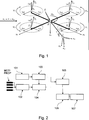
Die vorliegende Erfindung betrifft einen Multikopter, d. h. eine durch mehrere Propeller angetriebene freifliegende Drohne bzw. einen frei fliegenden Roboter, die/der zur Windmessung genutzt wird. Im Stand der Technik sind Multikopter bekannt, die zur Windmessung eingerichtet sind. So geht aus der Veröffentlichung: „Simultaneous Estimation of Aerodynamic and Contact Forces in Flying Robots: Application to Metric Wind Estimations and Collision Detection”, ICRA 2015, Seattle, WA USA May 2015, Seiten: 5290–5296 der vorliegenden Erfinder: Tomic T., und Haddadin S. ein Multikopter hervor, der aufgrund einer Schätzung eines externen auf den Multikopter einwirkenden Kraftwinders τe die Schätzung einer Windgeschwindigkeit ermöglicht. Die Offenbarung dieses Artikels, insbesondere der Kapitel: „III Modeling” und „IV Incorporating Aerodynamics into external Wrench Estimation” wird hiermit explizit in den Offenbarungsgehalt dieser Beschreibung einbezogen.The present invention relates to a multicopter, ie a freeflying drone driven by a plurality of propellers or a free-flying robot which is used for measuring the wind. In the prior art multicopters are known, which are adapted for wind measurement. Thus, the publication: "Simultaneous Estimation of Aerodynamic and Contact Forces in Flying Robots: Application to Metric Wind Estimation and Collision Detection", ICRA 2015, Seattle, WA USA May 2015, pages: 5290-5296 of the present inventor: Tomic T. and Haddadin S. Multikopter one out, allowing the estimation of wind speed based on an estimation of an external force acting on the Multikopter Winders τ e. The disclosure of this article, particularly the chapters: "III Modeling" and "IV Incorporating Aerodynamics into External Wrench Estimation", is hereby explicitly incorporated in the disclosure of this specification.
Die Aufgabe der vorliegenden Erfindung ist es, einen Multikopter bzw. ein Verfahren zum Betrieb eines Multikopters anzugeben, mit dem eine verbesserte Windmessung möglich ist.The object of the present invention is to provide a multicopter or a method for operating a multi-opter, with which an improved wind measurement is possible.
Die Erfindung ergibt sich aus den Merkmalen der unabhängigen Ansprüche. Vorteilhafte Weiterbildungen und Ausgestaltungen sind Gegenstand der abhängigen Ansprüche. Weitere Merkmale, Anwendungsmöglichkeiten und Vorteile der Erfindung ergeben sich aus der nachfolgenden Beschreibung, sowie der Erläuterung von Ausführungsbeispielen der Erfindung, die in den Figuren dargestellt sind.The invention results from the features of the independent claims. Advantageous developments and refinements are the subject of the dependent claims. Other features, applications and advantages of the invention will become apparent from the following description, as well as the explanation of embodiments of the invention, which are illustrated in the figures.
Ein erster Aspekt der Erfindung betrifft einen Multikopter aufweisend: eine Anzahl N Elektromotoren MOTn zum Antrieb von N Propellern PROPn, mit n = 1, 2, ..., N und N ≥ 2, eine erste Schnittstelle zur Bereitstellung von ersten Parametern P1 umfassend: eine 3D-Position rB = (xb, yb, zb) des Schwerpunktes B des Multikopters, die Zeitableitungen: r .B und r ..B, eine 3D-Orientierung oM = (αM, βM, γM) des Multikopters sowie deren Zeitableitung o .M, eine zweite Schnittstelle zur Bereitstellung einer von den Propellern PROPn jeweils aktuell erzeugten aerodynamischen Leistung Pa,n, eine erste Einheit, die auf Basis der ersten Parameter P1, auf Basis eines bereitgestellten Modells M1 zur Beschreibung einer Dynamik des Multikopters, und einer auf Basis des Modells M1 ermittelten Schätzung eines auf den Multikopter extern einwirkenden Kraftwinders τe Horizontalkomponenten (vr,x, vr,y) einer Relativgeschwindigkeit vr:= (vr,x, vr,y, vr,z)T des Multikopters zur Luft ermittelt, eine zweite Einheit, die auf Basis der ermittelten Horizontalkomponenten (vr,x, vr,y) sowie auf Basis der aerodynamischen Leistung Pa,n die Vertikalkomponente (vr,z) der Relativgeschwindigkeit vr ermittelt, eine Einheit, die auf Basis der ermittelten Horizontalkomponenten (vr,x, vr,y der Vertikalkomponente (vr,z) sowie auf Basis der Parameter P1 die Windgeschwindigkeit vw in einem Inertialsystem ermittelt, eine Speichereinheit zur Speicherung der für die Orte rB ermittelten Windgeschwindigkeiten vw(rB) = (vw,x(rB), vw , y(rB), vw , z(rB)) und/oder eine Übertragungseinheit zur drahtlosen Übertragung der Windgeschwindigkeit vw(rB) an einen Empfänger.A first aspect of the invention relates to a multicopter comprising: a number N of electric motors MOT n for driving N propellers PROP n , where n = 1, 2, ..., N and N ≥ 2, a first interface for providing first parameters P1 comprising: a 3D position r B = (x b , y b , z b ) of the center of gravity B of the multicopper, the time derivatives: r. B and r .. B , a 3D orientation o M = (α M , β M , γ M ) of the multicopper and their time derivative o. M , a second interface for providing an aerodynamic power P a, n respectively currently generated by the propellers PROP n , a first unit based on the first parameters P1, on the basis of a provided model M1 for describing a dynamics of the multicopters, and a on the basis of the model M1 estimate of a force winder externally acting on the multicopter τ e horizontal components (v r, x , v r, y ) of a relative velocity v r : = (v r, x , v r, y , v r, z ) T determines the multicopper to the air, a second unit based on the determined horizontal components (v r, x , v r, y ) and based on the aerodynamic power P a, n, the vertical component (v r, z ) of the relative velocity v r determines a unit which determines the wind speed v w in an inertial system on the basis of the determined horizontal components (v r, x , v r, y of the vertical component (v r, z ) and on the basis of the parameters P1, a memory unit r storing the wind speeds v w (r B ) = (v w, x (r B ), v w , y (r B ), v w , z (r B )) determined for the locations r B and / or a transmission unit for wireless transmission of the wind speed v w (r B ) to a receiver.
Vorteilhaft gilt dabei der Zusammenhang: vr = r .B – vw, mit: vr := (vr,x, vr,y vr,z)T := Relativgeschwindigkeit des Multikopters zur Luft, und vw := (vw,x, vw,y, vw,z )T Windgeschwindigkeit.Advantageously, the following applies: v r = r B - v w , with: v r : = (v r, x , v r, y v r, z ) T : = relative speed of the multicopters to the air, and v w : = ( vw, x , vw, y , vw, z ) T Wind speed.
Der vorgeschlagene Multikopter nutzt somit lediglich zur Ermittlung der Horizontalkomponenten (vr,x, vr,y) der Relativgeschwindigkeit vr den in dem einleitend angegebenen Artikel offenbarten Ansatz, bei dem basierend auf einem Modell zur Dynamik des Multikopters und einer damit erzeugten Schätzung eines extern auf den Multikopter einwirkenden Kraftwinders τe eine Schätzung der Relativgeschwindigkeit vr erfolgt.The proposed multicopter therefore uses only the horizontal components ( v.sub.r, x , v.sub.r, y ) of the relative velocity v.sub.r for the approach disclosed in the introductory article in which, based on a model for the dynamics of the multicopper and an estimate thus generated externally acting on the multicopter force winders τ e an estimate of the relative velocity v r takes place.
Die Ermittlung der Vertikalkomponente (vr,z) der Relativgeschwindigkeit vr erfolgt vorliegend auf Basis der Ermittlung der aerodynamischen Leistung der jeweiligen Motor-Propellerkombinationen sowie auf Basis der zuvor ermittelten Horizontalkomponenten (vr,x, vr,y) der Relativgeschwindigkeit vr. Der vorgeschlagene Multikopter ermöglicht dadurch eine genauere und robustere Ermittlung von Windgeschwindigkeiten während des Fluges. Er kann somit insbesondere als fliegender Windsensor eingesetzt werden, der die ermittelten Winddaten an Bord speichert und/oder an eine Bodenstation überträgt.The determination of the vertical component (v r, z ) of the relative velocity v r takes place here on the basis of the determination of the aerodynamic power of the respective engine-propeller combinations and on the basis of the previously determined horizontal components (v r, x , v r, y ) of the relative velocity v r , The proposed multicopter thus enables a more accurate and robust determination of wind speeds during the flight. It can thus be used in particular as a flying wind sensor, which stores the determined wind data on board and / or transmits it to a ground station.
Nachfolgend werden einige Zusammenhänge und mathematische Grundlagen dargestellt, die der Erläuterung und der Umsetzung der Erfindung dienen.In the following some relationships and mathematical basics are presented, which serve to explain and implement the invention.
I. Bewegungsgleichungen (Starrkörpermechanik) I. equations of motion (rigid body mechanics)
Die für den vorliegenden Multikopter geltenden Bewegungsgleichungen können grundsätzlich wie folgt formuliert werden:The equations of motion applicable to the present multicopter can basically be formulated as follows:
(Gl 1)(Eq. 1)
-
mr .. = mge3 + Rf + Rfe mr .. = mge 3 + Rf + Rf e
(Gl 2)(Eq. 2)
-
Iω . = (Iω)xω × ω – mg(rg)×RTe3 + m + m e Iω. = (Iω) × ω × ω -mg (rg) × R T e 3 + m + m e
(Gl 3)(GI 3)
-
R . = R(ω) × R. = R (ω) ×
Dabei seien der von den Propeller-Elektromotoreinheiten erzeugte Soll-Kraftwinder ![]()
![]()
![]()
![]()
![]()
![]()
II. Schätzung des externen KraftwindersII. Estimation of the external dynamo
Die Schätzung des extern auf den Multikopter wirkenden Kraftwinders ![]()

a = RT(r .. – ge3): im Bezugssystem des Multikopters gemessene Beschleunigung
f ^e und ![]()
![]()
a = R T (r .. - ge 3 ): acceleration measured in the reference frame of the multicopter
f and e ![]()
Nähere Ausführungen hierzu ergeben sich bspw. aus dem Artikel von Tomic T., „Evaluation of acceleration-based disturbance Observation for multicopter control” in European Control Conference (ECC), 2014, Seiten 2937–2944.Further details on this can be found, for example, in the article by Tomic T., "Evaluation of acceleration-based disturbance observation for multicopter control" in European Control Conference (ECC), 2014, pages 2937-2944.
III. PropelleraerodynamikIII. propeller aerodynamics
Die auf einen Propeller des Multikopters wirkenden Kräfte hängen von der Freistromgeschwindigkeit v∞ (relative Windgeschwindigkeit) ab. Die Freistromgeschwindigkeit v∞ des n-ten Propellers in einem Bezugssystem des Propellers kann wie folgt ausgedrückt werden:The forces acting on a propeller of the multicopper depend on the free-stream velocity v ∞ (relative wind speed). The free-stream velocity v ∞ of the n-th propeller in a reference system of the propeller can be expressed as follows:
(G15)(G15)
-
v (n) / ∞ = R(n)pb(R(n)bivr + ω × n)v (n) / ∞ = R (n) pb (R (n) biv r + ω × n)
-
wobei vr = r . – vw die wahre Luftgeschwindigkeit des Multikopters, vw die Windgeschwindigkeit,
R (n) / bi R (n) / pb R (n) / bi R (n) / pb
(G16)(G16)
-
T = 2ρAviUT = 2ρAv i U
-
mit: ρ := Luftdichte, A := vom Propeller überstrichene Fläche und U = ||vie3 + v∞||die vom Propeller insgesamt erzeugte Nachlaufströmung. Die vom Propeller induzierte Strömungsgeschwindigkeit v1 kann vorteilhaft wie folgt ermittelt werden: with: ρ: = air density, A: = area swept by the propeller and U = || v i e 3 + v ∞ || the total wake flow generated by the propeller. The flow velocity v 1 induced by the propeller can advantageously be determined as follows:

Vorteilhaft erfolgt die Lösung mittels eines Newton-Raphson-Verfahrens in wenigen Schritten bei bekanntem vh und v∞. Für die horizontale und die vertikale Komponente der Freistromgeschwindigkeit gilt: vxy = v∞ – vz und ![]()
![]()
(Gl 8)(Eq 8)
-
Pa = 2ρAviU(vi – vz)P a = 2ρAv i U (v i -v z )
Die aerodynamische Leistung im Vorwärtsflug bezogen auf die Schwebeflugleistung ist: (G19) Pa/Ph = (vi – vz)/vh gegeben durch
IV. Modell zur Beschreibung eines bürstenlosen DC ElektromotorsIV. Model for describing a brushless DC electric motor
Um die aerodynamische Leistung eine Antriebseinheit abzuschätzen, wird vorteilhaft folgendes dynamische Motor-Modell verwendet.In order to estimate the aerodynamic performance of a drive unit, the following dynamic engine model is advantageously used.


Zusammengefasst bedeutet das, dass der Motorstrom ia gemessen oder geschätzt wird. Die Größen ω und ω . können ebenfalls gemessen oder abhängig von ia geschätzt werden.In summary, this means that the motor current i a is measured or estimated. The quantities ω and ω. can also be measured or estimated depending on i a .
V. Schätzung der Windgeschwindigkeit vw basierend auf der Ermittlung eines externen Kraftwinders τe V. Estimation of the wind speed v w based on the determination of an external power wind τ e
Wie in dem eingangs genannten Artikel ausgeführt, kann die Windgeschwindigkeit basierend auf dem extern auf den Multikopter einwirkenden Kraftwinder τe ermittelt werden. Dabei wird angenommen, dass der Kraftwinder τe sich ausschließlich auf aerodynamische rd Reibungskräfte zurückführen lässt τe = τd, sodass das zugrunde liegende aerodynamische Modell M1 lediglich invertiert werden muss: rd = d(vr). Für einfache aerodynamische Modelle kann dies über eine simple Relation oder Iteration erfolgen. Legt man beispielsweise ein lineares Modell M1 zugrunde, so gilt beispielsweise:As stated in the article mentioned above, the wind speed can be determined based on the externally acting on the multicopter force winder τ e . It is assumed that the force Winder τ e can be attributed solely to aerodynamic r d frictional forces τ s = τ d, so that the aerodynamic underlying model M1 has only to be inverted: r d = d (v r). For simple aerodynamic models, this can be done via a simple relation or iteration. If one uses, for example, a linear model M1, the following applies, for example:
(Gl 15)(Equation 15)
-
d(vr) = DlvrΣω ~i d (v r ) = D l v r Σω i -
mit Dl := lineare Koeffizientenmatrix. Bei Verwendung von fe = d(vr) ergibt sich: mit: D := eine Koeffizientenmatrix. Dieses einfache Modell impliziert weiterhin, dass der Multikopter eine symmetrische Form aufweist.with D l : = linear coefficient matrix. Using f e = d (v r ) we get:
 with: D: = a coefficient matrix. This simple model further implies that the multicopter has a symmetrical shape.
Alternativ kann ein lernbasierter Ansatz verfolgt werden. Die vorstehende Relation kann auch mittels eines Radial-Basis-Funktion (RBF) neuronalen Netzwerks modelliert werden.Alternatively, a learning-based approach can be followed. The above relation can also be modeled by means of a Radial Basis Function (RBF) neural network.
Dies hat den Vorteil, dass die inverse Relation direkt in der Radial-Basis-Funktion codiert ist. Vorteilhaft modelliert man die Relation vr = d–1(τe) als normalisiertes RBF-Netzwerk mit K Basisfunktionen: ![]()

![]()
![]()
![]()
![]()
![]()
VI. Windmessungen auf Basis von ermittelten aerodynamischen Leistungen der Antriebseinheiten jeweils bestehend aus Propeller und ElektromotorVI. Wind measurements based on determined aerodynamic performance of the drive units each consisting of propeller and electric motor
Ausgehend von den Gleichungen (Gl 7), (Gl 8) und (Gl 9) kann die Aerodynamik für einen Propeller als System nichtlinearer Gleichungen F(vr,z, vr,xy, vi, vh, Pa) = 0 und F = [F1, F2, F3]T formuliert werden, mit: 
Es sei unterstellt, dass Pa/(2ρA) und vh bekannt sind und der Vektor x = [vr , x, vr,y, vr,z, vi]T ermittelt werden soll. Das vorstehend angeführte System nichtlinearer Gleichungen (Gl 21) ist unterbestimmt, da drei unbekannte und nur zwei bekannte Größen vorliegen (dabei sind die Horizontalkomponenten vr , x und vr,y in vr,z gekoppelt. Dadurch ergibt sich eine Vielheit von Lösungen des Gleichungssystems (Gl 21). Um dieses Minimierungsproblem zu lösen, wird vorgeschlagen, das System der Gleichungen (Gl 21) derart zu erweitern, dass eine Vielzahl (Anzahl K) von „Messungen” von Pa in das Gleichungssystem integriert wird.Let it be assumed that P a / (2ρA) and v h are known and the vector x = [v r , x , v r, y , v r, z , v i ] T is to be determined. The above system of non-linear equations (Eq 21) is underdetermined because there are three unknown and only two known quantities (in which the horizontal components v r , x and v r, y are coupled in v r, z .) This results in a multiplicity of solutions In order to solve this minimization problem, it is proposed to extend the system of equations (GI 21) in such a way that a multiplicity (number K) of "measurements" of P a is integrated into the system of equations.
Insgesamt werden also K Messungen zur Ermittlung der aerodynamischen Leistung Pa,n durchgeführt. Die aerodynamische Leistung Pa,n kann dabei beispielsweise K-mal für einen einzelnen Elektromotor und dessen Propeller durchgeführt werden. Vorteilhaft erfolgen die K „Messungen” der aerodynamischen Leistung Pa,n für zwei oder mehr unterschiedliche Elektromotoren und deren Propeller. Schließlich erfolgt für die K verschiedenen Messungen eine Transformation des Gleichungssystems (Gl 21) in ein gemeinsames Bezugssystem. Dies erlaubt grundsätzlich die Schätzung aller drei Komponenten der relativen Windrichtung sowie der vom Propeller induzierten Windgeschwindigkeit vi durch Lösen des nichtlinearen quadratischen Minimierungsproblems (Gl 21).Overall, therefore, K measurements for determining the aerodynamic power P a, n are performed. The aerodynamic power P a, n can be carried out K times for a single electric motor and its propeller, for example. Advantageously, the K "measurements" of the aerodynamic power P a, n are made for two or more different electric motors and their propellers. Finally, for the K different measurements, a transformation of the equation system (GI 21) into a common reference system takes place. This basically allows the estimation of all three components of the relative wind direction as well as the wind speed v i induced by the propeller by solving the non-linear quadratic minimization problem (Eq 21).
Dabei wird unterstellt, dass während der K „Messungen” der aerodynamischen Leistung P die Windgeschwindigkeit vw = [vw,x, vw,y, vw,z] gleich bleibt. Werden die K Messungen in einem genügend kurzen Zeitraum durchgeführt, so ist diese Annahme hinreichend berechtigt. Hinreichend genaue Windmessungen erfordern K Ermittlungen der aerodynamischen Leistung, wobei es ausreichend ist K vorteilhaft ≤ 10, oder K vorteilhaft im Bereich von 3 bis 8 zu wählen. Je höher K gewählt wird, desto größer ist der Rechenaufwand und damit einhergehend auch der Zeitraum in dem Messungen durchgeführt werden, sodass mit einem länger werdenden Zeitraum die Wahrscheinlichkeit einer Variation des Windes in dem Zeitraum steigt.It is assumed that during the K "measurements" of the aerodynamic power P, the wind speed v w = [v w, x , v w, y , v w, z ] remains the same. If the K measurements are carried out in a sufficiently short period of time, this assumption is sufficiently justified. Sufficiently accurate wind measurements require K determinations of aerodynamic performance, it being sufficient to choose K advantageously ≤ 10, or K advantageously in the range of 3 to 8. The higher K is chosen, the greater the computational effort and thus as well as the period in which measurements are carried out, so that with an increasing period the probability of a variation of the wind in the period increases.
Vorteilhaft werden an den N Elektromotor-Propellereinheiten gleichzeitig N Messungen bzw. Ermittlungen der aerodynamischen Leistung Pa durchgeführt. Wird beispielsweise K = 8 gewählt und besitzt der Multikopter vier Antriebseinheiten, so werden je Antriebseinheit nur zwei nacheinander folgende „Messungen” der aerodynamischen Leistung Pa benötigt. Vorteilhaft können „Messungen” der aerodynamischen Leistung Pa von einer Vielzahl von Posen des Multikopters zu unterschiedlichen Zeitpunkten in einem kleinen Zeitfenster kombiniert werden. Sofern der Flug des Multikopters nicht aggressiv ist, d. h. dass die Orientierung des Multikopters sich im Messzeitraum nicht signifikant ändert, kann die Freistromgeschwindigkeit v∞ im Bezugssystem des Multikopters hinreichend genau geschätzt werden. Insgesamt werden also K „Messungen” der aerodynamischen Leistung Pa durchgeführt, um vorliegend die Vertikalkomponente [vw,z] der Windrichtung vw zu ermitteln.Advantageously, N measurements or determinations of the aerodynamic power P a are simultaneously carried out on the N electric motor / propeller units. If, for example, K = 8 is selected and the multicopter has four drive units, then only two successive "measurements" of the aerodynamic power P a are required per drive unit. Advantageously, "measurements" of the aerodynamic power P a of a plurality of poses of the multi-opter can be combined at different times in a small time window. If the flight of the multicopper is not aggressive, ie that the orientation of the multicopper does not change significantly during the measurement period, the free-stream velocity v ∞ in the reference frame of the multicopter can be estimated with sufficient accuracy. Overall, therefore, K "measurements" of the aerodynamic power P a are carried out in order to determine the vertical component [v w, z ] of the wind direction v w in the present case.
Der für K Messungen zu ermittelnde Zustandsvektor x ist:The state vector x to be determined for K measurements is:
(Gl 22)(Gl 22)
-
x = [vr,x, vr,y, vr,z, vi,v vi,2, ..., vi,K]x = [v r, x , v r, y , v r, z , v i, v v i, 2 , ..., v i, K ] - wobei das erweiterte Gleichungssystem gelöst werden muss:where the extended system of equations has to be solved:
(Gl 23)(Equation 23)
-
F(vr,x, vr,y, vr,z, vi,1, vh,1, Pa,1, ...vi,K, vh,K, Pa,k) = 0 F = [F1,1, F2,1, F3,1, ..., F1,k, F2,K, F3,K]T F (v r, x , v r, y, v r, z , v i, 1 , v h, 1 , P a, 1 , ..., vi, K, vh, K, P a, k ) = 0 F = [F 1,1 , F 2,1 , F 3,1 , ..., F 1, k , F 2, K , F 3, K ] T
Wobei F1,k, F2,k, F3,k Evaluationen des Gleichungssystems (Gl 21) für die k-te „Messung” der aerodynamischen Leistungen sind. Zur Lösung der Gleichung (Gl 23) ist eine Jacobimatrix erforderlich. Die Jacobimatrix für die k-te Messung ergibt sich zu: 
![]()

![]()
Eine Erweiterung auf K Messungen ist für den Fachmann leicht möglich.An extension to K measurements is easily possible for the expert.
Wenn Messungen von verschiedenen Posen des Multikopters kombiniert werden, müssen die sich jeweils ergebenden Windgeschwindigkeiten in ein gemeinsames Bezugssystem transformiert werden.When combining measurements from different poses of the multicopter, the resulting wind speeds must be transformed into a common frame of reference.
Vorteilhaft wird die Freistromgeschwindigkeit für den n-ten Propeller wie folgt definiert: 
Wobei die transformierten Geschwindigkeiten genutzt werden, um Gleichungen (Gl 21) und (Gl 24) zu berechnen. Die Offset-Geschwindigkeit
Sofern die Gleichungen „matchen”, ist ein multidimensionales Optimierungsproblem zu lösen. Die Lösung liegt dann in dem Schnittpunkt aller nichtlinearen Funktionen, für die gilt: F = 0. Im allgemeinen Fall ergibt sich jedoch kein Schnittpunkt für alle nichtlinearen Funktionen. In diesem Fall muss ein nichtlineares quadratisches Minimierungsproblem gelöst werden mit folgender objektiver Funktion:If the equations "match", a multidimensional optimization problem has to be solved. The solution then lies in the intersection of all nonlinear functions, for which F = 0. In the general case, however, there is no intersection for all nonlinear functions. In this case, a nonlinear quadratic minimization problem must be solved with the following objective function:
(Gl 26)(GI 26)
-
f = 1 / 2FTF.f = 1 / 2F T F.
Dies erfolgt vorteilhafter Weise mit einem Levenberg-Marquard Verfahren. Sofern eine exakte Lösung existiert, gilt f = 0, d. h. dem Schnittpunkt von F = 0. In allen anderen Fällen ergibt sich eine quadratisch minimierte Lösung.This is done advantageously with a Levenberg-Marquard method. If an exact solution exists, f = 0, d. H. at the intersection of F = 0. In all other cases, a quadratically minimized solution results.
Der Lösungsraum von Gleichung (Gl 26) enthält lokale Optima. Basierend auf der zu Grunde liegenden Physik, können dieselben gemessenen aerodynamischen Leistungen Pa bei unterschiedlichen Windgeschwindigkeiten vw und induzierten Geschwindigkeiten vi auftreten. Die optimierten Variablen sind Geschwindigkeiten. Es ist deshalb sinnvoll, physikalische Erwägungen zu Grunde zu legen, um sinnvolle Lösungen von Unsinn von Lösungen zu unterscheiden. Ein Multikopter muss Leistung einsetzen um Schub zu erzeugen, was bedeutet T > 0 und Pa > 0. Die induzierte Geschwindigkeit vi ist kleiner als die Schwebefluggeschwindigkeit vh. Vorteilhaft wird die induzierte Geschwindigkeit auf einen Bereich 0 < vi < vh beschränkt.The solution space of equation (Eq. 26) contains local optima. Based on the underlying physics, the same measured aerodynamic powers P a may occur at different wind speeds v w and induced velocities v i . The optimized variables are speeds. It therefore makes sense to use physical considerations as a basis for distinguishing meaningful solutions from nonsense for solutions. A multicopter must use power to generate thrust, which means T> 0 and P a > 0. The induced velocity v i is less than the hover velocity v h . Advantageously, the induced velocity is restricted to a range 0 <v i <v h .
Eine vorteilhafte Weiterbildung des Multikopters zeichnet sich dadurch aus, dass die zweite Einheit dazu ausgeführt und eingerichtet ist, das folgende nichtlineare quadratische Minimierungsproblem für eine Anzahl von insgesamt K Messungen der aerodynamischen Leistung P für f zu lösen, mit k = 1, ..., K und K ≥ 1: 
An: vom n-ten Propeller überstrichene Fläche,
ρ: Luftdichte,
vh , k(Pa, n , k): induzierte Geschwindigkeit des n-ten Propellers im Schwebeflug zur k-ten Messung,
vi,k(Pa,n,k): vom n-ten Propeller induzierte Geschwindigkeit zur k-ten Messung. An advantageous development of the multicoppler is characterized in that the second unit is designed and arranged to solve the following nonlinear quadratic minimization problem for a number of total K measurements of the aerodynamic power P for f, where k = 1,. K and K ≥ 1:
A n : area swept by the nth propeller,
ρ: air density,
v h , k (P a, n , k ): induced speed of the n-th propeller in hover for k-th measurement,
v i, k (P a, n, k ): velocity induced by the n th propeller for the k th measurement.
Eine vorteilhafte Weiterbildung des Multikopters zeichnet sich dadurch aus, dass die zweite Einheit derart ausgeführt und eingerichtet ist, dass die von der ersten Einheit ermittelten Horizontalkomponenten (vr,x, vr,y) der Relativgeschwindigkeit vr in dem nichtlinearen quadratischen Minimierungsproblem durch folgende Zusammenhänge berücksichtigt wird:An advantageous development of the multicopters is characterized in that the second unit is designed and set up such that the horizontal components (v r, x , v r, y ) determined by the first unit are of the relative velocity v r in the non-linear quadratic minimization problem by the following Considerations:
- (9) F4,k = vr,x,k – vr,x = 0(9) F 4, k = v r, x, k - v r, x = 0
- (10) F5,k = vr,y,k – vr,y = 0.(10) F 5, k = v r, y, k - v r, y = 0.
Eine vorteilhafte Weiterbildung des Multikopters zeichnet sich dadurch aus, dass dem Modell M1 folgende Bewegungsgleichung zugrunde liegt oder das Modell M1 auf folgende Bewegungsgleichung zurückführbar ist:
M: generalisierte Masse des Multikopters
v: generalisierte Geschwindigkeit
ω: Winkelgeschwindigkeit des Multikopters v .: Zeitableitung von v ![]()
J: Blockdiagonale der Jakobimatrix
τ: von den Elektromotoren MOTn zu erzeugender Soll-Kraftwinder [fT, mT]
τe: auf den Multikopter von extern einwirkender Kraftwinder
τd (vr): ausschließlich durch Luftreibung erzeugter externer Kraftwinder
vr: = (vr,x, vr,y, vr,z)T Relativgeschwindigkeit des Multikopters zur Luft
vw: = (vw,x, vw,y, vw,z)T Windgeschwindigkeit.An advantageous development of the multicopper is characterized in that the model M1 is based on the following equation of motion or the model M1 can be traced back to the following equation of motion:
M: generalized mass of the multicopper
v: generalized speed
ω: angular velocity of the multicopter v.: time derivative of v ![]()
J: block diagonal of the Jacobi matrix
τ: desired force winder [f T , m T ] to be generated by the electric motors MOT n
τ e : forcewinder acting on the multicopter externally
τ d (v r ): external force winder generated exclusively by air friction
v r : = (v r, x , v r, y , v r, z ) T Relative speed of the multicopter to the air
v w : = (v w, x , v w, y , v w, z ) T Wind speed.
Eine vorteilhafte Weiterbildung des Multikopters zeichnet sich dadurch aus, dass ein Steuerungssystem zur Steuerung und Regelung der Elektromotoren MOTn vorhanden ist, wobei das Steuerungssystem derart ausgeführt und eingerichtet ist, dass die Elektromotoren MOTn derart geregelt werden, dass die Projektion der ermittelten Windgeschwindigkeit vw auf die Richtung von Drehachsen der Propeller PROPn maximiert wird. Durch diese Maßnahme wird die Genauigkeit der Windmessung erhöht und die Robustheit der Messung verbessert.An advantageous development of the multicopters is characterized in that a control system for controlling and regulating the electric motors MOT n is present, wherein the control system is designed and arranged such that the electric motors MOT n are controlled such that the projection of the determined wind speed v w to the direction of axes of rotation of the propeller PROP n is maximized. This measure increases the accuracy of the wind measurement and improves the robustness of the measurement.
Vorteilhaft sind im Multikopter zur Ermittlung der ersten Parameter P1 ein 3D-Beschleunigungssensor und ein Gyroskop sowie ein Positionsermittlungssystem vorhanden und mit der ersten Schnittstelle verbunden. Vorteilhaft ist das Positionsermittlungssystem ein Satellitennavigationssystem und/oder ein optisches Navigationssystem.Advantageously, in the multicopter for determining the first parameters P1, a 3D acceleration sensor and a gyroscope as well as a position detection system are present and connected to the first interface. Advantageously, the position-finding system is a satellite navigation system and / or an optical navigation system.
Eine vorteilhafte Weiterbildung des Multikopters zeichnet sich dadurch aus, dass zur Ermittlung der aerodynamischen Leistung Pa,n je Elektromotor MOTn ein Motorstromsensor, ein Motordrehzahlsensor oder ein Motordrehzahlschätzer sowie eine Einheit vorhanden ist, die auf Basis eines vorgegebenen Modells M2 zur Beschreibung der Propellerdynamik, der erfassten Motorenströme und – drehzahlen die aerodynamische Leistung Pa,n ermittelt. Zumindest ein entsprechendes Modell M2 wurde vorstehend bereits erläutert.An advantageous development of the multi-coupler is characterized in that for determining the aerodynamic power P a, n per electric motor MOT n a motor current sensor, an engine speed sensor or an engine speed estimator and a unit is present, based on a given model M2 for describing the propeller dynamics, The detected motor currents and speeds determine the aerodynamic power P a, n . At least one corresponding model M2 has already been explained above.
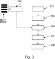
Ein weiterer Aspekt der vorliegenden Erfindung betrifft ein Verfahren zur Messung einer Windgeschwindigkeit vw mit einem Multikopter, wobei der Mutilkopter eine Anzahl N Elektromotoren MOTn zum Antrieb von N Propellern PROPn aufweist, mit n = 1, 2, ...,N und N ≥ 2, mit folgenden Schritten.A further aspect of the present invention relates to a method for measuring a wind speed v w with a multicopter, wherein the mutilkopter has a number N of electric motors MOT n for driving N propellers PROP n , where n = 1, 2,..., N and N ≥ 2, with the following steps.
In einem Schritt erfolgt ein Bereitstellen von ersten zeitabhängigen Parametern P1 umfassend, eine 3D-Position rB = (xb, yb, zb) des Schwerpunktes B des Multikopters, die Zeitableitungen: r .B und r ..B, eine 3D-Orientierung oM = (αM, βM, γM) des Multikopters sowie die Zeitableitung o .M. In einem weiteren Schritt erfolgt ein Bereitstellen einer von den Propellern PROPn jeweils erzeugten aerodynamischen Leistung Pa,n. In einem weiteren Schritt erfolgt auf Basis der ersten Parameter P1, eines bereitgestellten Modells M1 zur Beschreibung einer Dynamik des Multikopters und einer auf Basis des Modells M1 ermittelten Schätzung eines auf den Multikopter extern einwirkenden Kraftwinders τe ein Ermitteln von Horizontalkomponenten (vr,x, vr,y) einer Relativgeschwindigkeit vr des Multikopters zur Luft. In einem weiteren Schritt erfolgt auf Basis der ermittelten Horizontalkomponenten (vr,x, vr,y), der aerodynamischen Leistung Pan ein Ermitteln der Vertikalkomponente (vr,z) der Relativgeschwindigkeit vr. In einem weiteren Schritt erfolgt auf Basis der ermittelten Relativgeschwindigkeit vr = (vr,x, vr,y, vr,z) sowie auf Basis der Parameter P1 ein Ermitteln der Windgeschwindigkeit vw in einem Inertialsystem. Schließlich erfolgt ein Speichern der für rB ermittelten Windgeschwindigkeit: vw(rB) = (vw,x(rB), vw,y(rB), vw,z(rB)) und/oder Übertragen der Windgeschwindigkeit: vw(rB) = (vw,x(rB), vw,y(rB), vw,z(rB)) an einen Empfänger.In one step, provision is made of providing first time-dependent parameters P1, a 3D position r B = (x b , y b , z b ) of the center of gravity B of the multicopper, the time derivatives: r. B and r .. B , a 3D orientation o M = (α M , β M , γ M ) of the multicopters and the time derivative o. M. In a further step, providing an aerodynamic performance in each case generated by the propellers PROP n P a, n is carried out. In a further step, on the basis of the first parameters P1, of a model M1 provided for describing a dynamics of the multicopper and of an estimate of a force winder τ e acting on the multicopter externally, determination of horizontal components (v r, x , v r, y ) a relative velocity v r of the multicopter to the air. In a further step, the aerodynamic power P is used to determine the vertical component (v r, z ) of the relative velocity v r on the basis of the determined horizontal components (v r, x , v r, y ). In a further step, on the basis of the determined relative velocity v r = (v r, x , v r, y , v r, z ) and on the basis of the parameters P1 a determination of the wind speed v w in an inertial system takes place. Finally, the wind speed determined for r B is stored: v w (r B ) = (v w, x (r B ), v w, y ( r B ), v w, z (r B )) and / or transmission wind speed: v w (r B) = (v w, x (r B), v w, y (r B), v w, z (r B)) to a receiver.
Die Horizontalkomponenten (vr,x, vr,y) werden somit durch Messung des extern auf den Multikopter einwirkenden Kraftwinders unter Nutzung der Gleichungen (Gl 16) und (Gl 17) ermittelt. Basierend auf den ermittelten Horizontalkomponenten (vr,x, vr,y) und einer ermittelten aerodynamischen Leistung Pa wird die Vertikalkomponente (vr,z) ermittelt. Durch den Zusammenhang vr = r .B – vw kann schließlich die dreidimensionale Windgeschwindigkeit ermittelt, gespeichert, übertragen und ggf. anschließend ausgegeben werden.The horizontal components (v r, x , v r, y ) are thus determined by measuring the external force acting on the multicopter force winds using equations (Gl 16) and (Gl 17). Based on the determined horizontal components (v r, x , v r, y ) and a determined aerodynamic power P a , the vertical component (v r, z ) is determined. By the connection v r = r. B - v w may eventually determined the three-dimensional wind speed, stored, transmitted and then optionally output.
Eine vorteilhafte Weiterbildung des vorgeschlagenen Verfahrens zeichnet sich dadurch aus, dass das folgende nichtlineare quadratische Minimierungsproblem für eine Anzahl von insgesamt K Messungen der aerodynamischen Leistung Pa,n für f gelöst wird, mit k = 1, 2, ..., K und K ≥ 1:An advantageous development of the proposed method is characterized in that the following nonlinear quadratic minimization problem is solved for a number of total K measurements of the aerodynamic power P a, n for f , where k = 1, 2,..., K and K ≥ 1:
-
(1)
f = 1 / 2FTF f = 1 / 2F T F
-
wobei gilt: mit An: vom n-ten Propeller überstrichene Fläche, p: Luftdichte vh,k(Pa,n,k): induzierte Geschwindigkeit des n-ten Propellers im Schwebeflug zur k-ten Messung, vi,k(Pa,n,k) vom n-ten Propeller induzierte Geschwindigkeit zur k-ten Messung.where:
 with A n : area swept by the nth propeller, p: air density v h, k (P a, n, k ): induced velocity of the n th propeller in hover to the k th measurement, v i, k (P a , n, k ) from the nth propeller-induced speed for the k-th measurement.
Eine vorteilhafte Weiterbildung des vorgeschlagenen Verfahrens zeichnet sich dadurch aus, dass die ermittelten Horizontalkomponenten (vr,x, vr,y) in dem nichtlinearen quadratischen Minimierungsproblem durch folgende Zusammenhänge berücksichtigt werden:
- (9) F4,k = vr,x,k – vr,x – 0
- (10) F5k = vr,y,k – vr,y = 0.
- (9) F 4, k = v r, x, k - v r, x - 0
- (10) F5k = v r, y, k - v r, y = 0.
Eine vorteilhafte Weiterbildung des vorgeschlagenen Verfahrens zeichnet sich dadurch aus, dass dem Modell M1 folgende Bewegungsgleichung zugrunde liegt oder das Modell M1 auf folgende Bewegungsgleichung zurückführbar ist: Mv . + C(v)v + gJTτ + τe wobei gilt: τe = τd(vr) und vr = r .B – vw
M: generalisiert Masse des Multikopters
v: generalisierte Geschwindigkeit
ω: Winkelgeschwindigkeit des Multikopters
v .: Zeitableitung von v ![]()
J: Blockdiagonale Jakobimatrix
τ: von den Elektromotoren MOTn zu erzeugender Soll-Kraftwinder [fT, mT]
τe: auf den Multikopter von extern einwirkender Kraftwinder
τd(vr): ausschließlich durch Luftreibung erzeugter externer Kraftwinder
vr:= (vr,x, vr,y, vr,z)T Relativgeschwindigkeit des Multikopters zur Luft
vw:= (vw,x, vw,y, vw,z)T Windgeschwindigkeit.An advantageous development of the proposed method is characterized in that the model M1 is based on the following equation of motion or the model M1 can be traced back to the following equation of motion: Mv. + C (v) v + gJ T τ + τ e where: τ e = τ d (v r ) and v r = r. B - v w
M: generalizes mass of the multicopper
v: generalized speed
ω: angular velocity of the multicopters
v.: time derivation of v ![]()
J: block diagonal Jacob matrix
τ: desired force winder [f T , m T ] to be generated by the electric motors MOT n
τ e : forcewinder acting on the multicopter externally
τ d (v r ): external force winder generated exclusively by air friction
v r : = (v r, x , v r, y , v r, z ) T Relative speed of the multicopter to the air
v w : = (v w, x , v w, y , v w, z ) T Wind speed.
Eine vorteilhafte Weite des vorgeschlagenen Verfahrens zeichnet sich dadurch aus, dass ein Steuerungssystem zur Steuerung und Regelung der Elektromotoren MOTn vorhanden ist, wobei die Elektromotoren MOTn derart geregelt werden, dass die Projektion der Windgeschwindigkeit vw auf die Richtung der Drehachsen der Propeller maximiert wird.An advantageous width of the proposed method is characterized in that a control system for controlling and regulating the electric motors MOT n is present, wherein the electric motors MOT n are controlled so that the projection of the wind speed v w is maximized to the direction of the axes of rotation of the propeller ,
Eine vorteilhafte Weiterbildung des vorgeschlagenen Verfahrens zeichnet sich dadurch aus, dass zur Ermittlung der aerodynamischen Leistung Pa,n je Elektromotor MOTn ein Motorstrom und eine Motordrehzahl ermittelt wird, und auf Basis eines vorgegebenen Modells M2 zur Beschreibung der Propellerdynamik, der erfassten Motorenströme und -drehzahlen die aerodynamische Leistung Pa,n ermittelt wird.An advantageous development of the proposed method is characterized in that for determining the aerodynamic power P a, n per electric motor MOT n a motor current and an engine speed is determined, and based on a predetermined model M2 for describing the propeller dynamics, the detected motor currents and rotational speeds the aerodynamic power P a, n is determined.
Eine vorteilhafte Weiterbildung des vorgeschlagenen Verfahrens zeichnet sich dadurch aus, dass die Ermittlung der Horizontalkomponenten (vr,x, vr,y) mittels eines Modells des aerodynamischen Kraftwinders, der die Abhängigkeit vr(τe) beschreibt, erfolgt.An advantageous development of the proposed method is characterized in that the determination of the horizontal components (v r, x , v r, y ) by means of a model of the aerodynamic power winders, which describes the dependence v r (τ e ), takes place.
Eine vorteilhafte Weiterbildung des vorgeschlagenen Verfahrens zeichnet sich dadurch aus, dass das nichtlineare quadratische Minimierungsproblem mittels eines nichtlinearen Optimierungsverfahrens (z. B. Levenberg-Marquardt) gelöst wird.An advantageous development of the proposed method is characterized in that the non-linear quadratic minimization problem is solved by means of a nonlinear optimization method (eg Levenberg-Marquardt).
Ein weiterer Aspekt der Erfindung betrifft ein Computersystem mit einer Datenverarbeitungsvorrichtung, wobei die Datenverarbeitungsvorrichtung derart ausgestaltet ist, dass ein Verfahren, wie vorstehend beschrieben, auf der Datenverarbeitungsvorrichtung ausgeführt wird.Another aspect of the invention relates to a computer system having a data processing device, wherein the data processing device is configured such that a method as described above is performed on the data processing device.
Ein weiterer Aspekt der Erfindung betrifft ein digitales Speichermedium mit elektronisch auslesbaren Steuersignalen, wobei die Steuersignale so mit einem programmierbaren Computersystem zusammenwirken können, dass ein Verfahren, wie vorstehend beschrieben, ausgeführt wird.Another aspect of the invention relates to a digital storage medium having electronically readable control signals, wherein the control signals may interact with a programmable computer system such that a method as described above is performed.
Ein weiterer Aspekt der Erfindung betrifft ein Computer-Programm-Produkt mit auf einem maschinenlesbaren Träger gespeichertem Programmcode zur Durchführung des Verfahrens, wie vorstehend beschrieben, wenn der Programmcode auf einer Datenverarbeitungsvorrichtung ausgeführt wird.Another aspect of the invention relates to a computer program product having program code stored on a machine-readable medium for carrying out the method as described above when the program code is executed on a data processing device.
Ein weiterer Aspekt der Erfindung betrifft ein Computer-Programm mit Programmcodes zur Durchführung des Verfahrens, wie vorstehend beschrieben, wenn das Programm auf einer Datenverarbeitungsvorrichtung abläuft. Dazu kann die Datenverarbeitungsvorrichtung als ein beliebiges aus dem Stand der Technik bekanntes Computersystem ausgestaltet sein.A further aspect of the invention relates to a computer program with program codes for carrying out the method, as described above, when the program runs on a data processing device. For this, the data processing device can be configured as any known from the prior art computer system.
Weitere Vorteile, Merkmale und Einzelheiten ergeben sich aus der nachfolgenden Beschreibung, in der – gegebenenfalls unter Bezug auf die Zeichnungen – zumindest ein Ausführungsbeispiel im Einzelnen beschrieben ist. Gleiche, ähnliche und/oder funktionsgleiche Teile sind mit gleichen Bezugszeichen versehen.Further advantages, features and details will become apparent from the following description, in which - where appropriate, with reference to the drawings - at least one embodiment is described in detail. The same, similar and / or functionally identical parts are provided with the same reference numerals.
Es zeigen:Show it:
![]()
![]()
![]()
![]()
![]()
![]()
Der Multikopter umfasst weiterhin eine zweite Einheit
Obwohl die Erfindung im Detail durch bevorzugte Ausführungsbeispiele näher illustriert und erläutert wurde, so ist die Erfindung nicht durch die offenbarten Beispiele eingeschränkt und andere Variationen können vom Fachmann hieraus abgeleitet werden, ohne den Schutzumfang der Erfindung zu verlassen. Es ist daher klar, dass eine Vielzahl von Variationsmöglichkeiten existiert. Es ist ebenfalls klar, dass beispielhaft genannte Ausführungsformen wirklich nur Beispiele darstellen, die nicht in irgendeiner Weise als Begrenzung etwa des Schutzbereichs, der Anwendungsmöglichkeiten oder der Konfiguration der Erfindung aufzufassen sind. Vielmehr versetzen die vorhergehende Beschreibung und die Figurenbeschreibung den Fachmann in die Lage, die beispielhaften Ausführungsformen konkret umzusetzen, wobei der Fachmann in Kenntnis des offenbarten Erfindungsgedankens vielfältige Änderungen beispielsweise hinsichtlich der Funktion oder der Anordnung einzelner, in einer beispielhaften Ausführungsform genannter Elemente vornehmen kann, ohne den Schutzbereich zu verlassen, der durch die Ansprüche und deren rechtliche Entsprechungen, wie etwa weitergehenden Erläuterungen in der Beschreibung, definiert wird.Although the invention has been further illustrated and explained in detail by way of preferred embodiments, the invention is not limited by the disclosed examples, and other variations can be derived therefrom by those skilled in the art without departing from the scope of the invention. It is therefore clear that a multitude of possible variations exists. It is also to be understood that exemplified embodiments are really only examples that are not to be construed in any way as limiting the scope, applicability, or configuration of the invention. Rather, the foregoing description and description of the figures enable one skilled in the art to practice the exemplary embodiments, and those skilled in the art, having the benefit of the disclosed inventive concept, can make various changes, for example, to the function or arrangement of individual elements recited in an exemplary embodiment, without Protection area defined by the claims and their legal equivalents, such as further explanations in the description.
BezugszeichenlisteLIST OF REFERENCE NUMBERS
- 101101
- erste Schnittstellefirst interface
- 102102
- zweite Schnittstellesecond interface
- 103103
- erste Einheitfirst unit
- 104104
- zweite Einheitsecond unit
- 105105
- dritte Einheitthird unit
- 106106
- Speichereinheitstorage unit
- 107107
- Übertragungseinheittransmission unit
- 201–206201-206
- Verfahrensschrittesteps
Claims (10)

Priority Applications (8)
| Application Number | Priority Date | Filing Date | Title |
|---|---|---|---|
| DE102016119152.3A DE102016119152B4 (en) | 2016-10-07 | 2016-10-07 | Wind measurement by means of a multicopter |
| KR1020197013028A KR102279362B1 (en) | 2016-10-07 | 2017-10-09 | Wind measurement using a multicopter |
| EP17793833.9A EP3523661B1 (en) | 2016-10-07 | 2017-10-09 | Wind measurement by means of a multicopter |
| US16/340,018 US11214366B2 (en) | 2016-10-07 | 2017-10-09 | Wind measurement by means of a multicopter |
| PCT/EP2017/001190 WO2018065096A1 (en) | 2016-10-07 | 2017-10-09 | Wind measurement by means of a multicopter |
| DK17793833.9T DK3523661T3 (en) | 2016-10-07 | 2017-10-09 | Wind measurement using a multicopter |
| CN201780061906.6A CN110036298B (en) | 2016-10-07 | 2017-10-09 | Wind measurement with multi-rotor aircraft |
| JP2019518426A JP6754005B2 (en) | 2016-10-07 | 2017-10-09 | Wind speed measurement with multicopter |
Applications Claiming Priority (1)
| Application Number | Priority Date | Filing Date | Title |
|---|---|---|---|
| DE102016119152.3A DE102016119152B4 (en) | 2016-10-07 | 2016-10-07 | Wind measurement by means of a multicopter |
Publications (2)
| Publication Number | Publication Date |
|---|---|
| DE102016119152A1 true DE102016119152A1 (en) | 2018-04-12 |
| DE102016119152B4 DE102016119152B4 (en) | 2018-12-27 |
Family
ID=60245027
Family Applications (1)
| Application Number | Title | Priority Date | Filing Date |
|---|---|---|---|
| DE102016119152.3A Active DE102016119152B4 (en) | 2016-10-07 | 2016-10-07 | Wind measurement by means of a multicopter |
Country Status (8)
| Country | Link |
|---|---|
| US (1) | US11214366B2 (en) |
| EP (1) | EP3523661B1 (en) |
| JP (1) | JP6754005B2 (en) |
| KR (1) | KR102279362B1 (en) |
| CN (1) | CN110036298B (en) |
| DE (1) | DE102016119152B4 (en) |
| DK (1) | DK3523661T3 (en) |
| WO (1) | WO2018065096A1 (en) |
Cited By (1)
| Publication number | Priority date | Publication date | Assignee | Title |
|---|---|---|---|---|
| CN119689016A (en) * | 2025-02-26 | 2025-03-25 | 浙江省水利河口研究院(浙江省海洋规划设计研究院) | Three-dimensional flow velocity measurement device and method based on mechanics |
Families Citing this family (16)
| Publication number | Priority date | Publication date | Assignee | Title |
|---|---|---|---|---|
| WO2021009826A1 (en) * | 2019-07-16 | 2021-01-21 | 株式会社エアロネクスト | Environment information analysis method |
| CN114967736A (en) * | 2019-07-26 | 2022-08-30 | 深圳市道通智能航空技术股份有限公司 | Wind speed measuring and calculating method, wind speed estimator and unmanned aerial vehicle |
| CN111114856B (en) * | 2019-09-24 | 2022-10-28 | 哈尔滨工业大学 | Aerodynamic characteristics measurement device with automatic adjustment of the distance between the upper and lower rotors of the Mars vehicle |
| DE102020107172A1 (en) * | 2020-03-16 | 2021-09-16 | Volocopter Gmbh | A method for controlling an aircraft, a control device for an aircraft and an aircraft with such a control device |
| KR20230010733A (en) * | 2020-05-14 | 2023-01-19 | 프테로다이나믹스 인코포레이티드 | Control of aircraft capable of vertical take-off and landing |
| CN112034200B (en) * | 2020-09-03 | 2022-07-19 | 上海旭宇信息科技有限公司 | Propeller type water flow speed metering device |
| CN112213516A (en) * | 2020-09-22 | 2021-01-12 | 南京信息工程大学 | A wind measurement method for floating platform based on dynamic inversion |
| CN112269031B (en) * | 2020-10-22 | 2022-05-10 | 天津职业技术师范大学(中国职业培训指导教师进修中心) | Neural network-based real-time wind speed estimation method for rotor unmanned aerial vehicle |
| CN112464359B (en) * | 2020-11-03 | 2022-12-06 | 中国直升机设计研究所 | Flight quality modeling and checking method of multi-gyroplane |
| CN112904046B (en) * | 2021-02-10 | 2022-03-18 | 复旦大学 | An air flow monitoring system for aircraft in the atmosphere |
| CN113252933B (en) * | 2021-05-12 | 2022-03-11 | 北京航空航天大学 | A kind of propeller incoming velocity detection device and method |
| CN115145293A (en) * | 2022-06-29 | 2022-10-04 | 广西科技大学 | A kind of wind speed measurement method of multi-rotor unmanned aerial vehicle |
| CN116305772A (en) * | 2022-12-28 | 2023-06-23 | 亿航智能设备(广州)有限公司 | Multi-rotor air speed calculation method, equipment and computer readable storage medium |
| JP2025093573A (en) * | 2023-12-12 | 2025-06-24 | 株式会社日立製作所 | Aircraft Guidance System, Aircraft, Aircraft Management Device, and Aircraft Guidance Method |
| CN118169431B (en) * | 2024-04-11 | 2024-11-26 | 中国科学院空天信息创新研究院 | Method and system for calibrating aircraft anemometer data |
| CN119336049B (en) * | 2024-12-23 | 2025-03-18 | 成都航空职业技术学院 | A method for suppressing dynamic wind disturbance of unmanned aerial vehicles |
Citations (1)
| Publication number | Priority date | Publication date | Assignee | Title |
|---|---|---|---|---|
| US8219267B2 (en) * | 2010-05-27 | 2012-07-10 | Honeywell International Inc. | Wind estimation for an unmanned aerial vehicle |
Family Cites Families (23)
| Publication number | Priority date | Publication date | Assignee | Title |
|---|---|---|---|---|
| US5214596A (en) * | 1986-06-14 | 1993-05-25 | Duetsche Forchungs- Und Versuchsanstalt Fur Luft- Und Raumfahrt E.V. | System for determining the airspeed of helicopters |
| FR2642842B1 (en) * | 1989-01-18 | 1991-05-03 | Crouzet Sa | METHOD FOR DETERMINING THE SPEED OF THE MIDDLE WIND IN RELATION TO THE GROUND, DURING THE FLIGHT OF AN AIRCRAFT |
| EP0760955B1 (en) * | 1994-04-19 | 1998-06-03 | Northrop Grumman Corporation | Aircraft location and identification system |
| FR2943423B1 (en) * | 2009-03-17 | 2011-06-24 | Airbus France | METHOD AND DEVICE FOR ESTIMATING AT AT LEAST ONE WIND CHARACTERISTIC ON AN AIRCRAFT |
| US8489256B2 (en) * | 2010-04-13 | 2013-07-16 | The United States Of America As Represented By The Secretary Of The Navy | Automatic parafoil turn calculation method and apparatus |
| US8820678B2 (en) * | 2012-01-09 | 2014-09-02 | Google Inc. | Relative positioning of balloons with altitude control and wind data |
| US8571729B2 (en) * | 2012-02-08 | 2013-10-29 | The Boeing Company | Wind calculation system using a constant bank angle turn |
| FR2988868B1 (en) * | 2012-03-30 | 2015-04-24 | Parrot | METHOD FOR CONTROLLING A MULTI-ROTOR ROTOR SAILING DRONE WITH ESTIMATION AND SIDE WIND COMPENSATION |
| NO344081B1 (en) * | 2012-04-02 | 2019-09-02 | FLIR Unmanned Aerial Systems AS | Procedure and device for navigating an aircraft |
| US9321517B1 (en) * | 2013-09-30 | 2016-04-26 | Google Inc. | Methods and systems for altitude control of balloons to improve wind data |
| EP3323715B1 (en) * | 2013-12-13 | 2019-07-03 | SZ DJI Technology Co., Ltd. | Method for landing an unmanned aerial vehicle |
| US10012667B2 (en) * | 2014-10-16 | 2018-07-03 | The Boeing Company | Methods and systems for airborne vehicle wind depiction |
| US20160214715A1 (en) * | 2014-11-21 | 2016-07-28 | Greg Meffert | Systems, Methods and Devices for Collecting Data at Remote Oil and Natural Gas Sites |
| KR101685548B1 (en) * | 2015-04-01 | 2016-12-12 | 고려대학교 산학협력단 | Method for controlling fleet of drones |
| CN204688409U (en) * | 2015-04-27 | 2015-10-07 | 广州快飞计算机科技有限公司 | The unmanned vehicle that a kind of many rotors and fixed-wing combine |
| US10023323B1 (en) * | 2015-04-29 | 2018-07-17 | X Development Llc | Estimating wind from an airborne vehicle |
| CN105083588B (en) * | 2015-08-17 | 2017-04-05 | 华南农业大学 | A kind of many rotor unmanned aircraft Testing Platforms and method |
| CN105292456A (en) * | 2015-11-24 | 2016-02-03 | 齐心 | Multi-rotor unmanned aerial vehicle |
| US11467179B2 (en) * | 2015-12-07 | 2022-10-11 | Rakuten Group, Inc. | Wind estimation system, wind estimation method, and program |
| US9665103B1 (en) * | 2015-12-09 | 2017-05-30 | X Development Llc | Efficient aerostat navigation by moving between atmospheric layers |
| US9711851B1 (en) * | 2016-02-04 | 2017-07-18 | Proxy Technologies, Inc. | Unmanned vehicle, system and method for transmitting signals |
| CN105947206B (en) * | 2016-04-28 | 2018-05-18 | 华南农业大学 | It is a kind of can be in the unmanned plane and its operational method of the arbitrary landing operation in field |
| ES2902228T3 (en) * | 2016-09-30 | 2022-03-25 | Nec Corp | Flight control device, unmanned aerial vehicle, flight control method, and computer program |
-
2016
- 2016-10-07 DE DE102016119152.3A patent/DE102016119152B4/en active Active
-
2017
- 2017-10-09 US US16/340,018 patent/US11214366B2/en active Active
- 2017-10-09 WO PCT/EP2017/001190 patent/WO2018065096A1/en unknown
- 2017-10-09 KR KR1020197013028A patent/KR102279362B1/en active Active
- 2017-10-09 JP JP2019518426A patent/JP6754005B2/en active Active
- 2017-10-09 CN CN201780061906.6A patent/CN110036298B/en active Active
- 2017-10-09 DK DK17793833.9T patent/DK3523661T3/en active
- 2017-10-09 EP EP17793833.9A patent/EP3523661B1/en active Active
Patent Citations (1)
| Publication number | Priority date | Publication date | Assignee | Title |
|---|---|---|---|---|
| US8219267B2 (en) * | 2010-05-27 | 2012-07-10 | Honeywell International Inc. | Wind estimation for an unmanned aerial vehicle |
Cited By (1)
| Publication number | Priority date | Publication date | Assignee | Title |
|---|---|---|---|---|
| CN119689016A (en) * | 2025-02-26 | 2025-03-25 | 浙江省水利河口研究院(浙江省海洋规划设计研究院) | Three-dimensional flow velocity measurement device and method based on mechanics |
Also Published As
| Publication number | Publication date |
|---|---|
| JP6754005B2 (en) | 2020-09-09 |
| DK3523661T3 (en) | 2022-05-23 |
| US20190241076A1 (en) | 2019-08-08 |
| EP3523661B1 (en) | 2022-03-16 |
| DE102016119152B4 (en) | 2018-12-27 |
| KR102279362B1 (en) | 2021-07-22 |
| WO2018065096A1 (en) | 2018-04-12 |
| US11214366B2 (en) | 2022-01-04 |
| KR20190086667A (en) | 2019-07-23 |
| CN110036298B (en) | 2021-12-14 |
| CN110036298A (en) | 2019-07-19 |
| JP2019536994A (en) | 2019-12-19 |
| EP3523661A1 (en) | 2019-08-14 |
Similar Documents
| Publication | Publication Date | Title |
|---|---|---|
| DE102016119152B4 (en) | Wind measurement by means of a multicopter | |
| DE102017108692B4 (en) | Control of an electric power steering system using system state predictions | |
| DE102005058081B9 (en) | Method for the reconstruction of gusts and structural loads in aircraft, in particular commercial aircraft | |
| DE112014002653B4 (en) | System and method for determining a vehicle speed parameter | |
| DE102016012065B4 (en) | Robot system with function to calculate position and orientation of a sensor | |
| DE112012005771T5 (en) | Wind turbine and method for determining wind turbine parameters | |
| EP1880971A2 (en) | Method for controlling the orientation of a crane load | |
| DE102017107785A1 (en) | Detecting the hands of a driver on the steering wheel using signals from an electric power steering | |
| EP3479181B1 (en) | Method and assistance system for detecting a degradation of flight performance | |
| EP3914423A1 (en) | Method for determining a weight and a center of gravity of a robot manipulator load | |
| DE202019102430U1 (en) | Determination of an external power wind by torque sensors of a robot manipulator | |
| DE102013101351A1 (en) | Method and device for determining the speed of an aircraft | |
| DE102019132150A1 (en) | Method for automatically calibrating an environment sensor, in particular a lidar sensor, of a vehicle on the basis of occupancy cards and computing device | |
| EP3607294B1 (en) | Method for controlling, in particular regulating, a powertrain test bench with a real gearbox | |
| DE112018006408T5 (en) | SYSTEMS AND METHODS FOR MIXING DRIVE CONTROL IN ELECTRIC VEHICLES | |
| DE102013111560A1 (en) | A method and apparatus for stabilizing a helicopter flight condition with a load attached to the helicopter | |
| DE102017211829B4 (en) | multicopter | |
| DE102018209038A1 (en) | METHOD AND CONTROL DEVICE FOR AUTOMATED LEARNING OF A STEERING WHEEL ANGLE SET IN THE OPERATION OF A VEHICLE | |
| DE102021102253A1 (en) | Method for controlling and operating a load-carrying aircraft, aircraft and system comprising an aircraft and a load | |
| EP0249848B1 (en) | System for the determination of the flying speed of a helicopter | |
| DE102019220507A1 (en) | Procedure for bilateral distance regulation | |
| DE102020107456A1 (en) | Method and control device for coordinating an aircraft's curves and an aircraft with coordinating curves | |
| DE102015112443A1 (en) | Method for determining a movement of a motor vehicle by means of fusion of odometry data, driver assistance system and motor vehicle | |
| DE102019130804A1 (en) | Drone, method for operating a drone and electronic control and regulating device for controlling and regulating the operation of a drone | |
| DE102019212491A1 (en) | Underwater vehicle without an inertial navigation system |
Legal Events
| Date | Code | Title | Description |
|---|---|---|---|
| R012 | Request for examination validly filed | ||
| R079 | Amendment of ipc main class |
Free format text: PREVIOUS MAIN CLASS: G01W0001080000 Ipc: G01P0005000000 |
|
| R016 | Response to examination communication | ||
| R018 | Grant decision by examination section/examining division | ||
| R020 | Patent grant now final |