DE102015215510A1 - Method for determining an orthogonality error between two sensor signals - Google Patents
Method for determining an orthogonality error between two sensor signals Download PDFInfo
- Publication number
- DE102015215510A1 DE102015215510A1 DE102015215510.2A DE102015215510A DE102015215510A1 DE 102015215510 A1 DE102015215510 A1 DE 102015215510A1 DE 102015215510 A DE102015215510 A DE 102015215510A DE 102015215510 A1 DE102015215510 A1 DE 102015215510A1
- Authority
- DE
- Germany
- Prior art keywords
- angle
- corrected
- correction value
- determining
- signals
- Prior art date
- Legal status (The legal status is an assumption and is not a legal conclusion. Google has not performed a legal analysis and makes no representation as to the accuracy of the status listed.)
- Withdrawn
Links
Images
Classifications
-
- G—PHYSICS
- G01—MEASURING; TESTING
- G01D—MEASURING NOT SPECIALLY ADAPTED FOR A SPECIFIC VARIABLE; ARRANGEMENTS FOR MEASURING TWO OR MORE VARIABLES NOT COVERED IN A SINGLE OTHER SUBCLASS; TARIFF METERING APPARATUS; MEASURING OR TESTING NOT OTHERWISE PROVIDED FOR
- G01D5/00—Mechanical means for transferring the output of a sensing member; Means for converting the output of a sensing member to another variable where the form or nature of the sensing member does not constrain the means for converting; Transducers not specially adapted for a specific variable
- G01D5/12—Mechanical means for transferring the output of a sensing member; Means for converting the output of a sensing member to another variable where the form or nature of the sensing member does not constrain the means for converting; Transducers not specially adapted for a specific variable using electric or magnetic means
- G01D5/244—Mechanical means for transferring the output of a sensing member; Means for converting the output of a sensing member to another variable where the form or nature of the sensing member does not constrain the means for converting; Transducers not specially adapted for a specific variable using electric or magnetic means influencing characteristics of pulses or pulse trains; generating pulses or pulse trains
- G01D5/24471—Error correction
- G01D5/24476—Signal processing
Landscapes
- Physics & Mathematics (AREA)
- General Physics & Mathematics (AREA)
- Engineering & Computer Science (AREA)
- Signal Processing (AREA)
- Transmission And Conversion Of Sensor Element Output (AREA)
- Measurement Of Length, Angles, Or The Like Using Electric Or Magnetic Means (AREA)
Abstract
Die Erfindung betrifft ein Verfahren zum Bestimmen eines korrigierten Drehwinkels (x_tl) eines mittels eines Winkelsensors erfassten Rohdrehwinkels (x), der in Abhängigkeit des Rohdrehwinkels (x) erste und zweite Rohdrehwinkelsignale (s_r, c_r) ausgibt, die einen periodischen Verlauf aufweisen und in einem orthogonalen Verhältnis zueinander stehen, wobei aufgrund des Fehlers (y) eine Abweichung vom orthogonalen Verhältnis zwischen den Sensorsignalen auftreten kann, aufweisend die Schritte: – Ermitteln eines Korrekturwertes (y) mittels einer Ermittlungseinheit zum Ermitteln des Korrekturwertes (y) und Bereitstellen des Korrekturwertes (y) an eine Korrektureinheit, – Anwenden des Korrekturwertes auf mindestens eines der Rohdrehwinkelsignale (s_r, c_r) mittels der Korrek-tureinheit zum Ermitteln mindestens eines kor-rigierten Drehwinkelsignals (s_oc, c_oc), und – Berechnen des korrigierten Drehwinkels (x_tl) anhand mindestens eines der korrigierten Drehwinkelsignale (s_oc, c_oc).The invention relates to a method for determining a corrected rotation angle (x_tl) of a raw rotation angle (x) detected by an angle sensor which outputs first and second raw rotation angle signals (s_r, c_r) as a function of the raw rotation angle (x) and which have a periodic progression orthogonal relationship to one another, wherein due to the error (y) may occur a deviation from the orthogonal relationship between the sensor signals, comprising the steps: - Determining a correction value (y) by means of a determination unit for determining the correction value (y) and providing the correction value (y ) to a correction unit, applying the correction value to at least one of the raw rotation angle signals (s_r, c_r) by means of the correction unit for determining at least one corrected rotation angle signal (s_oc, c_oc), and calculating the corrected rotation angle (x_tl) on the basis of at least one the corrected rotation angle signals (s_oc, c_oc).
Description
Die Erfindung betrifft ein Verfahren zum Bestimmen eines korrigierten Drehwinkels eines mittels eines Winkelsensors erfassten Rohdrehwinkels, eine Winkelsensoranordnung und eine Antriebseinrichtung zum Ausführen eines solchen Verfahrens.The invention relates to a method for determining a corrected angle of rotation of a raw angle of rotation detected by means of an angle sensor, an angle sensor arrangement and a drive device for carrying out such a method.
Aus dem Stand der Technik ist die Druckschrift
In der prioritätsbegründenden Anmeldung
Ausgehend davon ist es Aufgabe der Erfindung eine Möglichkeit aufzuzeigen, womit eine korrigierte Drehwinkelberechnung bzw. -ermittlung präzise und auf einfache Weise durchführbar ist.Proceeding from this, it is an object of the invention to show a possibility with which a corrected rotation angle calculation or determination can be carried out precisely and in a simple manner.
Die Aufgabe wird gelöst gemäß einem Verfahren nach Anspruch 1. Weitere vorteilhafte Ausgestaltungen des erfindungsgemäßen Verfahrens sind Gegenstand der Unteransprüche, die durch Bezugnahme ausdrücklich zum Gegenstand der Beschreibung gemacht werden.The object is achieved according to a method of
Der Erfindung lag der Grundgedanke zugrunde ein Verfahren aufzuzeigen, mittels dessen die Korrekturwertermittlung als auch die Einbringung des Korrekturwertes in die Drehwinkelberechnung möglichst einfach in bestehende Prozesse integrierbar ist. Anhand des erfindungsgemäßen Verfahrens, insbesondere der Ermittlungseinheit, ist eine besonders flexible Umsetzung der Fehlerkorrektur in einem bereits eingestellten Betrieb möglich. Des Weiteren ist es möglich die Möglichkeiten zur Berechnung oder Ermittlung des Korrekturwertes je nach Bedarf anzupassen, bspw. je nach Anforderungen an die Genauigkeit der Berechnung des Korrekturwertes. Im Gegensatz zum Stand der Technik wird zusätzlich zu einer Korrektureinheit eine Ermittlungseinheit zum Ermitteln des Korrekturwertes eingesetzt. Auf diese Weise kann in der Ermittlungseinheit die Art und Weise, wie der Korrekturwert ermittelt wird flexibel eingestellt werden.The invention was based on the basic concept of providing a method by means of which the correction value determination as well as the introduction of the correction value into the rotation angle calculation can be integrated as simply as possible into existing processes. On the basis of the method according to the invention, in particular the determination unit, a particularly flexible implementation of the error correction in an already set operation is possible. Furthermore, it is possible to adapt the possibilities for calculating or determining the correction value as required, for example, depending on the requirements for the accuracy of the calculation of the correction value. In contrast to the prior art, a determination unit for determining the correction value is used in addition to a correction unit. In this way, the manner in which the correction value is determined can be set flexibly in the determination unit.
Das erfindungsgemäße Verfahren wird dadurch in vorteilhafterweise weitergebildet, dass für beide Rohdrehwinkelsignale mittels des Korrekturwertes korrigierte Drehwinkelsignale ermittelt werden und der korrigierte Drehwinkel mittels beider korrigierter Drehwinkelsignale berechnet wird. Auf diese Weise wird sichergestellt, dass beide Rohdrehwinkelsignale derart korrigiert werden, dass sie im Wesentlichen ihren Sollwert annehmen.The method according to the invention is advantageously further developed in that corrected rotational angle signals for both raw rotational angle signals are corrected by means of the correction value and the corrected rotational angle is calculated by means of both corrected rotational angle signals. In this way it is ensured that both raw rotation angle signals are corrected in such a way that they essentially assume their desired value.
Das erfindungsgemäße Verfahren wird dadurch in vorteilhafterweise weitergebildet, dass die korrigierten Drehwinkelsignale zu normierten Drehwinkelsignalen normiert werden, vorzugsweise auf einen Wertebereich zwischen –1 und 1. Mittels der Normierung werden die korrigierten Drehwinkelsignale so aufbereitet, so dass die Ermittlung des korrigierten Drehwinkels unabhängig, der Skalierung der Rohdrehwinkelsignale erfolgen kann. Das erfindungsgemäße Verfahren kann somit auf eine Vielzahl von Sensortypen ohne weiteres angewendet werden.The method according to the invention is advantageously further developed in that the corrected rotational angle signals are normalized to standardized rotational angle signals, preferably to a value range between -1 and 1. By means of normalization, the corrected rotational angle signals are processed so that the determination of the corrected rotational angle is independent of the scaling the Rohdrehwinkelsignale can be done. The inventive method can thus be applied to a variety of sensor types readily.
Erfindungsgemäß wird ein Verfahren zum Bestimmen eines korrigierten Drehwinkels (x_tl) eines mittels eines Winkelsensors erfassten Rohdrehwinkels (x) bzw. Winkelsensorsignal vorgeschlagen, der in Abhängigkeit des Rohdrehwinkels (x) erste und zweite Rohdrehwinkelsignale (s_r, c_r) bzw. Sensorsignale ausgibt, die einen periodischen Verlauf aufweisen und in einem orthogonalen Verhältnis zueinander stehen, wobei aufgrund des Fehlers (y) eine Abweichung vom orthogonalen Verhältnis zwischen den Sensorsignalen auftreten kann, aufweisend die Schritte:
- – Ermitteln eines Korrekturwertes (y) mittels einer Ermittlungseinheit zum Ermitteln des Korrekturwertes (y) und Bereitstellen des Korrekturwertes (y) an eine Korrektureinheit,
- – Anwenden des Korrekturwertes auf mindestens eines der Rohdrehwinkelsignale (s_r, c_r) mittels der Korrek-tureinheit zum Ermitteln mindestens eines korrigierten Drehwinkelsignals (s_oc, c_oc), und
- – Berechnen des korrigierten Drehwinkels (x_tl) anhand mindestens eines der korrigierten Drehwinkelsignale (s_oc, c_oc).
- Determining a correction value (y) by means of a determination unit for determining the correction value (y) and providing the correction value (y) to a correction unit,
- Applying the correction value to at least one of the raw rotation angle signals (s_r, c_r) by means of the correction unit for determining at least one corrected rotation angle signal (s_oc, c_oc), and
- - Calculating the corrected rotation angle (x_tl) based on at least one of the corrected rotation angle signals (s_oc, c_oc).
Das erfindungsgemäße Verfahren wird dadurch in vorteilhafterweise weitergebildet, dass die korrigierten, vorzugsweise normierten, Rohdrehwinkelsignale laufend zum Ermitteln des Korrekturwertes abgerufen werden. Die sogenannte Online-Ermittlung des Korrekturwertes erlaubt eine noch präzisere Ermittlung des Korrekturwertes. Die äußeren Einwirkungen auf die Rohdrehwinkelsignale als auch sonstige Einflüsse, die zu einer Veränderung des Orthogonalitätsfehlers führen, können auf diese Weise laufend berücksichtigt werden. Auch kann auf diese Weise auch ein Schwingungsverhalten des Orthogonalitätsfehlers mit in den Korrekturwert laufend berücksichtigt werden. Insbesondere bei Anwendungen im Automobilbereich, beispielsweise bei einer Lenkunterstützung, kann diese Ausführungsform besonders vorteilhaft sein, um eine genaue Lenkunterstützungsmoment zu ermitteln.The method according to the invention is advantageously further developed in that the corrected, preferably normalized, raw rotational-angle signals are continuously called up to determine the correction value. The so-called online determination of the correction value allows an even more precise determination of the correction value. The external effects on the Rohdrehwinkelsignale as well as other influences that lead to a change in Orthogonalitätsfehlers can be taken into account in this way continuously. Also, in this way, a vibration behavior of the Orthogonality error with in the correction value are taken into account. In particular, in applications in the automotive sector, for example in a steering assistance, this embodiment may be particularly advantageous to determine an accurate steering assist torque.
Das erfindungsgemäße Verfahren wird dadurch in besonders vorteilhafterweise weitergebildet, dass das Ermitteln des Korrekturwertes die Schritte umfasst:
- – Bilden eines Radiussignals mittels der Quadratsummen der korrigierten oder normierten Rohdrehwinkelsignale,
- – Ermitteln der 2·n-ten Oberwelle des Radiussignals, mit n gleich einer ganzen positiven Zahl, und
- – Ermitteln des Fehlers anhand eines um 90° zum Drehwinkel phasenverschobenen Wertes der Amplitude an der zweiten Oberwelle.
- Forming a radius signal by means of the sums of squares of the corrected or normalized raw rotational-angle signals,
- - Determining the 2nd nth harmonic of the radius signal, with n equal to a whole positive number, and
- - Determining the error on the basis of a phase-shifted by 90 ° to the rotation angle value of the amplitude at the second harmonic.
Diese Weise der Ermittlung der Fehlerkorrektur ist besonders einfach umsetzbar und hat sich als ein besonders stabiles und genaues Verfahren zur Ermittlung der Fehlerkorrektur erwiesen. Es kann sowohl online als auch offline durchgeführt werden. Der Vorteil dieser Ausführungsform liegt dabei darin, dass der Fehler anhand des Radiussignals ermittelbar ist, der allein auf Basis der beiden Rohdrehwinkelsignale bestimmbar ist. Da diese Signale ohnehin zur Bestimmung des Drehwinkels notwendig sind bedarf es keiner Änderung bestehender Drehwinkelsensoren. Es ist kein Referenzsensorsignal notwendig, mit dem die Sensorsignale einzeln verglichen werden könnten, um den Fehler in den einzelnen Sensorsignalen zu ermitteln. Das Verfahren kann daher besonders einfach in bestehende Systeme integriert werden, da die zur Auswertung der Sensorsignale notwendigen elektronischen Mitteln ohnehin vorhanden sind.This way of determining the error correction is particularly easy to implement and has proven to be a particularly stable and accurate method for determining the error correction. It can be done both online and offline. The advantage of this embodiment lies in the fact that the error can be determined on the basis of the radius signal, which can be determined solely on the basis of the two raw rotational angle signals. Since these signals are necessary anyway for determining the angle of rotation, there is no need to change existing rotational angle sensors. There is no need for a reference sensor signal with which the sensor signals could be individually compared to determine the error in the individual sensor signals. The method can therefore be integrated particularly easily into existing systems, since the electronic means necessary for the evaluation of the sensor signals are present anyway.
Die mathematische Herleitung ergibt sich wie folgt. Die Amplitude des Radiussignals ist mittels der Gleichung
Die Amplitude des Radiussignals hat unter anderem bei einem Winkel von 45° ein Maximum, so dass das Radiussignal bei x = 45° folgenden Wert annimmt:
Für die Bestimmung von e_orth(45°) aus den gemessenen Signalen, müssen andere Fehler im Raudiussignal e_orth(x) bzw. e ausgeblendet werden. Das kann durch eine Oberwellenanalyse mittels Fouriertransformation geschehen. Dabei entspricht der Betrag des Imaginärteils der 2. Oberwelle im Ergebnis der Fouriertransformation dem Wert e_orth(45°). Vorteilhaft die dabei die vollständige Unterdrückung von anderen Fehlern im Signal e_orth(x) durch die alleinige Betrachtung der zweiten Oberwelle, wie beispielsweise Offset-, Verstärkungs- oder Deachsierungsfehlern, weil diese nicht auf die 2. Oberwelle wirken. Da im Ergebnis der Fouriertransformation die Amplituden berechnet werden, aber y den Spitze-Spitze-Wert (vom Minimalwert bis Maximalwert) beschreibt, muss der Betrag des Imaginärteils der 2. Oberwelle verdoppelt werden:
Das erfindungsgemäße Verfahren wird dadurch in vorteilhafterweise weitergebildet, dass die zweite oder 2·n-ten Oberwelle des Radiussignals mittels einer Fourier Transformation ermittelt wird, vorzugsweise diskreten Fourier Transformation. Die diskrete Fourier Transformation ermöglicht das vorgenannte Verfahren mit einem möglichst geringen Rechenaufwand durchzuführen.The method according to the invention is advantageously further developed in that the second or 2 × n-th harmonic of the radius signal is determined by means of a Fourier transformation, preferably discrete Fourier transformation. The discrete Fourier transformation makes it possible to perform the aforementioned method with as little computation as possible.
Das erfindungsgemäße Verfahren wird dadurch in vorteilhafterweise weitergebildet, dass zum Berechnen des Korrekturwert der imaginäre Anteil der zweiten oder 2·n-ten Oberwelle des Radiussignals verwendet wird. Dieser Ausführungsform liegt der Gedanke zugrunde, dass der Fehler sich auf die Amplitude der zweiten oder einer ganzzahligen vielfachen der zweiten Oberwelle des Radiussignals unmittelbar auswirkt und daher eine Analyse der Amplitude der zweiten Oberwelle einen direkten Aufschluss über die Größe des Fehlers gibt. Insbesondere basiert diese Ausführungsform auf der Erkenntnis, dass der Fehler in der zweiten Oberwelle des Radiussignals mit einer Phasenverschiebung von 90° zum Drehwinkel auftritt, so dass der imaginäre Anteil der Oberwelle einen Ausschluss über den Fehler ergibt.The method according to the invention is advantageously further developed by using the imaginary component of the second or 2nth harmonic of the radius signal to calculate the correction value. This embodiment is based on the idea that the error has an immediate effect on the amplitude of the second or an integral multiple of the second harmonic of the radius signal and therefore an analysis of the amplitude of the second harmonic gives a direct indication of the magnitude of the error. In particular, this embodiment is based on the recognition that the error occurs in the second harmonic of the radius signal with a phase shift of 90 ° to the rotation angle, so that the imaginary part of the harmonic results in an exclusion over the error.
Das erfindungsgemäße Verfahren wird dadurch in vorteilhafterweise weitergebildet, dass der Korrekturwert anhand der Gleichung
Das erfindungsgemäße Verfahren wird dadurch in vorteilhafterweise weitergebildet, dass der Wert des imaginären Anteils der Oberwelle nur an vorgesehenen Drehwinkeln (x_ST) ermittelt wird. Auf diese Weise wird sichergestellt, dass innerhalb einer Umdrehung der imaginäre Anteil der 2. bzw. 2·n-ten Oberwelle für einen Winkel nicht mehrmals berechnet wird.The method according to the invention is advantageously further developed in that the value of the imaginary part of the harmonic wave is determined only at intended rotational angles (x_ST). In this way it is ensured that within one revolution the imaginary part of the 2nd or 2nd n th harmonic is not calculated several times for an angle.
Das erfindungsgemäße Verfahren wird dadurch in vorteilhafterweise weitergebildet, dass die Werte des imaginären Anteils der Oberwelle an den Drehwinkeln
Das erfindungsgemäße Verfahren wird dadurch in vorteilhafterweise weitergebildet, dass der Korrekturwert einmalig für jeden Sensor festgelegt wird. Die sogenannte offline Berechnung oder Ermittlung des Korrekturwertes ist aufgrund der einmaligen Berechnung aufwandsarm und kann auch mittels externer Recheneinheiten durchgeführt werden, wodurch Herstellungskosten von Sensoranordnungen niedrig gehalten werden können.The method according to the invention is advantageously further developed in that the correction value is set once for each sensor. The so-called offline calculation or determination of the correction value is low in effort due to the one-time calculation and can also be carried out by means of external computing units, whereby production costs of sensor arrangements can be kept low.
Die Aufgabe wird ferner gelöst mittels einer Winkelsensoranordnung mit einer Sensoreinheit zum Erfassen der Rohdrehwinkelsignale und einer Auswerteeinheit zum durchführen eines Verfahrens nach einem der vorgenannten Ausführungsformen.The object is also achieved by means of an angle sensor arrangement having a sensor unit for detecting the raw rotational-angle signals and an evaluation unit for carrying out a method according to one of the aforementioned embodiments.
Ferner wird die Aufgabe auch gelöst mittels einer Antriebseinrichtung mit einem elektrischen Motor, insbesondere für eine Lenkunterstützungsvorrichtung, einer Steuereinrichtung zum Steuern des elektrischen Motors, und mit einer Winkelsensoranordnung nach der vorgenannten Ausführungsform.Furthermore, the object is also achieved by means of a drive device with an electric motor, in particular for a steering assistance device, a control device for controlling the electric motor, and with an angle sensor arrangement according to the aforementioned embodiment.
Die Erfindung wird nachfolgend anhand eines Ausführungsbeispiels sowie anhand mehrerer Figuren näher beschrieben. Es zeigen:The invention will be described below with reference to an embodiment and with reference to several figures. Show it:
Einige Bezugszeichen in den Figuren weisen jeweils einen kleingestellten Index auf, der in der nachfolgenden Beschreibung ersatzweise mittels des Zeichens „ ” beschrieben wird.Some reference numerals in the figures each have a small index, which will be described in the following description by way of substitution of the character "".
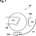
Bei den Rohdrehwinkelsignalen s_r, c_r handelt es sich um ein periodisches Signal, beispielsweise ein Sinus- und ein Kosinus-Signal, die um 90° zueinander Phasen verschoben sind. Aufgrund der Orthogonalen Beziehung zwischen den Sensorsignalen sollten die Sensorsignale die Bedingung gemäß dem Additionstheorem sin2(x) + cos2(x) = 1 einhalten, mit x als Wert des Drehwinkels. Aufgrund unterschiedlicher Ursachen, die bspw. einmalig in der Produktion des Winkelsensors
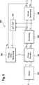
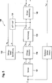
In
Das Verfahren wird in der Weise durchgeführt, dass zum einen die Ermittlungseinheit
Des weiteren weist das Ausführungsbeispiel die Eigenschaft auf, dass die korrigierten und normierten Rohdrehwinkelsignale s_n, c_n laufend zum Ermitteln des Korrekturwertes abgerufen werden. Hierzu werden, wie in
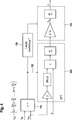
Die Ermittlungseinheit
Innerhalb des DFT-Blocks 

Jedoch wird das nur für bestimmte Winkelpositionen bzw. Winkel durchgeführt. Dazu wird der aktuelle korrigierte Drehwinkel x_tl abgerufen und eine Überprüfung
Ist dies der Fall, wird die Berechnung des Summanden e ^_2,im durchgeführt, was durch den Pfeil
Aus dem imaginären Anteil der zweiten Oberwelle e ^_2,im kann dann mittels der Gleichung ein Einzelkorrekturwert
Für die Kompensation des Orthogonalitätsfehlers muss der Wert y aus der Summe
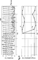
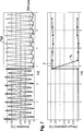
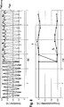
Die Rohdrehwinkel x wurden an realen Resolvern mit anschließender Simulation des Winkelfehlers vorgenommen, d. h. der Winkelfehler wurde künstlich hinzugefügt. Die Signale x_ref, x_tl, s_r und c_r wurden aufgezeichnet. Es wurden unterschiedliche Orthogonalitätsfehler verwendet, wie nachfolgend beschrieben.The raw angles of rotation x were made on real resolvers with subsequent simulation of the angle error, d. H. the angle error was added artificially. The signals x_ref, x_tl, s_r and c_r were recorded. Different orthogonality errors were used, as described below.
Während der Simulation werden die Signale s_r und c_r als Stimuli in das Model geführt. Damit sind zwei Systeme zur Winkelberechnung realisiert, die exakt die gleichen Eingangsdaten erhalten. Zum einen die Modelsimulation mit automatischer Orthogonalitätskompensation mittels des Korrekturwertes y. Darüber hinaus wurde noch ein Steuergerät ohne Orthogonalitätskompensation zum Vergleich herangezogen.During the simulation, the s_r and c_r signals are fed into the model as stimuli. Thus, two systems for angle calculation are realized, which receive exactly the same input data. On the one hand, the model simulation with automatic orthogonality compensation by means of the correction value y. In addition, a control unit without orthogonality compensation was used for comparison.
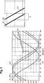
Der vom Model errechnete Winkel x_tl kann mit dem Referenzwinkel x_ref verglichen werden und bildet die Winkeldifferenz x_diff, comp. Daneben wird der Winkelfehler ohne Orthogonalitätskomensation aus den gemessenen Werten des Steuergerätes als x_diff zum Vergleich berechnet. Beiden Systemen werden etwa 3,2 s Zeit zum Einschwingen geben, bevor die Simulation die automatische Orthogonalitätskorrektur durchführt. Damit kann die Wirkung visuell gut dargestellt werden.The angle x_tl calculated by the model can be compared with the reference angle x_ref and forms the angle difference x_diff, comp. In addition, the angle error without orthogonality compensation is calculated from the measured values of the control unit as x_diff for comparison. Both systems will settle for about 3.2 seconds before the simulation performs automatic orthogonality correction. Thus, the effect can be visualized visually.
Die
- –
6 : 0,154° el - –
7 : 0,655° el - –
8 : –0,3° el.
- -
6 : 0.154 ° el - -
7 : 0.655 ° el - -
8th : -0.3 ° el.
Im oberen Diagramm ist jeweils der Winkelfehler ohne Kompensation x_diff als rote/gestrichelte Linie dargestellt. Der kompensierte Wert x_diff_comp ist als blaue/durchgezogene Linie. Zum Zeitpunkt t = 3,75 s wurde der erste Wert für den Orthogonalitätsfehler bestimmt und der Orthogonalitätskompensation zugeführt. Die Wirkung ist deutlich zu sehen, der Winkelfehler besitzt keine dominante 2. Ordnung mehr.The upper diagram shows the angle error without compensation x_diff as a red / dashed line. The compensated value x_diff_comp is shown as a blue / solid line. At the time t = 3.75 s, the first value for the orthogonality error was determined and fed to the orthogonality compensation. The effect is clear to see, the angle error has no dominant 2nd order more.
Im unteren Diagramm sind als grüne/durchgezogene Linie das Signal y als der ermittelte Orthogonalitätsfehler und als blaue/gestrichelte Linie das Signal y_s als der ermittelten_ Rest-Orthogonalitätsfehler dargestellt.In the lower diagram, the signal y as the determined orthogonality error is shown as a green / solid line, and the signal y_s as a blue / dashed line as the determined_ residual orthogonality error.
In den
Der Kompensationswert y wurde ohne Glättung direkt angewendet, wodurch besonders in
Zu beachten ist, dass der Kompensationswert der Spitze-Spitze-Wert des harmonischen Winkelfehlers ist. Er hat damit den 2-fachen Wert des y_s = arcsin (e_2,im). Weiterhin ist gut zu erkennen, dass die Korrektur des Orthogonalitätsfehlers die Winkelverschiebung in Höhe des Orthogonalitätsfehlers beseitigt.Note that the compensation value is the peak-to-peak value of the harmonic angle error. It has twice the value of y_s = arcsin (e_2, im). Furthermore, it can be clearly seen that the correction of the orthogonality error eliminates the angular displacement in the amount of orthogonality error.
Nachfolgend sind weitere vorteilhafte Varianten aufgelistet, die mit den vorgenannten Ausführungsformen kombinierbar sind:
- 1. Verfahren zum Ermitteln eines Fehlers (y) zwischen zwei Sensorsignalen (s1, s2) in einem Winkelsensor, der in Abhängigkeit eines Winkelgebers die Sensorsignale (s1, s2) ausgibt, die einen periodischen Verlauf aufweisen und mathematisch in einem orthogonalen Verhältnis zueinander stehen, wobei aufgrund des Fehlers (y) eine Abweichung vom orthogonalen Verhältnis zwischen den Sensorsignalen auftreten kann, aufweisend die Schritte:
- – Bilden eines Radiussignals (e_orth) mittels der Quadratsummen der Sensorsignale,
- –
Ermitteln der 2·n-ten Oberwelle des Radiussignals (e_orth), mit n gleich einer ganzen positiven Zahl, und - – Ermitteln des Fehlers eines um 90° zum Drehwinkelwert phasenverschobenen Wert der Amplitude an der zweiten Oberwelle.
- 2.
Verfahren nach Anspruch 1, gekennzeichnet durch - – Ermitteln eines Frequenzanteils oder -anteile der Radiussignals mittels einer Fourier Transformation, und
- – Ermitteln des Fehlers anhand des imaginären Anteils des Frequenzanteils oder der Frequenzanteile der zweiten Oberwelle.
- 3.
Verfahren nach Anspruch 2, dadurch gekennzeichnet, dass die Fourier Transformation mittels einer schnellen und/oder diskreten Fourier Transformation durchgeführt wird. - 4.
Verfahren nach Anspruch 2oder 3, gekennzeichnet durch, Berechnen des Fehlers y mittels der Gleichungy = arcsin|e_orth, 2·n.,im| - 5. Verfahren nach einem der vorstehenden Ansprüche, dadurch gekennzeichnet, dass der
reale Anteil der 2·n-ten Oberwelle als Maßstab für einen Skalierungsfehler verwendet wird. - 6. Verfahren nach einem der vorstehenden Ansprüche, dadurch gekennzeichnet, dass das Verfahren im laufenden Betrieb verwendet wird.
- 7. Verfahren nach einem der Ansprüche 1–5, dadurch gekennzeichnet, dass das Verfahren vor Inbetriebnahme eines Winkelsensors durchgeführt wird, insbesondere mittels einer externen Recheneinheit.
- 8. Verfahren zum Ermitteln eines Fehlers (y) zwischen zwei Sensorsignalen (s1, s2) in einem Winkelsensor, der in Abhängigkeit eines Winkelgebers die Sensorsignale (s1, s2) ausgibt, die einen periodischen Verlauf aufweisen und mathematisch in einem orthogonalen Verhältnis zueinander stehen, wobei aufgrund des Fehlers (y) eine Abweichung vom orthogonalen Verhältnis zwischen den Sensorsignalen auftreten kann, aufweisend die Schritte:
- – Ermitteln eines Drehwinkels (x) aus den Sensorsignalen (s1, s2),
- – Ermitteln eines Umwandlungswertes durch Ausführen einer Fourier Transformation für den ermittelten Drehwinkel,
- – Ermitteln des Fehlers anhand des Umwandlungswertes.
- 9. Winkelsensor zum Erfassen eines Drehwinkels, umfassend
- – ein Sensorelement, das in Abhängigkeit eines Winkelgebers die Sensorsignale ausgibt, die einen periodischen Verlauf aufweisen und mathematisch in einem orthogonalen Verhältnis zueinander stehen, und
- – eine Recheneinheit zum durchführen des Verfahrens nach einem der vorstehenden Ansprüche.
- 1. A method for determining an error (y) between two sensor signals (s1, s2) in an angle sensor which outputs the sensor signals (s1, s2) in dependence on an angle sensor, which have a periodic course and are mathematically in an orthogonal relationship to each other, wherein, due to the error (y), a deviation from the orthogonal relationship between the sensor signals may occur, comprising the steps of:
- Forming a radius signal (e_orth) by means of the sums of squares of the sensor signals,
- - Determining the 2 nth harmonic of the radius signal (e_orth), with n equal to a whole positive number, and
- - Determining the error of a phase-shifted by 90 ° to the angle of rotation value of the amplitude at the second harmonic.
- 2. The method according to
claim 1, characterized by - Determining a frequency component or portions of the radius signal by means of a Fourier transformation, and
- - Determine the error based on the imaginary part of the frequency component or the frequency components of the second harmonic.
- 3. The method according to
claim 2, characterized in that the Fourier transformation is performed by means of a fast and / or discrete Fourier transformation. - 4. The method of
claim y = arcsin | e_orth, 2 · n., in | - 5. The method according to any one of the preceding claims, characterized in that the real part of the 2 nth harmonic wave is used as a scale for a scaling error.
- 6. The method according to any one of the preceding claims, characterized in that the method is used during operation.
- 7. The method according to any one of claims 1-5, characterized in that the method is carried out before commissioning of an angle sensor, in particular by means of an external computing unit.
- 8. A method for determining an error (y) between two sensor signals (s1, s2) in an angle sensor which outputs the sensor signals (s1, s2) in dependence on an angle sensor, which have a periodic course and are mathematically in an orthogonal relationship to each other, wherein, due to the error (y), a deviation from the orthogonal relationship between the sensor signals may occur, comprising the steps of:
- Determining a rotation angle (x) from the sensor signals (s1, s2),
- Determining a conversion value by performing a Fourier transformation for the determined rotation angle,
- - Determine the error based on the conversion value.
- 9. An angle sensor for detecting a rotation angle, comprising
- A sensor element that outputs the sensor signals as a function of an angle sensor, which have a periodic course and are mathematically in an orthogonal relationship to one another, and
- - A computing unit for carrying out the method according to any one of the preceding claims.
ZITATE ENTHALTEN IN DER BESCHREIBUNG QUOTES INCLUDE IN THE DESCRIPTION
Diese Liste der vom Anmelder aufgeführten Dokumente wurde automatisiert erzeugt und ist ausschließlich zur besseren Information des Lesers aufgenommen. Die Liste ist nicht Bestandteil der deutschen Patent- bzw. Gebrauchsmusteranmeldung. Das DPMA übernimmt keinerlei Haftung für etwaige Fehler oder Auslassungen.This list of the documents listed by the applicant has been generated automatically and is included solely for the better information of the reader. The list is not part of the German patent or utility model application. The DPMA assumes no liability for any errors or omissions.
Zitierte PatentliteraturCited patent literature
- DE 102010003201 A1 [0002] DE 102010003201 A1 [0002]
- DE 102014216224 [0003] DE 102014216224 [0003]
Claims (14)
Priority Applications (1)
| Application Number | Priority Date | Filing Date | Title |
|---|---|---|---|
| DE102015215510.2A DE102015215510A1 (en) | 2014-08-14 | 2015-08-13 | Method for determining an orthogonality error between two sensor signals |
Applications Claiming Priority (5)
| Application Number | Priority Date | Filing Date | Title |
|---|---|---|---|
| DE102014216224 | 2014-08-14 | ||
| DE102014216224.6 | 2014-08-14 | ||
| DE102014220331.7 | 2014-10-07 | ||
| DE102014220331 | 2014-10-07 | ||
| DE102015215510.2A DE102015215510A1 (en) | 2014-08-14 | 2015-08-13 | Method for determining an orthogonality error between two sensor signals |
Publications (1)
| Publication Number | Publication Date |
|---|---|
| DE102015215510A1 true DE102015215510A1 (en) | 2016-02-18 |
Family
ID=53836097
Family Applications (1)
| Application Number | Title | Priority Date | Filing Date |
|---|---|---|---|
| DE102015215510.2A Withdrawn DE102015215510A1 (en) | 2014-08-14 | 2015-08-13 | Method for determining an orthogonality error between two sensor signals |
Country Status (6)
| Country | Link |
|---|---|
| US (1) | US20170153127A1 (en) |
| EP (1) | EP3180592A1 (en) |
| KR (1) | KR20170029608A (en) |
| CN (1) | CN106574851A (en) |
| DE (1) | DE102015215510A1 (en) |
| WO (1) | WO2016024001A1 (en) |
Cited By (2)
| Publication number | Priority date | Publication date | Assignee | Title |
|---|---|---|---|---|
| EP3916361A4 (en) * | 2019-01-22 | 2022-01-19 | Mitsubishi Electric Corporation | Rotation angle detection device, and electric power steering device including same rotation angle detection device |
| WO2022057963A1 (en) * | 2020-09-18 | 2022-03-24 | Schaeffler Technologies AG & Co. KG | Method for detecting an angular position, and detection system |
Families Citing this family (2)
| Publication number | Priority date | Publication date | Assignee | Title |
|---|---|---|---|---|
| US11680005B2 (en) * | 2020-02-12 | 2023-06-20 | Owens-Brockway Glass Container Inc. | Feed material for producing flint glass using submerged combustion melting |
| DE102020102065B3 (en) * | 2020-01-29 | 2021-06-02 | Schaeffler Technologies AG & Co. KG | Clutch actuator, detection system and method for detecting an angular position of a rotating component |
Citations (3)
| Publication number | Priority date | Publication date | Assignee | Title |
|---|---|---|---|---|
| DE10163504A1 (en) * | 2001-12-21 | 2003-07-10 | Siemens Ag | Method for iterative error compensation of a sine-cosine position measurement system for application to offset, amplitude and phase errors, so that almost exact correction values can be determined |
| DE102004038621B3 (en) * | 2004-08-09 | 2006-02-16 | Siemens Ag | Determination procedure for a position signal |
| DE102010003201A1 (en) | 2009-05-08 | 2010-12-23 | Continental Teves Ag & Co. Ohg | Angle-measuring method for determining an angle of tilt/swiveling angle uses an angle-measuring unit and first and second measuring signals |
Family Cites Families (8)
| Publication number | Priority date | Publication date | Assignee | Title |
|---|---|---|---|---|
| US5463393A (en) * | 1991-12-05 | 1995-10-31 | Acutronic Ag | Method and apparatus for correcting errors in an amplitude encoded signal |
| WO2005050140A1 (en) * | 2003-11-18 | 2005-06-02 | Koninklijke Philips Electronics N.V. | Position determining |
| JP4713123B2 (en) * | 2004-10-13 | 2011-06-29 | 株式会社ミツトヨ | Encoder output signal correction device |
| EP1804032A1 (en) * | 2004-10-20 | 2007-07-04 | Kabushiki Kaisha Yaskawa Denki | Encoder signal processor and processing method |
| JP4568298B2 (en) * | 2007-03-16 | 2010-10-27 | オークマ株式会社 | Position detection device |
| JP5178374B2 (en) * | 2008-07-29 | 2013-04-10 | キヤノン株式会社 | Detection device |
| JP2010156554A (en) * | 2008-12-26 | 2010-07-15 | Okuma Corp | Position detecting apparatus |
| JP5836026B2 (en) * | 2011-09-08 | 2015-12-24 | 三菱重工業株式会社 | Error frequency component acquisition device, rotation angle acquisition device, and motor control device |
-
2015
- 2015-08-13 CN CN201580043308.7A patent/CN106574851A/en active Pending
- 2015-08-13 WO PCT/EP2015/068711 patent/WO2016024001A1/en active Application Filing
- 2015-08-13 EP EP15750060.4A patent/EP3180592A1/en not_active Withdrawn
- 2015-08-13 DE DE102015215510.2A patent/DE102015215510A1/en not_active Withdrawn
- 2015-08-13 KR KR1020177003996A patent/KR20170029608A/en not_active Application Discontinuation
-
2017
- 2017-02-14 US US15/432,580 patent/US20170153127A1/en not_active Abandoned
Patent Citations (3)
| Publication number | Priority date | Publication date | Assignee | Title |
|---|---|---|---|---|
| DE10163504A1 (en) * | 2001-12-21 | 2003-07-10 | Siemens Ag | Method for iterative error compensation of a sine-cosine position measurement system for application to offset, amplitude and phase errors, so that almost exact correction values can be determined |
| DE102004038621B3 (en) * | 2004-08-09 | 2006-02-16 | Siemens Ag | Determination procedure for a position signal |
| DE102010003201A1 (en) | 2009-05-08 | 2010-12-23 | Continental Teves Ag & Co. Ohg | Angle-measuring method for determining an angle of tilt/swiveling angle uses an angle-measuring unit and first and second measuring signals |
Cited By (2)
| Publication number | Priority date | Publication date | Assignee | Title |
|---|---|---|---|---|
| EP3916361A4 (en) * | 2019-01-22 | 2022-01-19 | Mitsubishi Electric Corporation | Rotation angle detection device, and electric power steering device including same rotation angle detection device |
| WO2022057963A1 (en) * | 2020-09-18 | 2022-03-24 | Schaeffler Technologies AG & Co. KG | Method for detecting an angular position, and detection system |
Also Published As
| Publication number | Publication date |
|---|---|
| EP3180592A1 (en) | 2017-06-21 |
| CN106574851A (en) | 2017-04-19 |
| KR20170029608A (en) | 2017-03-15 |
| US20170153127A1 (en) | 2017-06-01 |
| WO2016024001A1 (en) | 2016-02-18 |
Similar Documents
| Publication | Publication Date | Title |
|---|---|---|
| DE102015202436B4 (en) | Apparatus, method and non-transitory computer-readable medium for compensating a position information error of a resolver | |
| DE102015215510A1 (en) | Method for determining an orthogonality error between two sensor signals | |
| DE102011055000A1 (en) | A rotation angle detecting device and an electric power steering device using the same | |
| DE102016112670A1 (en) | Correction device and method for an angle sensor, and angle sensor | |
| DE102017127799A1 (en) | FAULT TOLERANT MEASUREMENT OF PHASE FLOWS FOR MOTOR CONTROL SYSTEMS | |
| DE112018004187T5 (en) | Systems and methods for correcting non-sinusoidal signals generated by non-circular couplers | |
| DE102015218855A1 (en) | Signal transmitter with improved detection of the angle signal | |
| DE102017111979A1 (en) | Angle sensor, correction method for use with the angle sensor and angle sensor system | |
| DE102014210009A1 (en) | Signal processing method using variable coefficients | |
| DE102013206264A1 (en) | Method and apparatus for performing a calculation of a data-based function model | |
| EP2211148A2 (en) | Method and device for determining an angular position by means of a resolver | |
| DE102009051624A1 (en) | Method for analyzing spectral portion of rotational speed-signal of crankshaft of internal-combustion engine, involves calculating discrete Fourier transform for number of scanning values, and determining spectral portion of signal | |
| DE102011089820A1 (en) | Method for determining the absolute position of a linear actuator | |
| EP3615893B1 (en) | Determining a rotational angle of a steering shaft by means of three gear wheels | |
| DE112018005113T5 (en) | METHOD FOR ESTIMATING A FRICTION VALUE | |
| DE102004029815A1 (en) | Method and arrangement for correcting an angle and / or distance measuring sensor system | |
| DE102014226604B4 (en) | Method and device for compensating for an arrangement tolerance between two sensor elements of a position sensor arrangement | |
| DE102015001147A1 (en) | Motor control device for correcting an interpolation error of a position detection device | |
| EP1901421A1 (en) | Method for determining rotor position of a rotating electrical machine | |
| DE102015110460A1 (en) | Detection of a mains phase failure in converters with frequency detection in the DC link voltage | |
| DE102021206006A1 (en) | Electrical machine with a stator and a rotor, in particular designed to be permanent magnets, having at least a first subsystem and a second subsystem, each with a plurality of phases for driving the electrical machine | |
| DE10247321B3 (en) | Sensing rotary motion and torque from phase measurements and computerized linear transformation, adopts iterative approximation technique | |
| DE102015215511A1 (en) | Method for determining an orthogonality error between two sensor signals | |
| DE102015117719B4 (en) | Method for operating a steering system of a motor vehicle | |
| DE112018006842T5 (en) | Control device for a rotary machine |
Legal Events
| Date | Code | Title | Description |
|---|---|---|---|
| R163 | Identified publications notified | ||
| R119 | Application deemed withdrawn, or ip right lapsed, due to non-payment of renewal fee |