DE102015114751A1 - SAW filter - Google Patents
SAW filter Download PDFInfo
- Publication number
- DE102015114751A1 DE102015114751A1 DE102015114751.3A DE102015114751A DE102015114751A1 DE 102015114751 A1 DE102015114751 A1 DE 102015114751A1 DE 102015114751 A DE102015114751 A DE 102015114751A DE 102015114751 A1 DE102015114751 A1 DE 102015114751A1
- Authority
- DE
- Germany
- Prior art keywords
- parallel
- resonators
- band
- filter
- series
- Prior art date
- Legal status (The legal status is an assumption and is not a legal conclusion. Google has not performed a legal analysis and makes no representation as to the accuracy of the status listed.)
- Withdrawn
Links
Images


Classifications
-
- H—ELECTRICITY
- H03—ELECTRONIC CIRCUITRY
- H03H—IMPEDANCE NETWORKS, e.g. RESONANT CIRCUITS; RESONATORS
- H03H9/00—Networks comprising electromechanical or electro-acoustic devices; Electromechanical resonators
- H03H9/46—Filters
- H03H9/64—Filters using surface acoustic waves
- H03H9/6423—Means for obtaining a particular transfer characteristic
- H03H9/6433—Coupled resonator filters
- H03H9/6483—Ladder SAW filters
-
- H—ELECTRICITY
- H03—ELECTRONIC CIRCUITRY
- H03H—IMPEDANCE NETWORKS, e.g. RESONANT CIRCUITS; RESONATORS
- H03H9/00—Networks comprising electromechanical or electro-acoustic devices; Electromechanical resonators
- H03H9/02—Details
- H03H9/02535—Details of surface acoustic wave devices
- H03H9/02818—Means for compensation or elimination of undesirable effects
- H03H9/02866—Means for compensation or elimination of undesirable effects of bulk wave excitation and reflections
-
- H—ELECTRICITY
- H03—ELECTRONIC CIRCUITRY
- H03H—IMPEDANCE NETWORKS, e.g. RESONANT CIRCUITS; RESONATORS
- H03H9/00—Networks comprising electromechanical or electro-acoustic devices; Electromechanical resonators
- H03H9/02—Details
- H03H9/02535—Details of surface acoustic wave devices
- H03H9/02543—Characteristics of substrate, e.g. cutting angles
- H03H9/02559—Characteristics of substrate, e.g. cutting angles of lithium niobate or lithium-tantalate substrates
-
- H—ELECTRICITY
- H03—ELECTRONIC CIRCUITRY
- H03H—IMPEDANCE NETWORKS, e.g. RESONANT CIRCUITS; RESONATORS
- H03H9/00—Networks comprising electromechanical or electro-acoustic devices; Electromechanical resonators
- H03H9/02—Details
- H03H9/02535—Details of surface acoustic wave devices
- H03H9/02818—Means for compensation or elimination of undesirable effects
- H03H9/02834—Means for compensation or elimination of undesirable effects of temperature influence
Abstract
Zur Vermeidung einer störenden Resonanz im Gegenband eines SAW Filters mit Ladder Type Struktur wird vorgeschlagen, die Fingerperiode der Parallelresonatoren zu verringern und im Gegenzug die Parallelarme mit einer entsprechenden Induktivität zu verschalten, um die Bandbreite wieder auf den ursprünglichen Wert zu erweitern. Mit der Verschiebung der Hauptresonanz gelingt es gleichzeitig, die Frequenz der Nebenmode aus dem Bereioch des Gegenbands heraus zu verschieben.To avoid a disturbing resonance in the opposite band of a SAW filter ladder type structure is proposed to reduce the finger period of the parallel resonators and in turn connect the parallel arms with a corresponding inductance to expand the bandwidth back to its original value. At the same time, with the shift of the main resonance, it is possible to shift the frequency of the secondary mode out of the Bereioch of the opposite band.
Description
Zur Verminderung des Temperaturgangs von SAW-Filtern werden diese mit einer üblicherweise SiO2 umfassenden Kompensationsschicht versehen. To reduce the temperature coefficient of SAW filters, they are provided with a compensation layer which usually comprises SiO 2 .
Aus SAW-Resonatoren aufgebaute Bandpassfilter mit einer Kompensationsschicht können beispielsweise auf Lithiumniobat-Kristallen mit einem Schnittwinkel rot-128 aufgebaut werden. Auf diesem Substratmaterial wird die Resonanzfrequenz der akustischen Rayleigh-Mode genutzt. Bandpass filters with a compensation layer constructed from SAW resonators can be constructed, for example, on lithium niobate crystals with a red-128 cutting angle. On this substrate material, the resonance frequency of the acoustic Rayleigh mode is used.
Der Schichtaufbau solcher SAW Filter hat jedoch zur Folge, dass neben der sich horizontal ausbreitenden Rayleigh Welle als Nebenmode noch eine sich vertikal zur Schichtebene ausbreitende Platten-Mode auftritt, deren Frequenz oberhalb der Frequenz der Rayleigh Welle liegt und bei einem gegebenen Schichtaufbau einen festen Abstand dazu aufweist.However, the layer structure of such SAW filters has the consequence that in addition to the horizontally propagating Rayleigh wave as a secondary mode still a vertically extending to the layer plane plate mode occurs whose frequency is above the frequency of the Rayleigh wave and at a given layer structure at a fixed distance having.
Liegt nun die Frequenz der Platten-Mode in einem Frequenzband, welches zum Beispiel ein Gegenband für eine Bandkombination im Carrier Aggregation Betrieb ist, das für diese Anwendung zu unterdrücken ist, so stört die Platten-Mode und kann dazu führen, dass wegen der unzulässig schlechten Unterdrückung die Spezifikationen für diese Anwendung nicht erfüllt werden können.If the frequency of the disk mode now lies in a frequency band which, for example, is a counterpart band for a band combination in carrier aggregation operation, which is to be suppressed for this application, then the disk mode interferes and can lead to unacceptably bad performance Suppression the specifications for this application can not be met.
Aufgabe der vorliegenden Erfindung ist es daher, eine störende Platten-Mode, die im Frequenzbereich eines zu unterdrückenden Gegenbandes oberhalb des Passbands auftritt, unschädlich zu machen. The object of the present invention is therefore to render harmless a disturbing plate mode, which occurs in the frequency range of a counter-band to be suppressed above the passband.
Diese Aufgabe wird erfindungsgemäß durch ein SAW-Filter nach Anspruch 1 gelöst. Vorteilhafte Ausgestaltungen der Erfindung gehen aus weiteren Ansprüchen hervor.This object is achieved by a SAW filter according to
Es wird ein SAW-Filter angegeben, welches eine herkömmliche Ladder-Type-Struktur aufweist. Diese umfasst einen zwischen Filterein- und -ausgang verschalteten Serienzweig, in dem Serienresonatoren angeordnet sind. Von diesem Serienzweig zweigen n parallel zueinander gegen ein Festpotenzial verschaltete Parallelzweige ab, in denen jeweils ein Parallelresonator angeordnet ist. Es sind zumindest zwei Parallelzweige (n ≥ 2) vorgesehen. Zur Verbesserung der Selektion des Filters kann die Anzahl n der Parallelzweige auf beispielsweise fünf erhöht werden. Die Serienresonatoren und die Parallelresonatoren spannen zusammen ein Passband auf. There is provided a SAW filter having a conventional ladder-type structure. This comprises a series branch connected between the filter inlet and outlet, in which series resonators are arranged. From this series branch branch parallel branches parallel to each other against a fixed potential, in each of which a parallel resonator is arranged. At least two parallel branches (n ≥ 2) are provided. To improve the selection of the filter, the number n of parallel branches can be increased to, for example, five. The series resonators and the parallel resonators span a pass band together.
Abweichend von einem herkömmlichen Design, das auf die genaue Ausformung des Passbands ausgelegt ist, weist im erfindungsgemäßen SAW-Filter ein erster Parallelresonator eine Fingerperiode p auf, die geringer ist, als eine Designoptimierung eigentlich vorschreiben würde und als es für die Gestaltung des Passbands erforderlich wäre. Dementsprechend erscheint die Hauptresonanz des ersten Parallelresonators bei einer höheren Frequenz und liegt damit näher an der linken Passbandkante als optimal. Die durch diese Maßnahme beeinträchtigte Bandbreite des Passbands ist im erfindungsgemäßen SAW-Filter durch eine Parallelinduktivität kompensiert, die im ersten Parallelzweig (d.h. im Parallelzweig mit dem ersten Parallelresonator) angeordnet ist und in Serie zum Parallelresonator geschaltet ist.Unlike a conventional design, which is designed for the exact shape of the passband, in the SAW filter according to the invention, a first parallel resonator has a finger period p, which is lower than a design optimization would actually prescribe and as would be required for the design of the passport , Accordingly, the main resonance of the first parallel resonator appears at a higher frequency and is thus closer to the left passband edge than optimal. The bandwidth of the passband affected by this measure is compensated in the inventive SAW filter by a parallel inductance which is arranged in the first parallel branch (i.e., in parallel with the first parallel resonator) and connected in series with the parallel resonator.
Mit der Frequenzverschiebung der Hauptresonanz zumindest des ersten Parallelresonators wird auch die Frequenz einer störenden Nebenmode verschoben. So wird erreicht, dass dadurch auch die Nebenmode aus einem zu unterdrückenden Nebenband des Filters heraus verschoben ist.The frequency shift of the main resonance of at least the first parallel resonator also shifts the frequency of a disturbing secondary mode. Thus it is achieved that thereby also the secondary mode is shifted out of a side band of the filter to be suppressed.
Die Erfindung ist vorteilhaft anwendbar insbesondere für Resonatoren mit einem Schichtaufbau, bei dem als Nebenmode eine Platten-Mode auftritt, die auch Z-harmonische Mode genannt wird und in fester Entfernung zur Hauptresonanz auftritt. Diese Platten-Mode ist oberhalb des Passbands angesiedelt. The invention is advantageously applicable in particular to resonators with a layer structure in which a plate mode, which is also called Z-harmonic mode and occurs at a fixed distance from the main resonance, occurs as a secondary mode. This plate fashion is located above the passband.
Mit der Erfindung wird ein SAW-Filter erhalten, das genau wie ein auf herkömmlichem Weg optimiertes SAW-Filter ein gut angepasstes Passband entsprechend den geforderten Spezifikationen aufweist bzw. dessen Passband diesen Spezifikationen entspricht. Flankensteilheit und Passbandbreite sind nahezu unverändert gegenüber dem herkömmlichen Design. Die störende Nebenmode, insbesondere die störende Platten-Mode ist nun aus dem Gegenband heraus verschoben, so dass das Filter im Frequenzbereich des Gegenbands eine verbesserte Dämpfung aufweist. With the invention, a SAW filter is obtained which, just like a SAW filter optimized in a conventional way, has a well-adapted pass band corresponding to the required specifications or whose pass band corresponds to these specifications. Slope and passband width are almost unchanged compared to the conventional design. The disturbing secondary mode, in particular the disturbing plate mode is now shifted out of the opposite band, so that the filter has an improved attenuation in the frequency range of the opposite band.
Die Parallelinduktivität wird vorzugsweise mit hoher Güte ausgebildet und beispielsweise als Kupferspule realisiert. Ist das SAW-Filter in Flip-Chip-Bauweise auf einem Träger aufgebracht, so kann die Parallelinduktivität in Form der Kupferspule zwischen dem Träger und dem Chip auf dem Träger angeordnet werden. Möglich ist es jedoch auch, das SAW-Filter mit einer als diskretes Bauelement ausgebildeter Parallelinduktivität zu verschalten. The parallel inductance is preferably formed with high quality and implemented, for example, as a copper coil. If the SAW filter is applied in a flip-chip design on a carrier, then the parallel inductance in the form of the copper coil between the carrier and the chip can be arranged on the carrier. However, it is also possible to connect the SAW filter with a trained as a discrete component parallel inductance.
Die Frequenzen der Hauptresonanzen der Parallelresonatoren können bei herkömmlichem Design unterschiedliche Werte aufweisen. Wenn nun die Lage einer solchen weiteren Hauptresonanz eines Parallelresonators ebenfalls so liegt, dass auch die Frequenz einer davon abhängigen Nebenmode im zu unterdrückenden Gegenband liegt, so wird gemäß einer Ausführungsform der Erfindung die Hauptresonanz auch dieses Parallelresonators und damit verbunden gleichzeitig auch die Nebenmode hin zu höheren Frequenzen verschoben, sodass auch die Resonanz der Nebenmode außerhalb des zu unterdrückenden Gegenbands liegt. In allen Parallelzweigen, in denen der dazugehörige Parallelresonator mit einer höheren Resonanzfrequenz ausgestattet ist, werden Parallelinduktivitäten in Serie zum Parallelresonator geschaltet. The frequencies of the main resonances of the parallel resonators may have different values in conventional design. If the position of such a further main resonance of a parallel resonator is also such that the frequency of a dependent secondary mode is also to be suppressed in the counterpart band, according to one embodiment of the invention the main resonance will also be that parallel resonator and at the same time also the secondary mode towards higher Shifted frequencies, so that the Resonance of the secondary mode is outside of the suppressed band to be suppressed. In all parallel branches, in which the associated parallel resonator is equipped with a higher resonance frequency, parallel inductors are connected in series with the parallel resonator.
Ein erfindungsgemäßes SAW-Filter, das eine ausgeprägte Nebenmode aufweist, ist beispielsweise auf einem Lithium-Niobat-Substrat realisiert, welches einen Schnittwinkel zwischen rot 125 und rot 130 aufweist. Derartige Filter können darüber hinaus über ihrer Elektrodenmetallisierung noch eine SiO2-Schicht aufweisen, die zur Kompensation des Temperaturkoeffizienten der Frequenz (TCF) genutzt wird. Weiter kann ein solches Filter noch eine Trimmschicht aufweisen, die zur individuellen Frequenzabstimmung der Resonatoren benötigt wird, um die höhere Toleranz bei der Herstellung des genannten Schichtaufbaus zu kompensieren. An inventive SAW filter, which has a pronounced secondary mode, is realized, for example, on a lithium niobate substrate which has a cutting angle between red 125 and red 130. In addition, such filters can also have an SiO 2 layer over their electrode metallization, which is used to compensate for the temperature coefficient of the frequency (TCF). Furthermore, such a filter may also have a trim layer, which is required for the individual frequency tuning of the resonators in order to compensate for the higher tolerance in the production of said layer structure.
Ein SAW-Filter mit einer solchen TCF-Kompensationsschicht und gegebenenfalls einer Trimmschicht weist in der Regel die ausgeprägte Platten-Mode auf. Für bestimmte Anwendungen liegt diese Platten-Mode gerade in einem zu unterdrückenden Gegenband.A SAW filter with such a TCF compensation layer and optionally a trim layer usually has the pronounced plate mode. For certain applications, this disk mode is currently in a contraband to be suppressed.
Vorteilhaft wird die Erfindung bei einem TX-Filter eingesetzt, dessen Spezifikationen eine höhere Unterdrückung der Gegenbänder erfordern, als dies bei einem RX-Filter der Fall ist. Ein solches TX-Filter, bei dem die Erfindung verwirklicht ist, kann Teil eines Duplexers sein. Der Duplexer kann parallel zu bzw. zusammen mit einem weiteren Duplexer mit einem gemeinsamen Antennenanschluss verbunden sein. Im so genannten Carrier Aggregation Mode können dann zwei Duplexer parallel zur gleichen Zeit betrieben werden, um zumindest in einer Richtung (upstream oder downstream) zwei unterschiedliche Bänder für eine einzige Kommunikationsverbindung oder Datenübertragung zu nutzen. Dies erhöht die Bandbreite bei der Datenübertragung. Advantageously, the invention is used in a TX filter whose specifications require a higher suppression of the counterbands, as is the case with an RX filter. Such a TX filter embodying the invention may be part of a duplexer. The duplexer may be connected in parallel with or together with another duplexer to a common antenna port. In the so-called carrier aggregation mode, two duplexers can then be operated in parallel at the same time in order to use two different bands for a single communication connection or data transmission at least in one direction (upstream or downstream). This increases the bandwidth during data transmission.
Beinhaltet der Carrier Aggregation Mode eine Bandkombination, bei der zwei der Bänder genau den Abstand zueinander aufweist, der der Entfernung der Platten-Mode von der Hauptresonanz eines in einem Filter eingesetzten Resonators entspricht, so kann die Erfindung vorteilhaft für solche Anwendungsfälle eingesetzt werden.If the carrier aggregation mode includes a band combination in which two of the bands have exactly the distance to one another which corresponds to the removal of the plate mode from the main resonance of a resonator inserted in a filter, then the invention can advantageously be used for such applications.
Gemäß einer weiteren Ausgestaltung der Erfindung und insbesondere in Verbindung mit der Verschiebung der Platten-Mode wird vorgesehen, sowohl das TX-Filter als auch das RX-Filter eines Duplexers erfindungsgemäß auszubilden. Die Serienzweige der beiden Filter werden dann mit einem gemeinsamen Antennenanschluss verbunden. Vorteilhaft ist es nun, die Serienzweige über einen endständigen Serienresonator an den gemeinsamen Antennenanschluss anzuschließen. Dies bedeutet, dass der jeweilige endständige Serienresonator zwischen dem Antennenanschluss und dem jeweiligen ersten Schaltungsknoten, von dem der erste Parallelzweig abzweigt, angeordnet ist. In einer vorteilhaften Ausgestaltung der Erfindung wird eine weitere Verbesserung dadurch erzielt, dass die statische Kapazität CSRS1 dieses ersten Serienresonators, also des Serienresonators, der dem Antennenanschluss am Nächsten gelegen ist, minimal ausgebildet ist. Die statische Kapazität kann durch eine geringere Apertur, durch eine verringerte Anzahl von Fingern und/oder durch eine Kaskadierung von Resonatoren erreicht werden. Die Kaskadierung von Resonatoren hat darüber hinaus den Vorteil, dass die sich ergebenden Resonatoren leistungsfester sind als Resonatoren, deren statische Kapazität durch Verringerung der Apertur oder Verringerung der Anzahl der Elektrodenfinger reduziert ist. Beim Tx Filter kann dies besonders für den ersten Serienresonator wichtig sei, der direkt dem Tx Eingang benachbart ist. According to a further embodiment of the invention and in particular in connection with the displacement of the disk mode is provided according to the invention form both the TX filter and the RX filter of a duplexer. The serial branches of the two filters are then connected to a common antenna connector. It is advantageous, then, to connect the serial branches via a terminal series resonator to the common antenna connection. This means that the respective terminal series resonator is arranged between the antenna terminal and the respective first circuit node from which the first parallel branch branches off. In an advantageous embodiment of the invention, a further improvement is achieved in that the static capacitance CS RS1 of this first series resonator, ie the series resonator, which is located closest to the antenna connection, is minimally formed. The static capacitance can be achieved by a smaller aperture, by a reduced number of fingers and / or by a cascading of resonators. The cascading of resonators also has the advantage that the resulting resonators are more powerful than resonators whose static capacitance is reduced by reducing the aperture or reducing the number of electrode fingers. For the Tx filter, this may be particularly important for the first series resonator that is directly adjacent to the Tx input.
Der Vorteil der dadurch verbesserten Filtereigenschaften ist jedoch gegen den erhöhten Platzbedarf der kaskadierten Resonatoren abzuwägen, sodass ein optimales Design einen Trade-off zwischen minimaler Kapazität CSRS1 des ersten Serienresonators und minimalem Platzbedarf des Filters darstellt.However, the advantage of the filter characteristics thereby improved is to be weighed against the increased space requirements of the cascaded resonators, so that an optimal design represents a trade-off between minimum capacitance CS RS1 of the first series resonator and minimum space requirement of the filter.
Eine vorteilhafte Anwendung findet die Erfindung bei einem Duplexer, der zum Betrieb in Band 3 ausgelegt ist. Wird dieser Duplexer nun im Carrier Aggregation Mode mit einem Duplexer für Band 1 kombiniert, so stellt das RX-Band des Band 1 Duplexers das Gegenband für das TX-Filter des Duplexers von Band 3 dar. Dies bedeutet, dass die Übertragungsfunktion des TX-Filters im RX-Bereich des Band 1 Duplexers eine störende Nebenmode und damit eine verringerte Dämpfung aufweist, die mit der Erfindung in einfacher Weise in unschädliche höherfrequente Regionen verschoben werden kann.An advantageous application of the invention in a duplexer, which is designed for operation in Volume 3. If this duplexer is now combined in carrier aggregation mode with a duplexer for
Ein erfindungsgemäßes Filter hat den Vorteil, dass es mit einer beschränkten Anzahl von Resonatoren auskommt, die gegenüber bekannten Filtern nicht erhöht ist. Die Erfindung kann daher ohne großen zusätzlichen Aufwand realisiert werden. Ein erfindungsgemäßes Filter bzw. ein Duplexer mit einem erfindungsgemäßen Filter benötigt auch keine zusätzliche externe Verschaltung.A filter according to the invention has the advantage that it manages with a limited number of resonators, which is not increased compared to known filters. The invention can therefore be realized without much additional effort. A filter according to the invention or a duplexer with a filter according to the invention also requires no additional external circuitry.
Im Folgenden wird die Erfindung anhand von Ausführungsbeispielen und der dazugehörigen Figuren näher erläutert. Die Figuren sind teils nur schematisch ausgeführt und dienen ausschließlich dem besseren Verständnis der Erfindung.In the following the invention will be explained in more detail by means of exemplary embodiments and the associated figures. The figures are partly executed only schematically and are only for better understanding of the invention.
Ein herkömmliches Ladder-Type-Filter mit vier Serienresonatoren RS und drei Parallelzweigen mit jeweils einem Parallelresonator RP, welches auf das Passband im Tx Bereich von Band 3 optimiert ist, zeigt beispielsweise die in
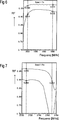
Die
Der entsprechende Serienzweig SZ des Filters verbindet einen ersten Anschluss T1 mit einem zweiten Anschluss T2, die jeweils dem Filterein- bzw. Filterausgang zugeordnet sind. Nicht eingezeichnet sind zusätzliche Reaktanzen, wie sie in einem herkömmlichen Ladder-Type-Design eingesetzt sein können, die jedoch den Kern der Erfindung nicht betreffen. The corresponding series branch SZ of the filter connects a first terminal T1 to a second terminal T2, which are each assigned to the filter inlet or filter outlet. Not shown are additional reactances, such as may be used in a conventional ladder-type design, but which do not relate to the gist of the invention.
Der Wert der Parallelinduktivität wird beispielsweise zwischen 2 und 4 nH gewählt, was einen diskreten, über eine Leiterbahninduktivität hinausgehenden Aufbau erfordert, beispielsweise eine Kupferspule.The value of the parallel inductance is chosen, for example, between 2 and 4 nH, which requires a discrete structure beyond a printed conductor inductance, for example a copper coil.
Im Vergleich zur
Verglichen mit
Gemäß einem weiteren Ausführungsbeispiel werden zusätzlich zu den vorgeschlagenen erfindungsgemäßen Maßnahmen noch die Serienzweige des RX-Filters und des TX-Filters über einen Serienresonator an den gemeinsamen Antennenanschluss angebunden und die statische Kapazität CSRS dieses Serienresonators erniedrigt.According to a further embodiment, in addition to the proposed measures according to the invention, the series branches of the RX filter and the TX filter are also connected to the common antenna connection via a series resonator and the static capacitance CS RS of this series resonator is lowered.
In
In
Vor allem liegt das Minimum der Reflexion durch Verschiebung der Resonanz der Nebenmode (siehe
Die Erfindung konnte nur anhand weniger Ausführungsbeispiele dargestellt werden, ist aber nicht auf diese beschränkt. Prinzipiell ist die Erfindung auf alle Konstellationen anwendbar, in denen die störende Nebenmode im Bereich eines zu unterdrückenden Gegenbands zu liegen kommt. Die störende Nebenmode muss keine Platten-Mode sein, sondern kann eine beliebige andere parasitäre Mode sein. Die Erfindung ist auch nicht nur auf das genannte Ausführungsbeispiel eines B1B3 Carrier Aggregation Modes beschränkt. Sie ist immer dann einsetzbar, wenn der Abstand zwischen Hauptfrequenz und Nebenmode ungefähr dem Abstand eines Gegenbands vom Hauptband entspricht. The invention could be illustrated only by means of a few embodiments, but is not limited to these. In principle, the invention can be applied to all constellations in which the disturbing secondary mode comes to rest in the region of an opposing band to be suppressed. The interfering slave mode need not be a plate mode, but may be any other parasitic mode. The invention is not limited to the said embodiment of a B1B3 carrier aggregation mode. It can be used whenever the distance between the main frequency and the secondary mode is approximately the same as the distance of a main band from the main band.
In ähnlicher Weise ist auch das Substratmaterial der SAW-Filter nicht auf das genannte Lithium-Niobat beschränkt und kann ein beliebiges anderes einkristallines Substrat umfassen. Likewise, the substrate material of the SAW filters is not limited to said lithium niobate and may include any other single crystalline substrate.
Die Anzahl sowohl serieller Resonatoren RS als auch paralleler Resonatoren RP kann von dem in
Ein SAW-Filter kann einen Schichtaufbau oberhalb des piezoelektrischen Substrats aufweisen, der weitere hier nicht genannte Moden ermöglicht. Weiterhin kann der Abstand von Nebenmoden zur Hauptmode durch entsprechend veränderte Materialien verändert werden, sodass die Erfindung dadurch auch auf weitere Konstellationen anwendbar ist. A SAW filter may have a layer structure above the piezoelectric substrate, which allows further modes not mentioned here. Furthermore, the distance of secondary modes to the main mode can be changed by correspondingly changed materials, so that the invention is thereby applicable to other constellations.
BezugszeichenlisteLIST OF REFERENCE NUMBERS
-
- B1RXB1RX
-
Rx Frequenzbereich von Band 1Rx frequency range of
volume 1 - B1TXB1TX
-
Tx Frequenzbereich von Band 1Tx frequency range of
volume 1 - CRS1 C RS1
- statische Kapazität von RS1static capacity of RS1
- DPXDPX
- Duplexerduplexer
- fPM f PM
- Resonanzfrequenz der Platten-Mode von RPResonance frequency of RP-plate mode
- fRP f RP
- Hauptresonanz des ParallelresonatorsMain resonance of the parallel resonator
- KSKS
- SiO2 SchichtSiO 2 layer
- LPLP
- Parallelinduktivitätparallel inductance
- pp
- Fingerperiodefinger period
- PZPZ
- Parallelzweigeparallel branches
- RFRF
- Reflexionsfaktorreflection factor
- RPRP
- Parallelresonatorparallel resonator
- RSRS
- SerienresonatorenSeries resonators
- RS1RS1
- Erster SerienresonatorFirst series resonator
- SZSZ
- Serienzweigseries branch
- T1T1
- Filtereingangfilter input
- T2T2
- Filterausgangfilter output
Claims (10)
Priority Applications (2)
| Application Number | Priority Date | Filing Date | Title |
|---|---|---|---|
| DE102015114751.3A DE102015114751A1 (en) | 2015-09-03 | 2015-09-03 | SAW filter |
| PCT/EP2016/067654 WO2017036673A1 (en) | 2015-09-03 | 2016-07-25 | Saw filter |
Applications Claiming Priority (1)
| Application Number | Priority Date | Filing Date | Title |
|---|---|---|---|
| DE102015114751.3A DE102015114751A1 (en) | 2015-09-03 | 2015-09-03 | SAW filter |
Publications (1)
| Publication Number | Publication Date |
|---|---|
| DE102015114751A1 true DE102015114751A1 (en) | 2017-03-09 |
Family
ID=56611235
Family Applications (1)
| Application Number | Title | Priority Date | Filing Date |
|---|---|---|---|
| DE102015114751.3A Withdrawn DE102015114751A1 (en) | 2015-09-03 | 2015-09-03 | SAW filter |
Country Status (2)
| Country | Link |
|---|---|
| DE (1) | DE102015114751A1 (en) |
| WO (1) | WO2017036673A1 (en) |
Cited By (2)
| Publication number | Priority date | Publication date | Assignee | Title |
|---|---|---|---|---|
| DE102016114071B3 (en) * | 2016-07-29 | 2018-01-25 | Snaptrack, Inc. | Electro-acoustic filter with reduced plate modes |
| WO2019170339A1 (en) * | 2018-03-05 | 2019-09-12 | RF360 Europe GmbH | Acoustic wave devices with improved spurious mode suppression |
Citations (1)
| Publication number | Priority date | Publication date | Assignee | Title |
|---|---|---|---|---|
| US20140218129A1 (en) * | 2011-11-30 | 2014-08-07 | Panasonic Corporation | Ladder-type elastic wave filter and antenna duplexer using same |
Family Cites Families (4)
| Publication number | Priority date | Publication date | Assignee | Title |
|---|---|---|---|---|
| JP2002141771A (en) * | 2000-08-21 | 2002-05-17 | Murata Mfg Co Ltd | Surface acoustic wave filter |
| JP2003298392A (en) * | 2002-03-29 | 2003-10-17 | Fujitsu Media Device Kk | Filter chip and filter device |
| JP2010011300A (en) * | 2008-06-30 | 2010-01-14 | Murata Mfg Co Ltd | Resonator device, filter including the same, and duplexer |
| JP5565474B2 (en) * | 2010-12-29 | 2014-08-06 | 株式会社村田製作所 | Surface acoustic wave device |
-
2015
- 2015-09-03 DE DE102015114751.3A patent/DE102015114751A1/en not_active Withdrawn
-
2016
- 2016-07-25 WO PCT/EP2016/067654 patent/WO2017036673A1/en active Application Filing
Patent Citations (1)
| Publication number | Priority date | Publication date | Assignee | Title |
|---|---|---|---|---|
| US20140218129A1 (en) * | 2011-11-30 | 2014-08-07 | Panasonic Corporation | Ladder-type elastic wave filter and antenna duplexer using same |
Non-Patent Citations (1)
| Title |
|---|
| LINK, A.; WARDER, P.: Golden Age for Filter Design. In: IEEE Microwave Magazine, Vol. 16, 2015, No. 7, S. 60-72. * |
Cited By (2)
| Publication number | Priority date | Publication date | Assignee | Title |
|---|---|---|---|---|
| DE102016114071B3 (en) * | 2016-07-29 | 2018-01-25 | Snaptrack, Inc. | Electro-acoustic filter with reduced plate modes |
| WO2019170339A1 (en) * | 2018-03-05 | 2019-09-12 | RF360 Europe GmbH | Acoustic wave devices with improved spurious mode suppression |
Also Published As
| Publication number | Publication date |
|---|---|
| WO2017036673A1 (en) | 2017-03-09 |
Similar Documents
| Publication | Publication Date | Title |
|---|---|---|
| DE102005051852B4 (en) | SAW filter with broadband bandstop filter | |
| DE10246791B4 (en) | Resonant bulk acoustic wave resonator and resonator circuit | |
| DE112014006010B4 (en) | High frequency filter | |
| DE102007024895B4 (en) | Multiband filter | |
| EP1196991B1 (en) | Surface acoustic wave (saw) filter of the reactance filter type exhibiting improved stop band suppression and method for optimizing the stop band suppression | |
| DE102012108030B4 (en) | Multiplexer with reduced intermodulation products | |
| DE102015116224B4 (en) | SAW filter with additional pole | |
| DE112012002502B4 (en) | demultiplexer | |
| DE102013100286B3 (en) | Wideband filter in branching technology | |
| DE112012004229B4 (en) | splinter | |
| DE69838694T2 (en) | SAW filter with SAW interstage matching resonator | |
| DE102015116223B4 (en) | SAW filter with suppressed shear mode | |
| DE112010001174T5 (en) | Branch filter for elastic waves | |
| DE102014112676A1 (en) | Filter with improved linearity | |
| DE102010048965B4 (en) | Band-stop filter with a series connection of at least two pi-members | |
| DE102008052222A1 (en) | Antenna duplexer with high GPS suppression | |
| DE102005045372A1 (en) | Component with at least one working with acoustic waves filter | |
| DE102016112993A1 (en) | Notch filter as well as this comprehensive extractor arrangement | |
| DE102006005298B4 (en) | duplexer | |
| DE102010055648B4 (en) | filter device | |
| DE102015114751A1 (en) | SAW filter | |
| DE102015107231B4 (en) | Cascaded resonator | |
| DE102014118000A1 (en) | Arrangement with a strain gauge filter and steep right flank | |
| DE102018102832B4 (en) | Filter circuit with a notch filter | |
| DE102016106185A1 (en) | Broadband SAW filter |
Legal Events
| Date | Code | Title | Description |
|---|---|---|---|
| R012 | Request for examination validly filed | ||
| R081 | Change of applicant/patentee |
Owner name: SNAPTRACK, INC., SAN DIEGO, US Free format text: FORMER OWNER: EPCOS AG, 81669 MUENCHEN, DE |
|
| R082 | Change of representative |
Representative=s name: BARDEHLE PAGENBERG PARTNERSCHAFT MBB PATENTANW, DE |
|
| R016 | Response to examination communication | ||
| R119 | Application deemed withdrawn, or ip right lapsed, due to non-payment of renewal fee |