DE102015114458B4 - SERVO CONTROL DEVICE - Google Patents
SERVO CONTROL DEVICE Download PDFInfo
- Publication number
- DE102015114458B4 DE102015114458B4 DE102015114458.1A DE102015114458A DE102015114458B4 DE 102015114458 B4 DE102015114458 B4 DE 102015114458B4 DE 102015114458 A DE102015114458 A DE 102015114458A DE 102015114458 B4 DE102015114458 B4 DE 102015114458B4
- Authority
- DE
- Germany
- Prior art keywords
- disturbance
- speed
- transfer characteristic
- command value
- control device
- Prior art date
- Legal status (The legal status is an assumption and is not a legal conclusion. Google has not performed a legal analysis and makes no representation as to the accuracy of the status listed.)
- Active
Links
Images


Classifications
-
- G—PHYSICS
- G05—CONTROLLING; REGULATING
- G05B—CONTROL OR REGULATING SYSTEMS IN GENERAL; FUNCTIONAL ELEMENTS OF SUCH SYSTEMS; MONITORING OR TESTING ARRANGEMENTS FOR SUCH SYSTEMS OR ELEMENTS
- G05B19/00—Program-control systems
- G05B19/02—Program-control systems electric
- G05B19/18—Numerical control [NC], i.e. automatically operating machines, in particular machine tools, e.g. in a manufacturing environment, so as to execute positioning, movement or co-ordinated operations by means of program data in numerical form
- G05B19/401—Numerical control [NC], i.e. automatically operating machines, in particular machine tools, e.g. in a manufacturing environment, so as to execute positioning, movement or co-ordinated operations by means of program data in numerical form characterised by control arrangements for measuring, e.g. calibration and initialisation, measuring workpiece for machining purposes
- G05B19/4015—Numerical control [NC], i.e. automatically operating machines, in particular machine tools, e.g. in a manufacturing environment, so as to execute positioning, movement or co-ordinated operations by means of program data in numerical form characterised by control arrangements for measuring, e.g. calibration and initialisation, measuring workpiece for machining purposes going to a reference at the beginning of machine cycle, e.g. for calibration
-
- G—PHYSICS
- G05—CONTROLLING; REGULATING
- G05B—CONTROL OR REGULATING SYSTEMS IN GENERAL; FUNCTIONAL ELEMENTS OF SUCH SYSTEMS; MONITORING OR TESTING ARRANGEMENTS FOR SUCH SYSTEMS OR ELEMENTS
- G05B19/00—Program-control systems
- G05B19/02—Program-control systems electric
- G05B19/18—Numerical control [NC], i.e. automatically operating machines, in particular machine tools, e.g. in a manufacturing environment, so as to execute positioning, movement or co-ordinated operations by means of program data in numerical form
- G05B19/19—Numerical control [NC], i.e. automatically operating machines, in particular machine tools, e.g. in a manufacturing environment, so as to execute positioning, movement or co-ordinated operations by means of program data in numerical form characterised by positioning or contouring control systems, e.g. to control position from one programmed point to another or to control movement along a programmed continuous path
-
- G—PHYSICS
- G05—CONTROLLING; REGULATING
- G05B—CONTROL OR REGULATING SYSTEMS IN GENERAL; FUNCTIONAL ELEMENTS OF SUCH SYSTEMS; MONITORING OR TESTING ARRANGEMENTS FOR SUCH SYSTEMS OR ELEMENTS
- G05B2219/00—Program-control systems
- G05B2219/30—Nc systems
- G05B2219/34—Director, elements to supervisory
- G05B2219/34013—Servocontroller
-
- G—PHYSICS
- G05—CONTROLLING; REGULATING
- G05B—CONTROL OR REGULATING SYSTEMS IN GENERAL; FUNCTIONAL ELEMENTS OF SUCH SYSTEMS; MONITORING OR TESTING ARRANGEMENTS FOR SUCH SYSTEMS OR ELEMENTS
- G05B2219/00—Program-control systems
- G05B2219/30—Nc systems
- G05B2219/42—Servomotor, servo controller kind till VSS
- G05B2219/42005—Disturbance decoupling, rejection, suppression
Landscapes
- Engineering & Computer Science (AREA)
- Human Computer Interaction (AREA)
- Manufacturing & Machinery (AREA)
- Physics & Mathematics (AREA)
- General Physics & Mathematics (AREA)
- Automation & Control Theory (AREA)
- Feedback Control In General (AREA)
- Control Of Position Or Direction (AREA)
- Numerical Control (AREA)
- Power Engineering (AREA)
- Control Of Throttle Valves Provided In The Intake System Or In The Exhaust System (AREA)
- Control Of Motors That Do Not Use Commutators (AREA)
Abstract
Servosteuervorrichtung für eine numerisch gesteuerte Maschine, in der eine Zielanlage durch einen Servomotor zur Steuerung einer Position oder Geschwindigkeit der Zielanlage entsprechend einem Positionsbefehlswert oder einem Geschwindigkeitsbefehlswert angetrieben wird, der von einer Host-Vorrichtung ausgegeben wird, wobei die Servosteuervorrichtung umfasst:
- ein Störungsunterdrückungssystem zur Schätzung eines Störungswerts, der in die Zielanlage eingegeben wird, und zur Eingabe des Schätzwertes zurück zu einer Steuereingabe, wobei das Störungsunterdrückungssystem umfasst:
- einen Störungsschätzfehlerberechner zur Berechnung eines Störungsschätzfehlersignals auf Grundlage einer detektierten Geschwindigkeit der Zielanlage und einer Anlagenmodellgeschwindigkeit entsprechend einem Antriebskraftbefehlswert für den Servomotor, und
- eine Störungsunterdrückungssteuerung, die durch µ-Design konfiguriert ist, zur Verbesserung einer Störungsunterdrückungsleistung, die einem mittleren bis niedrigen Bereichs einer Frequenzdomäne zugeordnet ist, während verhindert wird, dass sich die Befehlsfolgeleistung in einem hohen Bereich der Frequenzdomäne ändert, wobei das Störungsschätzfehlersignal in der Störungsunterdrückungssteuerung verstärkt wird und zurück zu dem Antriebskraftbefehlswert gegeben wird.
- a disturbance suppression system for estimating a disturbance value input to the target system and for inputting the estimated value back to a control input, the disturbance suppression system comprising:
- a disturbance estimation error calculator for calculating a disturbance estimation error signal based on a detected speed of the target equipment and a equipment model speed corresponding to a driving force command value for the servo motor, and
- a disturbance suppression controller configured by µ-design for improving a disturbance suppression performance associated with a middle to low range of a frequency domain while preventing the command following performance from changing in a high range of the frequency domain, wherein the disturbance estimation error signal is amplified in the disturbance suppression controller and fed back to the driving force command value.
Description
TECHNISCHES GEBIETTECHNICAL FIELD
Die vorliegende Erfindung betrifft eine Servosteuervorrichtung und insbesondere eine Geschwindigkeitssteuervorrichtung und eine Positionssteuervorrichtung zur Steuerung von Achsen in einer numerisch gesteuerten Maschine.The present invention relates to a servo control device and, more particularly, to a speed control device and a position control device for controlling axes in a numerically controlled machine.
ERFINDUNGSHINTERGRUNDBACKGROUND OF THE INVENTION
Im allgemeinen müssen Servosteuervorrichtungen (wie etwa Geschwindigkeitssteuervorrichtungen und Positionssteuervorrichtungen), die zur Steuerung der Achsen in numerisch gesteuerten Maschinen verwendet werden, eine gute Systemstabilität aufweisen (einschließlich einer guten Vibrationsunterdrückung), und ein hohes Niveau bezüglich der Befehlsfolgeleistung und Störungsunterdrückungsleistung.
Hier kann die Befehlsfolgeleistung durch Bildung eines Vorwärtskopplungssystems (nicht dargestellt) verbessert werden. Wenn indessen die Empfindlichkeitsfunktion S in dem mittleren bis niedrigeren Frequenzbereich minimiert wird, um die Störungsunterdrückungsleistung zu verbessern, verbreitert sich zwangsläufig die Bandbreite der komplementären Empfindlichkeitsfunktion T zu einem großen Bereich. Dies führt oft zu Problemen wie etwa dem Auftreten von Vibrationen in einem hohen Frequenzband und einer Abnahme der Systemstabilität. Um solche Probleme zu vermeiden, wurde nach dem Stand der Technik ein Steuerungsverfahren zur Unterdrückung lediglich der Störungen in einer kleineren Schleife vorgeschlagen. Als ein herkömmliches Störungsunterdrückungssteuerverfahren wurde ein bekanntes Steuerverfahren vorgeschlagen (nachfolgend als Störungsbeobachterverfahren bezeichnet), in welchem eine Zielanlage eines Modells niedrigerer Ordnung geschätzt wurde, zur Schätzung einer Störung d, die in die Zielanlage eingegeben wird, und zur Bereitstellung von Rückkopplungsdaten zu einem Steuerungseingang zur Beseitigung der Störung d, so dass die Störung unterdrückt wird.Here, the command following performance can be improved by forming a feedforward system (not shown). Meanwhile, when the sensitivity function S is minimized in the middle to lower frequency range to improve the disturbance suppression performance, the bandwidth of the complementary sensitivity function T inevitably widens to a large range. This often leads to problems such as the occurrence of vibration in a high frequency band and a decrease in system stability. In order to avoid such problems, a control method for suppressing only the disturbances in a smaller loop has been proposed in the prior art. As a conventional disturbance suppression control method, a known control method (hereinafter referred to as a disturbance observer method) has been proposed in which a target plant of a lower order model is estimated, a disturbance d input to the target plant is estimated, and feedback data is provided to a control input for eliminating the disturbance d so that the disturbance is suppressed.
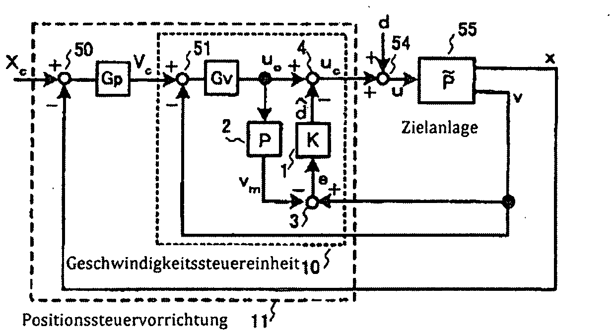
Ein Störungsbeobachter 53 speichert intern ein Modell niedrigerer Ordnung der Zielanlage 55 und gibt einen Störungsschätzwert ^d aus, der aus der motorgenierten Antriebskraft uc und der Motorgeschwindigkeit v berechnet wird. Ein Antriebskraftbefehlswert u0, welcher eine Ausgabe des Geschwindigkeitsabweichungsverstärkers Gv ist, wird als motorgenerierte Antriebskraft uc, die durch Subtraktion des Störungsschätzwerts ^d vom Antriebskraftbefehlswert u0 erhalten wird, in einen Subtrahierer 52 gegeben. Zur Steuerung einer Treiberposition x (oder einer Motorposition, die indirekt die Treiberposition anzeigt), exakt entsprechend einem Positionsbefehlswert Xc subtrahiert eine Positionssteuervorrichtung 101 die Treiberposition x vom Positionsbefehlswert Xc in einem Subtrahierer 50 zur Ermittlung einer Positionsabweichung und verstärkt die Positionsabweichung in einem Positionsabweichungsverstärker Gp. Eine verstärkte Ausgabe aus der Positionssteuervorrichtung 101 wird als Geschwindigkeitsbefehlswert Vc an die Geschwindigkeitssteuereinheit 100 weitergegeben.A
In der herkömmlichen Positionssteuervorrichtung, in welcher das zuvor beschriebene Störungsbeobachterverfahren angewendet wird, wird der Störungsschätzwert ^d als ein präziser Schätzwert der Störung d erhalten, solange eine Übertragungscharakteristik ~P der Zielanlage einer Übertragungscharakteristik P des Modells niedrigerer Ordnung entspricht, die in dem Störungsbeobachter gespeichert ist, und die Störung d kann durch Rückkopplung des genauen Störungsschätzwerts ^d beseitigt werden. Auf diese Weise kann die Störungsunterdrückungsleistung verbessert werden, ohne dass dies einen Einfluss auf die Befehlsfolgeleistung hat. Da jedoch im Allgemeinen die Übertragungscharakteristik ~P der Zielanlage nicht der Übertragungscharakteristik P des Modells niedrigerer Ordnung entspricht, insbesondere in einem Hochfrequenzband, kann der Störungsschätzwert ^d, der zurückgegeben werden soll, Daten einer sozusagen unbeabsichtigten Zustandsrückkopplung enthalten. Dies übt oft einen negativen Einfluss auf die Befehlsfolgeleistung aus und führt zu Vibrationen.In the conventional position control device in which the above-described disturbance When the disturbance observer method is applied, as long as a transfer characteristic ~ P of the target equipment corresponds to a transfer characteristic P of the lower-order model stored in the disturbance observer, the disturbance estimate ^d is obtained as an accurate estimate of the disturbance d, and the disturbance d can be eliminated by feeding back the accurate disturbance estimate ^d. In this way, the disturbance suppression performance can be improved without having an influence on the command following performance. However, since in general the transfer characteristic ~ P of the target equipment does not correspond to the transfer characteristic P of the lower-order model, especially in a high frequency band, the disturbance estimate ^d to be returned may contain data of what is called an unintended state feedback. This often exerts a negative influence on the command following performance and leads to vibration.
Anhand von ![]()
![]()
Hierbei repräsentiert I1 einen Seitenantriebsträgheitsmoment, I2 repräsentiert ein Seitenlastträgheitsmoment und ζ repräsentiert einen Dämpfungsfaktor. Dann ist das Modell niedrigerer Ordnung, das in dem Störungsbeobachter gespeichert ist, als ein Einfachinertialsystem definiert, und die Übertragungscharakteristik P des Modells ist derart definiert, dass sie die Übertragungscharakteristik ~P der Zielanlage in einem niedrigen Frequenzbereich durch Gleichung (2) wie folgt trifft.![]()
![]()
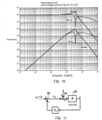
Die Operation der Ausgabe des Störungsschätzwerts ^d, die von dem Störungsbeobachter 53 ausgeführt wird, kann in gleicher Weise durch eine Operation ausgedrückt werden, in der in einem Subtrahierer 56 die motorgenerierte Antriebskraft uc von der Motorgeschwindigkeit v subtrahiert wird, die mit einer umgekehrten Übertragungscharakteristik P-1 des Modells niedrigerer Ordnung multipliziert wird, und Multiplikation des subtrahierten Ergebnisses mit einer Übertragungscharakteristik K0 in einem Übertragungsfunktionsblock 57. Die Übertragungscharakteristik K0 im Übertragungsfunktionsblock 57, die unter Verwendung einer Beobachterverstärkung ω0 als K0 = I · ω0 ausgedrückt werden kann, dient als primäre Tiefpassfiltercharakteristik in der unten angegebenen Gleichung (3).![]()
![]()
Hier sind die Parameter, die mit der Übertragungscharakteristik ~P festgelegt sind, festgelegt als I1 = 0.2 [kgm2], I2 = 0.4 [kgm2], ζ = 0.005, ωp = 628 [rad/s], und ωz = 364 [rad/s], und der Geschwindigkeitsabweichungsverstärker Gv wird geeignet unter der Bedingung bestimmt, dass das Störungsbeobachterverfahren nicht angewendet wird (ω0 = 0). Frequenzverläufe (Vc, d → v, v2) der Geschwindigkeitssteuereinheit 100, die mit den oben genannten Parametern und dem Geschwindigkeitsabweichungsverstärker Gv erhalten werden, sind in
Die Störungsunterdrückungsleistung, die durch die Frequenzverläufe (d → v, v2) repräsentiert wird, wird in dem mittleren bis niedrigen Bereich durch Anwendung des Störungsbeobachterverfahrens verbessert. Wie jedoch aus
Wie die Befehlsfolgeleistung durch das Störungsbeobachterverfahren beeinträchtigt wird, lässt sich aus dem Folgenden verstehen. Da die Übertragungscharakteristik K0 in dem Übertragungsfunktionsblock 57 in
Zur Erfassung der Operation des Störungsunterdrückungssystems in
In
Wie zuvor beschrieben, kann durch die herkömmliche Servosteuervorrichtung mit dem Störungsunterdrückungssystem, welches in der kleineren Schleife ausgebildet ist, mit der Absicht zur Verbesserung einer Störungsunterdrückungsleistung, die Störungsunterdrückungsleistung in dem mittleren bis niedrigen Bereich verbessert werden, während die Störungsunterdrückungsleistung andererseits das Befehlsfolgesystem beeinträchtigt und somit Vibrationen oder andere negative Einflüsse einbringt. Aufgrund dieser Einflüsse war es unmöglich, die Befehlsfolgeleistung und die Störungsunterdrückungsleistung einzeln zu gestalten. Es besteht daher ein Bedarf nach einer Servosteuervorrichtung mit einem Störungsunterdrückungssystem, das dazu in der Lage ist, ausschließlich die Störungsunterdrückungsleistung in dem mittleren bis niedrigen Bereich zu verbessern, ohne dass dies einen Einfluss auf das Befehlsfolgesystem hat.As described above, by the conventional servo control apparatus having the noise suppression system formed in the smaller loop with the intention of improving noise suppression performance, the noise suppression performance in the middle to low range can be improved, while the noise suppression performance on the other hand affects the command following system and thus introduces vibrations or other negative influences. Due to these influences, it has been impossible to design the command following performance and the noise suppression performance individually. There is therefore a need for a servo control apparatus having a noise suppression system capable of improving only the noise suppression performance in the middle to low range without having an influence on the command following system.
ZUSAMMENFASSUNGSUMMARY
Die Aufgabe wird durch die Merkmale des unabhängigen Anspruchs gelöst. Die vorliegende Erfindung erreicht dieses Ziel durch Einführung eines Störungsunterdrückungssystems in eine Servosteuervorrichtung, in der eine Komponente, die aufgrund eines Störungsschätzfehlers in einer Ausgabe einer Zielanlage enthalten ist, in einer Störungsunterdrückungsstörung verstärkt wird, die einen Frequenzverlauf entsprechend der Größe eines Anlagefehlers aufweist, der eine Differenz in der Übertragungscharakteristik zwischen der Zielanlage und dem Anlagemodell ist, und in die Steuereingabe zurückgeführt wird.The object is solved by the features of the independent claim. The present invention achieves this object by introducing a disturbance suppression system into a servo control apparatus in which a component included in an output of a target plant due to a disturbance estimation error is amplified in a disturbance suppression noise having a frequency characteristic corresponding to the magnitude of a plant error, which is a difference in transfer characteristics between the target plant and the plant model, and fed back into the control input.
In der Servosteuervorrichtung gemäß der vorliegenden Erfindung wird ein Zielanlagenmodell dazu verwendet, ein Störungsschätzfehlersignal zu berechnen. Das Störungsunterdrückungssystem ist dazu ausgebildet, dass Störungsschätzfehlersignal in größerem Umfang in einem mittleren bis niedrigen Frequenzbereich zu verstärken, in welchem der Anlagenfehler klein genug ist, um das Störungsschätzfehlersignal mit einem hohen Genauigkeitsgrad zu detektieren, und das Störungsschätzfehlersignal in geringerem Umfang in einem höheren Frequenzbereich zu verstärken, in welchem der Anlagefehler groß genug ist, um die Genauigkeit der Detektion des Störungsschätzfehlersignals zu beinträchtigen, und das Störungsschätzfehlersignal, das auf irgendeine Weise verstärkt worden ist, zu der Steuerungseingabe zurückzugeben. Durch das so aufgebaute Störungsunterdrückungssystem kann eine Verbesserung der Störungsunterdrückungsleistung in dem mittleren bis niedrigen Bereich ausschließlich erreicht werden, ohne dass die Befehlsfolgeleistung in dem gesamten Frequenzbereich beeinflusst wird. Dies hat die vorteilhaften Wirkungen, dass keine Vibrationen ausgeübt werden, die durch Bildung des Störungsunterdrückungssystems in einer kleineren Schleife verursacht werden, und dass somit die Störungsunterdrückungsleistung unabhängig von der Befehlsfolgeleistung gehandhabt werden kann. Da ferner verhindert wird, dass sich alle Eigenschaften in dem hohen Bereich ändern, wird sichergestellt, dass die Stabilität des Geschwindigkeitssteuerungssystems und des Positionssteuersystems verschlechtert.In the servo control apparatus according to the present invention, a target plant model is used to calculate a disturbance estimation error signal. The disturbance suppression system is configured to amplify the disturbance estimation error signal to a greater extent in a medium to low frequency range in which the plant error is small enough to detect the disturbance estimation error signal with a high degree of accuracy, and to amplify the disturbance estimation error signal to a lesser extent in a higher frequency range in which the plant error is large enough to affect the accuracy of detection of the disturbance estimation error signal, and to return the disturbance estimation error signal which has been amplified in some way to the control input. By the disturbance suppression system thus constructed, improvement of the disturbance suppression performance in the medium to low range can be achieved exclusively without affecting the command following performance in the entire frequency range. This has the advantageous effects of not exerting vibrations caused by forming the disturbance suppression system in a smaller loop, and thus the disturbance suppression performance can be handled independently of the command following performance. Furthermore, since all the characteristics in the high range are prevented from changing, it is ensured that the stability of the speed control system and the position control system is not deteriorated.
KURZBESCHREIBUNG DER ZEICHNUNGENBRIEF DESCRIPTION OF THE DRAWINGS
Die vorliegende Erfindung wird im Folgenden anhand der beigefügten Zeichnungen beschrieben, in welchen sich gleiche Bezugszeichen auf gleiche Teile in verschiedenen Ansichten beziehen.
-
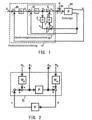
1 ist ein Blockdiagramm zur Darstellung eines Aufbaus einer Positionssteuervorrichtung gemäß einer Ausführungsform der vorliegenden Erfindung; -
2 ist ein Blockdiagramm zur Erläuterung eines Verfahrens zur Gestaltung einer Störungsunterdrückungssteuerung gemäß der vorliegenden Erfindung; -
3 ist ein Diagramm zur Erläuterung eines Beispiels von Frequenzverläufen für jeden Block in2 ; -
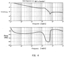
4 ist ein Diagramm zur Erläuterung eines Beispiels von Frequenzverläufen der Störungsunterdrückungssteuerung gemäß der vorliegenden Erfindung; -
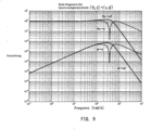
5 ist ein Diagramm zur Erläuterung eines Beispiels von Frequenzverläufen einer Geschwindigkeitssteuereinheit inder Positionssteuervorrichtung aus 1 ; -
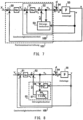
6 ist ein Diagramm zur Darstellung eines schematischen Aufbaus einer typischen Servosteuervorrichtung; -
7 ist ein Blockdiagramm zur Darstellung eines Beispiels einer herkömmlichen Positionssteuervorrichtung, in welcher ein Störungsbeobachterverfahren angewendet wird; -
8 ist ein Blockdiagramm, das im Einzelnen einen beispielhaften Aufbau einer Geschwindigkeitssteuereinheit in7 zeigt; -
9 ist ein Diagramm, das ein Beispiel von Frequenzverläufen in einer herkömmlichen Geschwindigkeitssteuereinheit zeigt, in der kein Störungsbeobachterverfahren angewendet wird; -
10 ist ein Diagramm zur Darstellung eines Beispiels von Frequenzverläufen einer herkömmlichen Geschwindigkeitssteuereinheit, in der das Störungsbeobachterverfahren angewendet wird; -
11 ist ein Blockdiagramm zur Darstellung einer Anordnung, die erhalten wird durch äquivalente Umwandlung einer Störungsunterdrückungseinheit, wie sie in8 dargestellt ist und -
12 ist ein Blockdiagramm zur Darstellung eines Aufbaus einer herkömmlichen Geschwindigkeitssteuervorrichtung.
-
1 is a block diagram showing a structure of a position control device according to an embodiment of the present invention; -
2 is a block diagram for explaining a method of designing a disturbance suppression control according to the present invention; -
3 is a diagram to explain an example of frequency responses for each block in2 ; -
4 is a diagram for explaining an example of frequency characteristics of the noise suppression control according to the present invention; -
5 is a diagram for explaining an example of frequency characteristics of a speed control unit in the position control device of1 ; -
6 is a diagram showing a schematic structure of a typical servo control device; -
7 is a block diagram showing an example of a conventional position control apparatus in which a disturbance observer method is applied; -
8 is a block diagram showing in detail an exemplary structure of a speed control unit in7 shows; -
9 is a diagram showing an example of frequency waveforms in a conventional speed control unit in which no disturbance observer method is applied; -
10 is a diagram showing an example of frequency characteristics of a conventional speed control unit in which the disturbance observer method is applied; -
11 is a block diagram showing an arrangement obtained by equivalently converting a noise suppression unit as shown in8 is shown and -
12 is a block diagram showing a structure of a conventional speed control device.
BESCHREIBUNG DER AUSFÜHRUNGSFORMENDESCRIPTION OF THE EMBODIMENTS
In der folgenden Beschreibung wird die vorliegende Erfindung anhand eines Ausführungsbeispiels mit Bezug auf die Zeichnungen beschrieben. In der vorliegenden Erfindung wird ein Störungsunterdrückungssystem ebenfalls in einer kleineren Schleife gebildet, durch welche Daten zu einem Steuereingang zurückgeführt werden, wie es auch herkömmlich der Fall ist. Zunächst wird eine Anfrage zur Bildung des Störungsunterdrückungssystems, welche keine Vibrationen induziert, ersetzt, wie oben beschrieben, durch ein Problem der Auffindung einer Übertragungscharakteristik K0, welche es ermöglicht, dass ein Rückkopplungsbetrag, der in den Steuereingang eingegeben wird, in einem Frequenzbereich reduziert wird, in welchem ein Anlagenfehler, der durch eine Differenz zwischen Übertragungscharakteristiken ~P und P repräsentiert wird, größer wird. Die Lösung dieses Problems kann eine Veränderung in der Befehlsfolgeleistung in einem hohen Frequenzbereich aufgrund der Bildung des Störungsunterdrückungssystems verhindern. Zweitens wird ein äquivalenter Block, der in
Wenn der Anlagenfehler als Multiplikationsvariable dargestellt wird, ist eine gewichtete Übertragungsfunktion Wm in ![]()
![]()
Hier kann eine Übertragungscharakteristik M22 für w2 → z2 durch Gleichung (5) wie folgt ausgedrückt werden.![]()
![]()
Da Wm sich in dem hohen Bereich vergrößert, entspricht die Aufgabe der Schaffung einer Übertragungscharakteristik K, die es ermöglicht, dass Gleichung (5) minimiert wird, dem oben beschriebenen Problem, zu verhindern, dass sich die Steuerfolgeleistung in dem hohen Bereich verändert.Since W m increases in the high range, the task of providing a transfer characteristic K that allows equation (5) to be minimized corresponds to the problem described above of preventing the control follower performance from changing in the high range.
Im Folgenden wird eine Übertragungsfunktion M11 für w1 → z1 durch Gleichung (6) wie folgt ausgedrückt.![]()
![]()
Wenn die gewichtete Übertragungsfunktion Wd so ausgewählt wird, dass sie dem Phasensystem mit stabilem Minimum entspricht, was einen Zuwachs in dem mittleren bis niedrigeren Bereich zeigt, entspricht eine Aufgabe der Schaffung der Transfercharakteristik K, die eine Minimierung von Gleichung (6) zulässt, dem Problem der Verbesserung der Störungsunterdrückungsleistung in dem mittleren bis niedrigen Bereich.When the weighted transfer function Wd is selected to correspond to the stable minimum phase system showing an increase in the middle to low range, a task of creating the transfer characteristic K that allows minimization of equation (6) corresponds to the problem of improving the interference suppression performance in the middle to low range.
Da nämlich, wie bereits oben beschrieben, das Problem, in welchem die zwei oben beschriebenen Erfordernisse formuliert sind, in der Übertragungsmatrix M enthalten ist, wird die Störungsunterdrückungssteuerung K, welche eine allgemeine Lösung sein wird, erhalten durch Lösung des robusten Steuerproblems. Die unten beschriebene Gleichung (7) stellt eine Struktur der Übertragungsmatrix M dar, die nicht diagonale Elemente enthält.
[Ausdruck 1] 
[Expression 1]
In einem Verfahren zur Lösung des robusten Steuerproblems ist es aufgrund der Tatsache, dass die nicht diagonalen Elemente in Gleichung (7) nicht in der Formulierung der Bedingungen enthalten sind, unerwünscht, dass die nicht diagonalen Elemente eine Beschränkung bezüglich der Bildung der Störungsunterdrückungssteuerung K darstellen. Dementsprechend wird gemäß der vorliegenden Erfindung das robuste Steuerproblem mit einem µ-Design gelöst, so dass die nicht diagonalen Elemente mit einem Skalierungsfaktor multipliziert werden, um die Beschränkung des Designs zu minimieren.In a method for solving the robust control problem, due to the fact that the off-diagonal elements in equation (7) are not included in the formulation of the constraints, it is undesirable that the off-diagonal elements represent a constraint on the formation of the disturbance rejection control K. Accordingly, according to the present invention, the robust control problem is solved with a µ design such that the off-diagonal elements are multiplied by a scaling factor to minimize the constraint of the design.
Die im Folgenden gegebene Gleichung (8) zeigt die Struktur der gewichteten Übertragungsfunktion Wm, die in dieser Ausführungsform verwendet wird und so bestimmt ist, dass sie |1 - ~P / P| der Frequenzverläufe abdeckt.
[Ausdruck 2]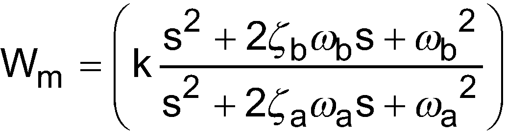
[Expression 2]
In gleicher Weise zeigt die unten angegebene Gleichung (9) die Struktur der gewichteten Transferfunktion Wd, die so bestimmt ist, dass sie in dem mittleren bis niedrigen Bereich anwächst.
[Ausdruck 3]![]()
Hierbei ist Wd vom Tiefpass-Typ und -40 dB/dec wird für die Übertragungscharakteristik gewählt.Similarly, equation (9) below shows the structure of the weighted transfer function W d , which is determined to increase in the medium to low range.
[Expression 3] ![]()
Here, W d is of the low-pass type and -40 dB/dec is chosen for the transfer characteristic.
Der Frequenzverlauf der Störungsunterdrückungssteuerung K, die unter den oben beschriebenen Bedingungen erzeugt wird, ist in
Hier wird das Störungsschätzfehlersignal e durch Gleichung (10) wie folgt ausgedrückt.
[Ausdruck 4]![]()
[Expression 4] ![]()
Aus der Definition des Störungsschätzfehlers (d - ^d) ergibt sich, dass das Störungsschätzfehlersignal e einen Störungsschätzfehler mit einer hohen Genauigkeit in dem mittleren bis niedrigeren Bereich umfasst, in welchem der Anlagenfehler klein ist, doch einen Störungsschätzfehler, der nicht mit einer hohen Genauigkeit erhalten wird, in dem hohen Bereich umfasst, in welchem der Anlagenfehler groß ist. Somit weist das Störungsunterdrückungssystem der vorliegenden Erfindung eine Störungsstruktur auf, in welchem der Rückkopplungsbetrag, der zu dem Steuerungseingang zurückgegeben wird, vergrößert ist, während sich das Maß der Genauigkeit der Detektion des Störungsschätzfehlers vergrößert.From the definition of the disturbance estimation error (d - ^d), the disturbance estimation error signal e includes a disturbance estimation error with a high accuracy in the middle to lower range in which the equipment error is small, but includes a disturbance estimation error not obtained with a high accuracy in the high range in which the equipment error is large. Thus, the disturbance suppression system of the present invention has a disturbance structure in which the feedback amount returned to the control input is increased as the degree of accuracy of detection of the disturbance estimation error increases.
Somit wird die Übertragungscharakteristik von u0, d → u in dem Störungsunterdrückungssystem durch Gleichung (11) wie folgt ausgedrückt.
[Ausdruck 5]![]()
[Expression 5] ![]()
Da die Störungsunterdrückungssteuerung K ein Verstärker ist, der eine Verstärkung mit einer höheren Verstärkungsrate in dem mittleren bis niedrigeren Bereich durchführt, in welchem der Anlagenfehler kleiner ist, und eine niedrigere Verstärkungsrate in dem hohen Bereich verwendet, in welchem der Anlagenfehler groß ist, wird ein verbesserter Störungsunterdrückungseffekt in dem mittleren bis niedrigeren Bereich erhalten, so dass der Einfluss durch die Störung d auf die Steuereingabe u entsprechend abgeschwächt wird. Durch Gleichung (11) wird bestätigt, dass aufgrund der Tatsache, dass die Steuereingabe u erhalten wird als u ≈ u0, wenn d = 0 in dem gesamten Bereich ist, das Befehlsfolgesystem nicht durch das Störungsunterdrückungssystem beeinträchtigt wird.Since the disturbance suppression controller K is an amplifier that performs amplification at a higher amplification rate in the middle to lower range in which the equipment error is smaller and uses a lower amplification rate in the high range in which the equipment error is large, an improved disturbance suppression effect is obtained in the middle to lower range, so that the influence by the disturbance d on the control input u is correspondingly weakened. It is confirmed by equation (11) that since the control input u is obtained as u ≈ u0 when d = 0 in the entire range, the command following system is not affected by the disturbance suppression system.
[Ausdruck 6]![]()
[Expression 6] ![]()
Da die Störungsunterdrückungssteuerung K die Übertragungscharakteristik von -20 dB/dec in dem mittleren bis niedrigen Bereich aufweist, werden die Übertragungscharakteristiken der Frequenzverläufe (d → v, v2) in dem mittleren bis niedrigen Bereich steiler als diejenigen der herkömmlichen Verläufe in
Wie oben beschrieben, weist die Servosteuervorrichtung gemäß der vorliegenden Erfindung eine Struktur auf, welche das Störungsunterdrückungssystem enthält, das dazu in der Lage ist, allein die Störungsunterdrückungsleistung in dem mittleren bis niedrigen Bereich zu verbessern, ohne dass dies eine Einfluss auf die Befehlsfolgeleistung in dem gesamten Frequenzbereich hat. Da dieser Aufbau eine Änderung der Frequenzverläufe verhindern kann, die in dem hohen Bereich aufgrund des Einschlusses des Störungsunterdrückungssystems auftreten können, ist es möglich, die Befehlsfolgeleistung und die Störungsunterdrückungsleistung getrennt voneinander zu gestalten, ohne dass die Stabilität des Geschwindigkeitssteuersystems und des Positionssteuersystems beeinträchtigt wird.As described above, the servo control apparatus according to the present invention has a structure including the noise suppression system capable of improving the noise suppression performance in the middle to low range alone without affecting the command following performance in the entire frequency range. Since this structure can prevent a change in the frequency characteristics that may occur in the high range due to the inclusion of the noise suppression system, it is possible to design the command following performance and the noise suppression performance separately from each other without affecting the stability of the speed control system and the position control system.
Claims (3)
Applications Claiming Priority (2)
| Application Number | Priority Date | Filing Date | Title |
|---|---|---|---|
| JP2014179299A JP6399866B2 (en) | 2014-09-03 | 2014-09-03 | Servo control device |
| JP2014-179299 | 2014-09-03 |
Publications (2)
| Publication Number | Publication Date |
|---|---|
| DE102015114458A1 DE102015114458A1 (en) | 2016-03-03 |
| DE102015114458B4 true DE102015114458B4 (en) | 2025-02-27 |
Family
ID=55312397
Family Applications (1)
| Application Number | Title | Priority Date | Filing Date |
|---|---|---|---|
| DE102015114458.1A Active DE102015114458B4 (en) | 2014-09-03 | 2015-08-31 | SERVO CONTROL DEVICE |
Country Status (5)
| Country | Link |
|---|---|
| US (1) | US9804584B2 (en) |
| JP (1) | JP6399866B2 (en) |
| CN (2) | CN111198536B (en) |
| DE (1) | DE102015114458B4 (en) |
| IT (1) | ITUB20153225A1 (en) |
Families Citing this family (6)
| Publication number | Priority date | Publication date | Assignee | Title |
|---|---|---|---|---|
| WO2018061096A1 (en) * | 2016-09-27 | 2018-04-05 | 株式会社ハーモニック・ドライブ・システムズ | Positioning control apparatus for actuator provided with wave-motion gear device based on h∞ control |
| CN112236729B (en) * | 2018-06-15 | 2024-03-15 | 三菱电机株式会社 | CNC device |
| CN109901630B (en) * | 2019-03-01 | 2022-02-18 | 中国科学院光电技术研究所 | Double-fast-reflector platform light beam stabilizing device based on series structure |
| CN109946979B (en) * | 2019-04-25 | 2022-03-22 | 广东省智能机器人研究院 | Self-adaptive adjusting method for sensitivity function of servo system |
| KR20210050303A (en) * | 2019-10-28 | 2021-05-07 | 한국전기연구원 | Control system and method for servomotor |
| CN115431938B (en) * | 2022-09-14 | 2024-06-21 | 清华大学 | A clamping force control method for a clamping force estimation system and a vehicle braking system |
Citations (3)
| Publication number | Priority date | Publication date | Assignee | Title |
|---|---|---|---|---|
| JPH1124708A (en) | 1997-07-09 | 1999-01-29 | Yaskawa Electric Corp | Servo control device |
| DE602005001651T2 (en) | 2004-04-08 | 2007-11-22 | Fanuc Ltd. | Device for damping vibrations |
| JP2014179299A (en) * | 2013-03-15 | 2014-09-25 | Daiichi Seiko Co Ltd | Connector device |
Family Cites Families (22)
| Publication number | Priority date | Publication date | Assignee | Title |
|---|---|---|---|---|
| JPS59146485A (en) * | 1983-02-09 | 1984-08-22 | Nec Corp | Head positioning servo mechanism of magnetic disk device |
| JP2569152B2 (en) * | 1988-10-17 | 1997-01-08 | ファナック株式会社 | Servo control method |
| EP0676681B1 (en) * | 1994-04-04 | 1999-11-10 | Kabushiki Kaisha Meidensha | Inertia lowering control apparatus for suppressing axial torsional vibration in two-mass resonant system |
| JPH0922304A (en) * | 1995-07-07 | 1997-01-21 | Komatsu Ltd | Vibration suppressor |
| KR970055208A (en) * | 1995-12-28 | 1997-07-31 | 김광호 | Speed Control Method and Speed Control Device of Servo Motor |
| JP3239060B2 (en) * | 1996-01-31 | 2001-12-17 | シャープ株式会社 | Motor control device |
| KR100237306B1 (en) * | 1997-03-25 | 2000-01-15 | 윤종용 | Vibration Suppression Method and Apparatus for Two Inertial Resonance System |
| US6490120B1 (en) * | 1997-08-29 | 2002-12-03 | Seagate Technology Llc | Servo gain optimization using a variable convergence factor |
| JP2005135186A (en) * | 2003-10-30 | 2005-05-26 | Toshiba Corp | Reference model following control system and reference model following control method |
| JP4594898B2 (en) * | 2006-04-28 | 2010-12-08 | 東芝ストレージデバイス株式会社 | Head position control device and disk device |
| JP4769141B2 (en) * | 2006-08-03 | 2011-09-07 | 東芝ストレージデバイス株式会社 | Head position control method, head position control device, and disk device |
| JP4673326B2 (en) * | 2007-01-11 | 2011-04-20 | オークマ株式会社 | Rotary shaft position control device |
| JP4944806B2 (en) * | 2007-10-09 | 2012-06-06 | オークマ株式会社 | Position control device |
| JP5457894B2 (en) * | 2010-03-17 | 2014-04-02 | オークマ株式会社 | Full closed position controller |
| CN101989080A (en) * | 2010-12-03 | 2011-03-23 | 沈阳工业大学 | Method for realizing contour machining by using variable gain zero phase error tracking and disturbance observation |
| CN103492962B (en) * | 2011-04-15 | 2016-11-02 | 株式会社明电舍 | Periodic disturbance suppression device and periodic disturbance suppression method |
| JP5273575B2 (en) * | 2011-09-01 | 2013-08-28 | 株式会社安川電機 | Electric motor control device |
| US8737013B2 (en) * | 2011-11-16 | 2014-05-27 | Western Digital Technologies, Inc. | Disk drive selecting disturbance signal for feed-forward compensation |
| US8711511B2 (en) * | 2012-06-19 | 2014-04-29 | International Business Machines Corporation | Vibration disturbance estimation and control |
| JP5836219B2 (en) * | 2012-07-20 | 2015-12-24 | 三菱電機株式会社 | Motor control device |
| JP5652678B2 (en) * | 2013-03-21 | 2015-01-14 | 株式会社安川電機 | Electric motor control device |
| CN103412484B (en) * | 2013-07-18 | 2016-06-01 | 北京控制工程研究所 | A kind of control moment gyro framework disturbing moment suppressing method |
-
2014
- 2014-09-03 JP JP2014179299A patent/JP6399866B2/en active Active
-
2015
- 2015-08-25 IT ITUB2015A003225A patent/ITUB20153225A1/en unknown
- 2015-08-31 DE DE102015114458.1A patent/DE102015114458B4/en active Active
- 2015-09-01 US US14/842,237 patent/US9804584B2/en not_active Expired - Fee Related
- 2015-09-02 CN CN202010077343.3A patent/CN111198536B/en active Active
- 2015-09-02 CN CN201510560109.5A patent/CN105388841A/en active Pending
Patent Citations (3)
| Publication number | Priority date | Publication date | Assignee | Title |
|---|---|---|---|---|
| JPH1124708A (en) | 1997-07-09 | 1999-01-29 | Yaskawa Electric Corp | Servo control device |
| DE602005001651T2 (en) | 2004-04-08 | 2007-11-22 | Fanuc Ltd. | Device for damping vibrations |
| JP2014179299A (en) * | 2013-03-15 | 2014-09-25 | Daiichi Seiko Co Ltd | Connector device |
Also Published As
| Publication number | Publication date |
|---|---|
| JP6399866B2 (en) | 2018-10-03 |
| DE102015114458A1 (en) | 2016-03-03 |
| CN111198536A (en) | 2020-05-26 |
| CN111198536B (en) | 2023-03-24 |
| US9804584B2 (en) | 2017-10-31 |
| CN105388841A (en) | 2016-03-09 |
| JP2016053825A (en) | 2016-04-14 |
| ITUB20153225A1 (en) | 2017-02-25 |
| US20160062341A1 (en) | 2016-03-03 |
Similar Documents
| Publication | Publication Date | Title |
|---|---|---|
| DE102015114458B4 (en) | SERVO CONTROL DEVICE | |
| DE112007001271T5 (en) | Servo control device | |
| DE102020201897B4 (en) | Steer-by-wire steering system for a vehicle and method for operating a steer-by-wire steering system | |
| DE602005001651T2 (en) | Device for damping vibrations | |
| DE112006001287B4 (en) | Electric motor control device | |
| DE69828348T2 (en) | Device for controlling the speed of elevators | |
| DE19920975B4 (en) | Electric power steering system | |
| DE112011101711B4 (en) | engine control device | |
| DE112013007679B4 (en) | Numerical control system and numerical control method | |
| DE102016014562A1 (en) | STEERING CONTROL DEVICE AND STEERING CONTROL METHOD | |
| DE60100260T2 (en) | Method and device for controlling electric power steering | |
| DE102016103301B4 (en) | MOTOR CONTROL UNIT WITH A FUNCTION FOR SUPPRESSING VIBRATIONS | |
| DE112015003203T5 (en) | System and method for robust active interference suppression in an electric power steering system | |
| DE102015204332A1 (en) | Method for semi-autonomous driving of a vehicle with steer-by-wire system and steer-by-wire system for regulating operation of a vehicle | |
| DE102007006383A1 (en) | Control device for an electric power operated steering system | |
| DE69810150T2 (en) | ENGINE SPEED REGULATOR AND METHOD FOR ADJUSTING THE REGULATOR GAIN | |
| DE112012004278T5 (en) | Servo-esterification device | |
| DE102014104896A1 (en) | Motor control device | |
| DE102015011113A1 (en) | Motor control system that compensates for interference between axes | |
| DE112019006874T5 (en) | Vehicle-to-vehicle distance control device | |
| DE102015007194B4 (en) | Servo control with reduced deflection of the front end point of a machine | |
| DE112006003736T5 (en) | Engine control unit and engine control method | |
| DE112014006662T5 (en) | Motor control constants computing device | |
| DE112018000468T5 (en) | A method of designing a filter of a delay compensator, control method using the same, and motor control device | |
| DE112014007197T5 (en) | DRIVE CONTROL DEVICE FOR A MULTILINGER MOTOR |
Legal Events
| Date | Code | Title | Description |
|---|---|---|---|
| R012 | Request for examination validly filed | ||
| R016 | Response to examination communication | ||
| R018 | Grant decision by examination section/examining division | ||
| R020 | Patent grant now final |