DE102012220249A1 - Guide vane collar for fluid-flow machine, has guide vanes whose ends are connected with respective opposite blade end surface that is provided with parallel radial clearance, where annular surface is provided with guide vanes - Google Patents
Guide vane collar for fluid-flow machine, has guide vanes whose ends are connected with respective opposite blade end surface that is provided with parallel radial clearance, where annular surface is provided with guide vanes Download PDFInfo
- Publication number
- DE102012220249A1 DE102012220249A1 DE201210220249 DE102012220249A DE102012220249A1 DE 102012220249 A1 DE102012220249 A1 DE 102012220249A1 DE 201210220249 DE201210220249 DE 201210220249 DE 102012220249 A DE102012220249 A DE 102012220249A DE 102012220249 A1 DE102012220249 A1 DE 102012220249A1
- Authority
- DE
- Germany
- Prior art keywords
- vane
- guide vanes
- guide
- ring
- annular surface
- Prior art date
- Legal status (The legal status is an assumption and is not a legal conclusion. Google has not performed a legal analysis and makes no representation as to the accuracy of the status listed.)
- Granted
Links
Images
Classifications
-
- F—MECHANICAL ENGINEERING; LIGHTING; HEATING; WEAPONS; BLASTING
- F01—MACHINES OR ENGINES IN GENERAL; ENGINE PLANTS IN GENERAL; STEAM ENGINES
- F01D—NON-POSITIVE DISPLACEMENT MACHINES OR ENGINES, e.g. STEAM TURBINES
- F01D5/00—Blades; Blade-carrying members; Heating, heat-insulating, cooling or antivibration means on the blades or the members
- F01D5/12—Blades
- F01D5/14—Form or construction
- F01D5/141—Shape, i.e. outer, aerodynamic form
- F01D5/142—Shape, i.e. outer, aerodynamic form of the blades of successive rotor or stator blade-rows
- F01D5/143—Contour of the outer or inner working fluid flow path wall, i.e. shroud or hub contour
-
- F—MECHANICAL ENGINEERING; LIGHTING; HEATING; WEAPONS; BLASTING
- F01—MACHINES OR ENGINES IN GENERAL; ENGINE PLANTS IN GENERAL; STEAM ENGINES
- F01D—NON-POSITIVE DISPLACEMENT MACHINES OR ENGINES, e.g. STEAM TURBINES
- F01D17/00—Regulating or controlling by varying flow
- F01D17/10—Final actuators
- F01D17/12—Final actuators arranged in stator parts
- F01D17/14—Final actuators arranged in stator parts varying effective cross-sectional area of nozzles or guide conduits
- F01D17/16—Final actuators arranged in stator parts varying effective cross-sectional area of nozzles or guide conduits by means of nozzle vanes
- F01D17/162—Final actuators arranged in stator parts varying effective cross-sectional area of nozzles or guide conduits by means of nozzle vanes for axial flow, i.e. the vanes turning around axes which are essentially perpendicular to the rotor centre line
-
- Y—GENERAL TAGGING OF NEW TECHNOLOGICAL DEVELOPMENTS; GENERAL TAGGING OF CROSS-SECTIONAL TECHNOLOGIES SPANNING OVER SEVERAL SECTIONS OF THE IPC; TECHNICAL SUBJECTS COVERED BY FORMER USPC CROSS-REFERENCE ART COLLECTIONS [XRACs] AND DIGESTS
- Y02—TECHNOLOGIES OR APPLICATIONS FOR MITIGATION OR ADAPTATION AGAINST CLIMATE CHANGE
- Y02T—CLIMATE CHANGE MITIGATION TECHNOLOGIES RELATED TO TRANSPORTATION
- Y02T50/00—Aeronautics or air transport
- Y02T50/60—Efficient propulsion technologies, e.g. for aircraft
Landscapes
- Engineering & Computer Science (AREA)
- Physics & Mathematics (AREA)
- Fluid Mechanics (AREA)
- Mechanical Engineering (AREA)
- General Engineering & Computer Science (AREA)
- Structures Of Non-Positive Displacement Pumps (AREA)
Abstract
Offenbart ist ein Leitschaufelkranz für eine Strömungsmaschine, mit einer Vielzahl von Leitschaufeln, die jeweils um ihre Hauptachse verstellbar sind, und mit einem Innenring zum radial inneren Stabilisieren der Leitschaufeln, wobei eine Ringfläche des Innenrings und/oder jeweils eine der Ringfläche zugewandte und von dieser radial beabstandete Schaufelendfläche der Leitschaufeln in einem Winkel ungleich 90° zur Hauptachse orientiert ist/sind, wobei in die Ringfläche im Verstellbereich jeder Leitschaufel eine längliche Vertiefung eingebracht ist, die mit der jeweils gegenüberliegenden Schaufelendfläche über einen Teil des Verstellbereichs der Leitschaufel einen konstanten Radialspalt bildet, eine Strömungsmaschine sowie ein Innenring.Disclosed is a guide vane ring for a turbomachine, with a plurality of guide vanes, each adjustable about their main axis, and with an inner ring for radially inner stabilization of the guide vanes, with an annular surface of the inner ring and / or in each case facing the annular surface and radially from it spaced blade end face of the guide vanes is / are oriented at an angle not equal to 90 ° to the main axis, with an elongated recess being made in the annular surface in the adjustment range of each guide vane, which with the respective opposite vane end face forms a constant radial gap over part of the adjustment range of the guide vane, a Turbo machine and an inner ring.
Description
Die Erfindung betrifft einen Leitschaufelkranz nach dem Oberbegriff des Patentanspruchs 1, eine Strömungsmaschine sowie einen Innenring.The invention relates to a guide vane ring according to the preamble of patent claim 1, a turbomachine and an inner ring.
Ein herkömmlicher Leitschaufelkranz bzw. ein Leitgitter für eine Strömungsmaschine wie ein Flugtriebwerk oder eine stationäre Gasturbine hat eine Vielzahl von Leitschaufeln, die jeweils um ihre Hauptachse verstellbar sind, und einen konischen Innenring zum radial inneren Stabilisieren der Leitschaufel. Der Innenring hat aufgrund seiner Konizität eine in Längsrichtung des Leitschaufelkranzes schräg angestellte Ringfläche, die einen Ringraum der Strömungsmaschine radial innen begrenzt und mit einer Vielzahl von gegenüberliegenden Schaufelendflächen der Leitschaufeln jeweils einen Radialspalt definiert. Die Radialspalte führen grundsätzlich zu aerodynamischen Verlusten und somit zu einer Wirkungsgradreduzierung der Strömungsmaschine. A conventional vane ring for a turbomachine such as an aircraft engine or a stationary gas turbine has a plurality of vanes, each adjustable about its major axis, and a conical inner ring for radially inner stabilizing the vane. Due to its conicity, the inner ring has an annular surface arranged obliquely in the longitudinal direction of the vane ring, which radially defines an annular space of the turbomachine and defines a radial gap with a plurality of opposite blade end surfaces of the guide vanes. The radial gaps basically lead to aerodynamic losses and thus to a reduction in efficiency of the turbomachine.
Aufgrund der schrägen Ausrichtung der Ringfläche und der Schaufelendflächen sind die Radialspalte über den Verstellbereich der Leitschaufeln unterschiedlich hoch. So sind die Radialspalte herkömmlicherweise bei einem maximal aufgesteuerten Leitschaufelkranz kleiner als im auslegungsrelevanten Betriebspunkt der Strömungsmaschine. Da jedoch auch bei dem maximal aufgesteuerten Leitschaufelkranz eine Mindestspalthöhe, bestehend aus einer Toleranzkette und einer thermischen Dehnung der Leitschaufeln sowie des Innenrings, eingehalten werden muss, ist die Auslegung der Radialspalte schwierig, da eine Spalthöhe im Verstellbereich aus aerodynamischen Gründen klein gehalten werden soll.Due to the oblique orientation of the annular surface and the blade end faces, the radial gaps are differently high over the adjustment range of the guide vanes. Thus, the radial gaps are conventionally smaller with a maximally controlled vane ring than in the design-relevant operating point of the turbomachine. However, since a minimum gap height, consisting of a tolerance chain and a thermal expansion of the guide vanes and the inner ring, must be complied with, even at the maximum open vane ring, the design of the radial gaps is difficult, since a gap height in the adjustment is to be kept small for aerodynamic reasons.
Zur verbesserten Einstellung des Radialspaltes wird, wie in
Aufgabe der Erfindung ist es, einen Leitschaufelkranz zu schaffen, der eine einfache Auslegung eines Radialspaltes zwischen einer Schaufelendfläche und einer Ringfläche eines Innenrings ermöglicht. Des Weiteren ist es Aufgabe der Erfindung, eine Strömungsmaschine mit einem verbesserten Wirkungsgrad sowie einen Innenring für einen derartigen Leitschaufelkranz zu schaffen.The object of the invention is to provide a vane ring, which allows a simple design of a radial gap between a blade end surface and an annular surface of an inner ring. Furthermore, it is an object of the invention to provide a turbomachine with improved efficiency and an inner ring for such a vane ring.
Diese Aufgabe wird gelöst durch einen Leitschaufelkranz mit den Merkmalen des Patentanspruchs 1, durch eine Strömungsmaschine mit den Merkmalen des Patentanspruchs 7 sowie durch einen Innenring mit den Merkmalen des Patentanspruchs 8.This object is achieved by a guide vane ring with the features of patent claim 1, by a turbomachine having the features of patent claim 7 and by an inner ring having the features of
Ein erfindungsgemäßer Leitschaufelkranz für eine Strömungsmaschine hat eine Vielzahl von Leitschaufeln, die jeweils um ihre Hauptachse verstellbar sind, und einen Innenring zum radial inneren Stabilisieren der Leitschaufeln, wobei eine Ringfläche des Innenrings und/oder jeweils eine der Ringfläche zugewandte und von dieser radial beabstandete Schaufelendfläche der Leitschaufeln in einem Winkel ungleichen 90° zur Hauptachse orientiert sind/ist. Erfindungsgemäß ist in die Ringfläche im Verstellbereich jeder Leitschaufel eine längliche Vertiefung eingebracht, die mit der jeweils gegenüberliegenden Schaufelendfläche über einen Teil des Verstellbereichs der Leitschaufel einen parallelen Radialspalt bildet.An inventive vane ring for a turbomachine has a plurality of vanes, which are each adjustable about its main axis, and an inner ring for radially inner stabilizing the guide vanes, wherein an annular surface of the inner ring and / or one of the annular surface facing and radially spaced from this end of the blade Guide vanes are oriented at an angle unequal 90 ° to the major axis / is. According to the invention, an elongated depression is formed in the annular surface in the adjustment region of each vane and forms a parallel radial gap with the respectively opposite vane end surface over part of the adjustment region of the vane.
Parallel bedeutet dabei, dass in Radialrichtung des Leitschaufelkranzes ein minimaler Abstand von einem Konturabschnitt (Grund oder Flanke) der Vertiefung zur Schaufelendfläche unabhängig vom Verstellwinkel gleichbleibend ist. Durch diese erfindungsgemäße Facettierung, die bevorzugterweise mit der Schaufelteilung korrespondiert, wird über einen Teil des Verstellbereichs trotz der Anstellung der Ringfläche und/oder der Schaufelendflächen zur Hauptachse der Leitschaufeln in einem Winkel ungleich 90° jeweils ein konstanter Radialspalt geschaffen. Ein Radialspalt in einer maximal aufgesteuerten Position der Leitschaufeln ist gleich einem beliebigen Radialspalt in einer Verstellposition der Leitschaufeln, so dass zwischen den Schaufelendflächen und der Ringfläche stets ein konstanter Minimalspalt vorliegt. Hierdurch wird zum Einen die Auslegung der Radialspalte vereinfacht. Zum Anderen werden aerodynamische Verluste im Leitgitter reduziert und somit ein Wirkungsgrad der Strömungsmaschine gesteigert.Parallel means that in the radial direction of the vane ring, a minimum distance from a contour section (base or flank) of the recess to the blade end face is constant regardless of the adjustment angle. By virtue of this faceting according to the invention, which preferably corresponds to the blade pitch, a constant radial gap is created over a portion of the adjustment range despite the adjustment of the annular surface and / or the blade end faces to the main axis of the guide blades at an angle other than 90 °. A radial gap in a maximally activated position of the guide vanes is equal to an arbitrary radial gap in an adjustment position of the guide vanes, so that there is always a constant minimum gap between the blade end faces and the annular surface. This simplifies the design of the radial gaps on the one hand. On the other hand, aerodynamic losses are reduced in the guide grid and thus increased efficiency of the turbomachine.
Bevorzugterweise ist eine Spalthöhe des Radialspaltes ein radialer Abstand der Schaufelendflächen von der Ringfläche bei maximaler Verstellung bzw. bei minimal geöffnetem Leitgitter. Hierdurch können die Vertiefungen jeweils mit einer minimalen Tiefe ausgebildet werden, was zum einen deren Fertigung vereinfacht und zum anderen negative Auswirkung der Vertiefungen auf die Stabilität des Innenrings verhindert.Preferably, a gap height of the radial gap is a radial distance of the blade end surfaces of the annular surface at maximum adjustment or at a minimum open Leitgitter. As a result, the recesses can each be formed with a minimum depth, which on the one hand simplifies their production and, on the other hand, prevents the negative impact of the recesses on the stability of the inner ring.
Bei einem fertigungstechnisch besonders einfachen Ausführungsbeispiel erstrecken sich die Vertiefungen von einer Schaufeltelleraufnahme bis zur Hinterkante des Innenrings. Somit verlaufen die Vertiefungen bei diesem Ausführungsbeispiel stromabwärts einer Hauptströmung über die gesamte Länge der Schaufelendflächen stromab der Schaufeltelleraufnahmen.In a manufacturing technology particularly simple embodiment, the wells extend from a blade plate receptacle to the trailing edge of the inner ring. Thus, the recesses in this embodiment run downstream of a main flow over the entire length of the blade end faces downstream of the blade disc receptacles.
Bevorzugterweise sind die Vertiefungen von der Schaufeltelleraufnahme in Richtung der Hinterkante verbreitert. Durch die Verbreiterung wird berücksichtigt, dass ein hauptachsenferner Abschnitt einer Schaufelendfläche eine größere Kreisbahn als ein hauptachsennaher Abschnitt einer Schaufelendfläche beschreitet. Dadurch, dass die Vertiefungen nun vorne schmal sind, ist die Ringfläche stets so nahe wie möglich an die Leitschaufeln bzw. deren Schaufelblätter herangeführt, was sich günstig auf die Aerodynamik auswirkt.Preferably, the recesses are widened from the blade plate receptacle in the direction of the trailing edge. Due to the widening, it is taken into account that a section, which is distant from the main axis, of a blade end surface traverses a larger circular path than a section of a blade end surface which is close to the center axis. The fact that the wells are now narrow at the front, the annular surface is always brought as close as possible to the vanes and their blades, which has a favorable effect on the aerodynamics.
Bevorzugterweise sind die Vertiefungen in einem Bereich hinter den Leitschaufeln verengt. Durch die Verengungen wird die Breite der Vertiefungen in dem Vertiefungsbereich reduziert, in dem sich die Leitschaufel nicht erstreckt. Hierdurch wird die Vertiefung stromab bzw. hinter den Leitschaufeln quasi geschlossen.Preferably, the recesses are narrowed in an area behind the guide vanes. The constrictions reduce the width of the recesses in the recession area where the vane does not extend. As a result, the depression is quasi closed downstream or behind the guide vanes.
Bevorzugterweise fallen die Vertiefungen von der Grundposition in Richtung einer maximalen Verstellposition der Leitschaufel betrachtet bis zu ihrem Grund flach ab und steigen hinter dem Grund steil an. Der Grund ist der Vertiefungsbereich mit der größten Tiefe und somit in maximaler Verstellposition der Leitschaufeln gegenüber den Schaufelendflächen positioniert. Da die Leitschaufeln in den Vertiefungsbereich hinter dem Grund nicht verschwenkt werden, ist dieser Bereich für den Radialspalt ohne Bedeutung. Das steile Ansteigen bewirkt somit eine nahes Heranführen bzw. eine geringe Beabstandung der Ringfläche an die Schaufelblätter.Preferably, the depressions fall flat from the base position towards a maximum adjustment position of the vane to their bottom and rise steeply behind the ground. The reason is the recess area with the greatest depth and thus positioned in the maximum adjustment position of the guide vanes relative to the blade end faces. Since the vanes are not pivoted into the recess area behind the ground, this area is irrelevant to the radial gap. The steep rise thus causes a close approach or a small spacing of the annular surface of the blades.
Eine erfindungsgemäße Strömungsmaschine weist zumindest einen erfindungsgemäßen Leitschaufelkranz auf. Aufgrund der optimierten und insbesondere minimalen parallelen Radialspalte zwischen der ringraumseitigen Ringfläche des Innenrings und den gegenüberliegenden Schaufelendflächen der Leitschaufeln ergibt sich eine verbesserte Aerodynamik des Verdichters und somit ein höherer Verdichterwirkungsgrad im Vergleich zu einer Strömungsmaschine mit einem herkömmlichen Leitschaufelkranz.A turbomachine according to the invention has at least one guide vane ring according to the invention. Due to the optimized and in particular minimal parallel radial gaps between the annular space-side annular surface of the inner ring and the opposite blade end surfaces of the guide vanes results in improved aerodynamics of the compressor and thus a higher compressor efficiency compared to a turbomachine with a conventional vane ring.
Ein bevorzugter Innenring für einen erfindungsgemäßen Leitschaufelkranz hat eine Vielzahl von im Verstellbereich einer Leitschaufel in seiner Ringfläche eingebrachte Vertiefungen, die mit jeweils einer gegenüberliegenden Schaufelendfläche über einen Teil des Verstellbereichs der Leitschaufelen einen parallelen Radialspalt bildet.A preferred inner ring for a guide vane ring according to the invention has a multiplicity of depressions introduced in the adjustment region of a guide vane in its annular surface, which forms a parallel radial gap with in each case one opposite vane end face over a part of the adjustment region of the guide vane.
Sonstige vorteilhafte Ausführungsbeispiele der Erfindung sind Gegenstand weiterer Unteransprüche.Other advantageous embodiments of the invention are the subject of further subclaims.
Im Folgenden wird ein bevorzugtes Ausführungsbeispiel der Erfindung anhand schematischer Darstellungen näher erläutert. Es zeigen:In the following, a preferred embodiment of the invention is explained in more detail with reference to schematic representations. Show it:
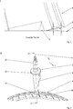
Gemäß
Die Leitschaufeln
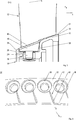
Wie im Schnitt G-G nach
Der Innenring
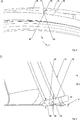
Wie in
Gemäß
Wie deutlich in
Wie in
Offenbart ist ein Leitschaufelkranz für eine Strömungsmaschine, mit einer Vielzahl von Leitschaufeln, die jeweils um ihre Hauptachse verstellbar sind, und mit einem Innenring zum radial inneren Stabilisieren der Leitschaufeln, wobei eine Ringfläche des Innenrings und/oder jeweils eine der Ringfläche zugewandte und von dieser radial beabstandete Schaufelendfläche der Leitschaufeln in einem Winkel ungleich 90° zur Hauptachse orientiert ist/sind, wobei in die Ringfläche im Verstellbereich jeder Leitschaufel eine längliche Vertiefung eingebracht ist, die mit der jeweils gegenüberliegenden Schaufelendfläche über einen Teil des Verstellbereichs der Leitschaufel einen konstanten Radialspalt bildet, eine Strömungsmaschine sowie ein Innenring.Disclosed is a vane ring for a turbomachine, with a plurality of vanes, which are each adjustable about its main axis, and with an inner ring for radially inner stabilizing the guide vanes, wherein an annular surface of the inner ring and / or each one of the annular surface facing and radially thereof spaced blade end surface of the vanes is / are oriented at an angle not equal to 90 ° to the main axis, wherein in the annular surface in the adjustment of each vane an elongated recess is formed which forms a constant radial gap with the respective opposite blade end over a portion of the adjustment of the vane Turbomachine and an inner ring.
BezugszeichenlisteLIST OF REFERENCE NUMBERS
- 11
- Leitschaufelkranz vane ring
- 22
- Innenring inner ring
- 44
- Leitschaufel vane
- 66
- Abflachung flattening
- 88th
- Schaufelendfläche Blade end surface
- 1010
- Leitschaufelkranz vane ring
- 1212
- Leitschaufel vane
- 1414
- Innenring inner ring
- 1616
- Schaufelblatt airfoil
- 1818
- innerer Schaufelteller inner shovel plate
- 2020
- äußerer Schaufelteller outer shovel plate
- 2222
- Verstellzapfen adjustment peg
- 2424
- Lagerzapfen pivot
- 2626
- Lagerbohrung bearing bore
- 2828
- Lagerbuchse bearing bush
- 30 30
- Schaufelendfläche Blade end surface
- 3232
- Ringfläche ring surface
- 3434
- Vorderkante leading edge
- 3636
- Hinterkante trailing edge
- 3838
- Erweiterung extension
- 4040
- Tellerfläche plate surface
- 4242
- Vertiefung deepening
- 4444
- Grund reason
- 4646
- steile Flanke steep flank
- 4848
- flache Flanke flat flank
- 5050
- Verengung narrowing
- 5252
- Radialspalt radial gap
- aa
- Abstand distance
- bb
- Abstand distance
- hH
- Hauptachse/Schaufelachse Major axis / blade axis
- xx
- Strömungsrichtung/Kranzlängsachse Flow direction / longitudinal axis Kranz
- zz
- Radialrichtung radial direction
ZITATE ENTHALTEN IN DER BESCHREIBUNG QUOTES INCLUDE IN THE DESCRIPTION
Diese Liste der vom Anmelder aufgeführten Dokumente wurde automatisiert erzeugt und ist ausschließlich zur besseren Information des Lesers aufgenommen. Die Liste ist nicht Bestandteil der deutschen Patent- bzw. Gebrauchsmusteranmeldung. Das DPMA übernimmt keinerlei Haftung für etwaige Fehler oder Auslassungen.This list of the documents listed by the applicant has been generated automatically and is included solely for the better information of the reader. The list is not part of the German patent or utility model application. The DPMA assumes no liability for any errors or omissions.
Zitierte PatentliteraturCited patent literature
- US 7802963 B3 [0004] US 7802963 B3 [0004]
Claims (8)
Priority Applications (1)
| Application Number | Priority Date | Filing Date | Title |
|---|---|---|---|
| DE102012220249.8A DE102012220249B4 (en) | 2012-11-07 | 2012-11-07 | Guide vane, turbomachine and inner ring |
Applications Claiming Priority (1)
| Application Number | Priority Date | Filing Date | Title |
|---|---|---|---|
| DE102012220249.8A DE102012220249B4 (en) | 2012-11-07 | 2012-11-07 | Guide vane, turbomachine and inner ring |
Publications (2)
| Publication Number | Publication Date |
|---|---|
| DE102012220249A1 true DE102012220249A1 (en) | 2014-05-08 |
| DE102012220249B4 DE102012220249B4 (en) | 2017-08-17 |
Family
ID=50489795
Family Applications (1)
| Application Number | Title | Priority Date | Filing Date |
|---|---|---|---|
| DE102012220249.8A Expired - Fee Related DE102012220249B4 (en) | 2012-11-07 | 2012-11-07 | Guide vane, turbomachine and inner ring |
Country Status (1)
| Country | Link |
|---|---|
| DE (1) | DE102012220249B4 (en) |
Cited By (4)
| Publication number | Priority date | Publication date | Assignee | Title |
|---|---|---|---|---|
| US20170268356A1 (en) * | 2016-03-16 | 2017-09-21 | MTU Aero Engines AG | Guide vane plate with a chamfered and a cylindrical edge region |
| DE102018203442A1 (en) * | 2018-03-07 | 2019-09-12 | MTU Aero Engines AG | Inner ring for a turbomachine, vane ring with an inner ring, turbomachinery and method of making an inner ring |
| CN114876838A (en) * | 2021-02-05 | 2022-08-09 | 中国航发商用航空发动机有限责任公司 | Blade tip clearance adjusting structure for adjustable stationary blade of impeller and gas compressor using same |
| DE102021129033A1 (en) | 2021-11-08 | 2023-05-11 | MTU Aero Engines AG | Adjustable guide vane with a convex, radially inner bearing section for a gas turbine, in particular an aircraft gas turbine |
Citations (3)
| Publication number | Priority date | Publication date | Assignee | Title |
|---|---|---|---|---|
| US20020061249A1 (en) * | 2000-09-18 | 2002-05-23 | Snecma Moteurs | Compressor stator having a constant clearance |
| DE10352787A1 (en) * | 2003-11-12 | 2005-06-23 | Mtu Aero Engines Gmbh | Guide vane grille and turbomachine with a vane grille |
| US7802963B2 (en) | 2005-03-05 | 2010-09-28 | Rolls-Royce Plc | Pivot ring |
-
2012
- 2012-11-07 DE DE102012220249.8A patent/DE102012220249B4/en not_active Expired - Fee Related
Patent Citations (3)
| Publication number | Priority date | Publication date | Assignee | Title |
|---|---|---|---|---|
| US20020061249A1 (en) * | 2000-09-18 | 2002-05-23 | Snecma Moteurs | Compressor stator having a constant clearance |
| DE10352787A1 (en) * | 2003-11-12 | 2005-06-23 | Mtu Aero Engines Gmbh | Guide vane grille and turbomachine with a vane grille |
| US7802963B2 (en) | 2005-03-05 | 2010-09-28 | Rolls-Royce Plc | Pivot ring |
Cited By (8)
| Publication number | Priority date | Publication date | Assignee | Title |
|---|---|---|---|---|
| US20170268356A1 (en) * | 2016-03-16 | 2017-09-21 | MTU Aero Engines AG | Guide vane plate with a chamfered and a cylindrical edge region |
| US11162376B2 (en) * | 2016-03-16 | 2021-11-02 | MTU Aero Engines AG | Guide vane plate with a chamfered and a cylindrical edge region |
| DE102018203442A1 (en) * | 2018-03-07 | 2019-09-12 | MTU Aero Engines AG | Inner ring for a turbomachine, vane ring with an inner ring, turbomachinery and method of making an inner ring |
| US11098603B2 (en) | 2018-03-07 | 2021-08-24 | MTU Aero Engines AG | Inner ring for a turbomachine, vane ring with an inner ring, turbomachine and method of making an inner ring |
| CN114876838A (en) * | 2021-02-05 | 2022-08-09 | 中国航发商用航空发动机有限责任公司 | Blade tip clearance adjusting structure for adjustable stationary blade of impeller and gas compressor using same |
| CN114876838B (en) * | 2021-02-05 | 2023-08-18 | 中国航发商用航空发动机有限责任公司 | Blade tip gap adjusting structure for impeller adjustable stationary blade and impeller and compressor using same |
| DE102021129033A1 (en) | 2021-11-08 | 2023-05-11 | MTU Aero Engines AG | Adjustable guide vane with a convex, radially inner bearing section for a gas turbine, in particular an aircraft gas turbine |
| US11892012B2 (en) | 2021-11-08 | 2024-02-06 | MTU Aero Engines AG | Adjustable guide vane with convexly shaped, radially inner storage section for a gas turbine, in particular an aircraft gas turbine |
Also Published As
| Publication number | Publication date |
|---|---|
| DE102012220249B4 (en) | 2017-08-17 |
Similar Documents
| Publication | Publication Date | Title |
|---|---|---|
| EP2696029B1 (en) | Blade row with side wall contours and fluid flow engine | |
| DE102011055150B4 (en) | Turbine blade arrangement | |
| EP2927503B1 (en) | Gas turbine compressor, aircraft engine and design method | |
| EP3032037B1 (en) | Guide vane assembly and turbo machine | |
| EP2692986B1 (en) | Blade row with side wall contours and fluid flow engine | |
| CH704105B1 (en) | Multistage gas turbine. | |
| DE102007020025A1 (en) | Shape of a gas channel in an axial flow gas turbine engine | |
| EP2746533A1 (en) | Blade grid and turbomachine | |
| EP2558685B1 (en) | Guide vane | |
| DE102015224283A1 (en) | Guide vane cluster for a turbomachine | |
| EP2626512A1 (en) | Flow engine | |
| DE102015224376A1 (en) | Bucket channel, blade grid and turbomachine | |
| EP2806103B1 (en) | Cascade and turbo-engine | |
| DE102012220249B4 (en) | Guide vane, turbomachine and inner ring | |
| WO2005116404A1 (en) | Vane comprising a transition zone | |
| DE102014219058A1 (en) | Radial compressor impeller and associated centrifugal compressor | |
| DE102010031213A1 (en) | Rotor of a turbomachine | |
| DE102009007664A1 (en) | Sealing device on the blade shank of a rotor stage of an axial flow machine | |
| EP3388626A1 (en) | Contouring of a blade row platform | |
| EP2963243B1 (en) | Flow engine with blades having blade tips lowering towards the trailing edge | |
| DE102013220276A1 (en) | flow machine | |
| EP2650475A1 (en) | Blade for a flow device, blade assembly and flow device | |
| EP2530330B1 (en) | Rotor blade for the compressor of a turbo engine, compressor and turbo machine | |
| EP3428391A1 (en) | Blade grid of a turbomachine | |
| EP3404211A1 (en) | Blade cascade segment for a turbine with contoured platform surface, corresponding blade cascade, blade channel, platform, turbine and aircraft engine |
Legal Events
| Date | Code | Title | Description |
|---|---|---|---|
| R012 | Request for examination validly filed | ||
| R016 | Response to examination communication | ||
| R016 | Response to examination communication | ||
| R018 | Grant decision by examination section/examining division | ||
| R020 | Patent grant now final | ||
| R119 | Application deemed withdrawn, or ip right lapsed, due to non-payment of renewal fee |