DE102012203712A1 - Cable termination - Google Patents
Cable termination Download PDFInfo
- Publication number
- DE102012203712A1 DE102012203712A1 DE102012203712A DE102012203712A DE102012203712A1 DE 102012203712 A1 DE102012203712 A1 DE 102012203712A1 DE 102012203712 A DE102012203712 A DE 102012203712A DE 102012203712 A DE102012203712 A DE 102012203712A DE 102012203712 A1 DE102012203712 A1 DE 102012203712A1
- Authority
- DE
- Germany
- Prior art keywords
- cable
- cable end
- cable termination
- insulating body
- support flange
- Prior art date
- Legal status (The legal status is an assumption and is not a legal conclusion. Google has not performed a legal analysis and makes no representation as to the accuracy of the status listed.)
- Ceased
Links
Images
Classifications
-
- H—ELECTRICITY
- H01—ELECTRIC ELEMENTS
- H01R—ELECTRICALLY-CONDUCTIVE CONNECTIONS; STRUCTURAL ASSOCIATIONS OF A PLURALITY OF MUTUALLY-INSULATED ELECTRICAL CONNECTING ELEMENTS; COUPLING DEVICES; CURRENT COLLECTORS
- H01R3/00—Electrically-conductive connections not otherwise provided for
-
- H—ELECTRICITY
- H02—GENERATION; CONVERSION OR DISTRIBUTION OF ELECTRIC POWER
- H02G—INSTALLATION OF ELECTRIC CABLES OR LINES, OR OF COMBINED OPTICAL AND ELECTRIC CABLES OR LINES
- H02G15/00—Cable fittings
- H02G15/02—Cable terminations
- H02G15/06—Cable terminating boxes, frames or other structures
- H02G15/064—Cable terminating boxes, frames or other structures with devices for relieving electrical stress
Abstract
Die Erfindung betrifft einen Kabelendverschluss (1) mit einem äußeren Isolator (7), der sich einerseits auf einem kabelseitigen Tragflansch (5) abstützt und andererseits einen Freiluftanschluss (3) trägt, wobei im Tragflansch (5) eine Öffnung (9) mit einem Isolierkörper (10) zum Einführen eines Kabelendes (2) vorhanden ist. Um einen solchen Kabelendverschluss einfach im Aufbau und leicht montierbar zu gestalten, ist erfindungsgemäß sein Isolierkörper eine gesteuerte Hochspannungsdurchführung (10) mit einem von außen zugänglichen, zentralen Steckkontakt (16).The invention relates to a cable end closure (1) with an outer insulator (7) which is supported on the one hand on a cable side support flange (5) and on the other hand carries an open air connection (3), wherein in the support flange (5) has an opening (9) with an insulating body (10) for inserting a cable end (2) is present. To make such a cable termination simple in construction and easy to install, according to the invention, its insulating body is a controlled high-voltage bushing (10) with an externally accessible, central plug contact (16).
Description
Die Erfindung betrifft einen Kabelendverschluss mit einem äußeren Isolator, der sich einerseits auf einem kabelseitigen Tragflansch abstützt und andererseits einen Freiluftanschluss trägt, wobei im Tragflansch eine Öffnung mit einem Isolierkörper zum Einführen eines Kabelendes vorhanden ist. The invention relates to a cable end closure with an outer insulator, which is supported on the one hand on a cable-side support flange and on the other hand carries an outdoor connection, wherein in the support flange, an opening with an insulating body for inserting a cable end is present.
Bei einem bekannten Kabelendverschluss dieser Art (Vorlesungsskript von
Der Erfindung liegt die Aufgabe zugrunde, einen solchen Kabelendverschluss so auszugestalten, dass er einen einfachen Aufbau hat und einfach zu montieren ist. The invention has the object of providing such a cable end closure in such a way that it has a simple structure and is easy to assemble.
Zur Lösung dieser Aufgabe ist bei einem Kabelendverschluss der eingangs angegebenen Art erfindungsgemäß der Isolierkörper eine gesteuerte Hochspannungsdurchführung mit einem von außen zugänglichen, zentralen Steckkontakt. To solve this problem is in a cable termination of the type specified according to the invention, the insulator a controlled high-voltage bushing with an externally accessible, central plug contact.
Ein wesentlicher Vorteil des erfindungsgemäßen Kabelendverschlusses besteht darin, dass ein vorkonfektioniertes Kabelende ohne weiteres in die gesteuerte Hochspannungsdurchführung eingebracht werden kann; der Kabelendverschluss selbst braucht dazu nicht geöffnet zu werden. Ein weiterer Vorteil wird darin gesehen, dass die leitenden Einlagen der gesteuerten Hochspannungsdurchführung eine gute freiluftseitige Feldsteuerung übernehmen. An essential advantage of the cable end closure according to the invention is that a prefabricated cable end can be easily introduced into the controlled high-voltage feedthrough; the cable end itself does not need to be opened. Another advantage is seen in the fact that the conductive deposits of the controlled high-voltage bushing take over a good open-air field control.
Dies gilt insbesondere dann, wenn der erfindungsgemäße Kabelendverschluss mindestens an seinem von dem äußeren Isolator abgewandten einen Ende eine sich zu diesem Ende hin öffnende, innere kegelförmige Ausnehmung zur Aufnahme des entsprechend geformten Kabelendes aufweist. This applies in particular when the cable end closure according to the invention has at least at its end facing away from the outer insulator one end which opens towards this end, inner conical recess for receiving the correspondingly shaped cable end.
Bei einer vorteilhaften Ausführungsform des erfindungsgemäßen Kabelendverschlusses ist Ausnehmung der Hochspannungsdurchführung entsprechend einem Kabelende mit einer aufgeschobenen Erdelektrode und einem isolierenden Konus geformt. Damit ist eine optimale Feldsteuerung erreichbar. In an advantageous embodiment of the cable end closure according to the invention, the recess of the high-voltage feedthrough is shaped corresponding to a cable end with a pushed-on earth electrode and an insulating cone. This achieves optimum field control.
Als Werkstoff für die Isolierung der Hochspannungsdurchführung des erfindungsgemäßen Kabelendverschlusses kommen verschiedene Isoliermaterialien in Frage, beispielsweise Gießharz. Als besonders vorteilhaft wird es jedoch angesehen, wenn die Isolierung der Hochspannungsdurchführung aus harzimprägnierten Papier besteht, weil sich damit eine besonders feinstufige Feldsteuerung durch besonders dicht voneinander beabstandete Steuereinlagen erzielen lässt. As a material for the insulation of the high voltage feedthrough of the cable end closure according to the invention various insulating materials are suitable, for example cast resin. However, it is considered to be particularly advantageous if the insulation of the high-voltage leadthrough consists of resin-impregnated paper, because this allows a particularly fine-scale field control to be achieved by control inserts which are particularly closely spaced from each other.
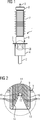
Zur weiteren Erläuterung der Erfindung ist in For further explanation of the invention is in
In der
Wie
Ist das Schutzgehäuse
Die Isolierung der Hochspannungsdurchführung
ZITATE ENTHALTEN IN DER BESCHREIBUNG QUOTES INCLUDE IN THE DESCRIPTION
Diese Liste der vom Anmelder aufgeführten Dokumente wurde automatisiert erzeugt und ist ausschließlich zur besseren Information des Lesers aufgenommen. Die Liste ist nicht Bestandteil der deutschen Patent- bzw. Gebrauchsmusteranmeldung. Das DPMA übernimmt keinerlei Haftung für etwaige Fehler oder Auslassungen.This list of the documents listed by the applicant has been generated automatically and is included solely for the better information of the reader. The list is not part of the German patent or utility model application. The DPMA assumes no liability for any errors or omissions.
Zitierte Nicht-PatentliteraturCited non-patent literature
- Prof. Volker Hinrichsen, “Hochspannungstechnik“ WS 10/11 + SS 11, Seite 22 [0002] Prof. Volker Hinrichsen, "High Voltage Technology" WS 10/11 + SS 11, page 22 [0002]
Claims (4)
Priority Applications (3)
| Application Number | Priority Date | Filing Date | Title |
|---|---|---|---|
| DE102012203712A DE102012203712A1 (en) | 2012-03-08 | 2012-03-08 | Cable termination |
| CA2808951A CA2808951A1 (en) | 2012-03-08 | 2013-03-07 | Cable end termination |
| US13/790,366 US20130233617A1 (en) | 2012-03-08 | 2013-03-08 | Cable end termination |
Applications Claiming Priority (1)
| Application Number | Priority Date | Filing Date | Title |
|---|---|---|---|
| DE102012203712A DE102012203712A1 (en) | 2012-03-08 | 2012-03-08 | Cable termination |
Publications (1)
| Publication Number | Publication Date |
|---|---|
| DE102012203712A1 true DE102012203712A1 (en) | 2013-09-12 |
Family
ID=49029592
Family Applications (1)
| Application Number | Title | Priority Date | Filing Date |
|---|---|---|---|
| DE102012203712A Ceased DE102012203712A1 (en) | 2012-03-08 | 2012-03-08 | Cable termination |
Country Status (3)
| Country | Link |
|---|---|
| US (1) | US20130233617A1 (en) |
| CA (1) | CA2808951A1 (en) |
| DE (1) | DE102012203712A1 (en) |
Cited By (7)
| Publication number | Priority date | Publication date | Assignee | Title |
|---|---|---|---|---|
| WO2017089023A1 (en) | 2015-11-27 | 2017-06-01 | Siemens Aktiengesellschaft | High-voltage device |
| EP3358690A1 (en) * | 2017-02-07 | 2018-08-08 | NKT GmbH & Co. KG | Coupling sleeve |
| DE102017212977A1 (en) * | 2017-07-27 | 2019-01-31 | Siemens Aktiengesellschaft | Plug-in high-voltage bushing and electrical device with the plug-in high-voltage bushing |
| DE102018201160A1 (en) * | 2018-01-25 | 2019-07-25 | Pfisterer Kontaktsysteme Gmbh | High voltage bushing, electrical device with high voltage bushing and method of manufacturing the electrical device |
| DE102018116399A1 (en) * | 2018-07-06 | 2020-01-09 | Nkt Gmbh & Co. Kg | coupling sleeve |
| DE102018116416A1 (en) * | 2018-07-06 | 2020-01-09 | Nkt Gmbh & Co. Kg | coupling sleeve |
| DE102022205033A1 (en) | 2022-05-20 | 2023-11-23 | Siemens Energy Global GmbH & Co. KG | High-voltage device and method for producing same |
Families Citing this family (1)
| Publication number | Priority date | Publication date | Assignee | Title |
|---|---|---|---|---|
| US11146053B2 (en) * | 2016-01-29 | 2021-10-12 | Power Hv Inc. | Bushing for a transformer |
Citations (4)
| Publication number | Priority date | Publication date | Assignee | Title |
|---|---|---|---|---|
| DE4224672C1 (en) * | 1992-07-25 | 1993-09-09 | Karl Pfisterer Elektrotechnische Spezialartikel Gmbh & Co Kg, 7000 Stuttgart, De | |
| DE19702875A1 (en) * | 1997-01-28 | 1998-09-17 | Sachsenwerk Ag | Voltage converter |
| DE19940361A1 (en) * | 1999-08-25 | 2001-03-01 | Abb Patent Gmbh | Power cable sealing end for cable connection, has slide valve and/or high voltage electrode made of aluminium foam |
| DE19945148A1 (en) * | 1999-09-21 | 2001-03-22 | Detlef Jegust | End closure unit for high-voltage electric cables comprises a socket which in the insulator body is at least partially embedded in a solid insulating element and has an opening for entry of the cable plug |
Family Cites Families (4)
| Publication number | Priority date | Publication date | Assignee | Title |
|---|---|---|---|---|
| JP3744876B2 (en) * | 2002-04-08 | 2006-02-15 | 昭和電線電纜株式会社 | Polymer sleeve and cable termination connection using the same |
| JP4195848B2 (en) * | 2003-10-08 | 2008-12-17 | 昭和電線ケーブルシステム株式会社 | Air end polymer sleeve and cable air end connection using the same |
| FR2883425B1 (en) * | 2005-03-21 | 2007-05-04 | Nexans Sa | SYNTHETIC END OF ELECTRIC CABLE FOR CONTINUOUS VOLTAGE |
| EP2264719B1 (en) * | 2009-06-18 | 2014-04-02 | ABB Technology Ltd | High voltage device |
-
2012
- 2012-03-08 DE DE102012203712A patent/DE102012203712A1/en not_active Ceased
-
2013
- 2013-03-07 CA CA2808951A patent/CA2808951A1/en not_active Abandoned
- 2013-03-08 US US13/790,366 patent/US20130233617A1/en not_active Abandoned
Patent Citations (4)
| Publication number | Priority date | Publication date | Assignee | Title |
|---|---|---|---|---|
| DE4224672C1 (en) * | 1992-07-25 | 1993-09-09 | Karl Pfisterer Elektrotechnische Spezialartikel Gmbh & Co Kg, 7000 Stuttgart, De | |
| DE19702875A1 (en) * | 1997-01-28 | 1998-09-17 | Sachsenwerk Ag | Voltage converter |
| DE19940361A1 (en) * | 1999-08-25 | 2001-03-01 | Abb Patent Gmbh | Power cable sealing end for cable connection, has slide valve and/or high voltage electrode made of aluminium foam |
| DE19945148A1 (en) * | 1999-09-21 | 2001-03-22 | Detlef Jegust | End closure unit for high-voltage electric cables comprises a socket which in the insulator body is at least partially embedded in a solid insulating element and has an opening for entry of the cable plug |
Non-Patent Citations (1)
| Title |
|---|
| Prof. Volker Hinrichsen, "Hochspannungstechnik" WS 10/11 + SS 11, Seite 22 |
Cited By (12)
| Publication number | Priority date | Publication date | Assignee | Title |
|---|---|---|---|---|
| WO2017089023A1 (en) | 2015-11-27 | 2017-06-01 | Siemens Aktiengesellschaft | High-voltage device |
| DE102015223587A1 (en) | 2015-11-27 | 2017-06-01 | Siemens Aktiengesellschaft | High voltage device |
| EP3358690A1 (en) * | 2017-02-07 | 2018-08-08 | NKT GmbH & Co. KG | Coupling sleeve |
| DE102017102370A1 (en) | 2017-02-07 | 2018-08-09 | nkt cables GmbH & Co.KG | coupling sleeve |
| DE102017212977A1 (en) * | 2017-07-27 | 2019-01-31 | Siemens Aktiengesellschaft | Plug-in high-voltage bushing and electrical device with the plug-in high-voltage bushing |
| US11469014B2 (en) | 2017-07-27 | 2022-10-11 | Siemens Energy Global GmbH & Co. KG | Electrical device having an insertable high-voltage bushing |
| DE102018201160A1 (en) * | 2018-01-25 | 2019-07-25 | Pfisterer Kontaktsysteme Gmbh | High voltage bushing, electrical device with high voltage bushing and method of manufacturing the electrical device |
| US11295876B2 (en) | 2018-01-25 | 2022-04-05 | Siemens Energy Global GmbH & Co. KG | High-voltage feed-through, electrical device having a high-voltage feed-through, and method for producing the electrical device |
| DE102018116399A1 (en) * | 2018-07-06 | 2020-01-09 | Nkt Gmbh & Co. Kg | coupling sleeve |
| DE102018116416A1 (en) * | 2018-07-06 | 2020-01-09 | Nkt Gmbh & Co. Kg | coupling sleeve |
| US11502499B2 (en) | 2018-07-06 | 2022-11-15 | Nkt Gmbh & Co. Kg | Coupling sleeve |
| DE102022205033A1 (en) | 2022-05-20 | 2023-11-23 | Siemens Energy Global GmbH & Co. KG | High-voltage device and method for producing same |
Also Published As
| Publication number | Publication date |
|---|---|
| CA2808951A1 (en) | 2013-09-08 |
| US20130233617A1 (en) | 2013-09-12 |
Similar Documents
| Publication | Publication Date | Title |
|---|---|---|
| DE102012203712A1 (en) | Cable termination | |
| DE102006036233B4 (en) | Outdoor termination | |
| EP3229242B1 (en) | High voltage feed-through | |
| DE102012204052A1 (en) | High voltage bushing with conductive inserts for DC voltage and process for their manufacture | |
| DE102012217310A1 (en) | Surge arresters | |
| DE112010005301T5 (en) | POWER SWITCHING | |
| DE102007003636A1 (en) | Insulating body for a busbar coupling and busbar coupling | |
| WO2017186751A1 (en) | Transformer with insertable high-voltage bushings | |
| DE102013211133A1 (en) | Isolation system and mounting method of an insulation system | |
| EP2669903B1 (en) | Enclosed surge absorber with central feedthrough | |
| DE202010005735U1 (en) | Connector for stranded conductor | |
| DE102010005086A1 (en) | High-voltage bushing | |
| DE102012203709B4 (en) | High-voltage feedthrough for direct voltage | |
| DE102016214408A1 (en) | insulator | |
| EP3048617B1 (en) | Surge absorber | |
| DE3300901A1 (en) | Cast-resin insulator for high-voltage cable end closures | |
| DE3420500A1 (en) | XLPE-insulated very-high-voltage cable with end closure | |
| EP3082136B1 (en) | Gas-insulated surge arrestor | |
| DE202014103232U1 (en) | Kabelendgarnitur | |
| DE683018C (en) | Single-wire current transformer with two-part bushing insulator | |
| DE102016112096A1 (en) | EXECUTION | |
| DE3014601A1 (en) | FITTING FOR THE PRODUCTION OF A CONNECTION WITH A HIGH TENSILE STRENGTH WITH A GLASS FIBER REINFORCED PLASTIC ROD | |
| EP3323180B1 (en) | Gasinsulated electrical module | |
| WO2019025023A1 (en) | Insertable feed-through | |
| DE102016209132A1 (en) | Device for connecting a high voltage conductor to a winding of an electrical device |
Legal Events
| Date | Code | Title | Description |
|---|---|---|---|
| R012 | Request for examination validly filed | ||
| R016 | Response to examination communication | ||
| R002 | Refusal decision in examination/registration proceedings | ||
| R003 | Refusal decision now final |
Effective date: 20131030 |