DE102012201601A1 - Method for controlling an internal combustion engine - Google Patents
Method for controlling an internal combustion engine Download PDFInfo
- Publication number
- DE102012201601A1 DE102012201601A1 DE102012201601A DE102012201601A DE102012201601A1 DE 102012201601 A1 DE102012201601 A1 DE 102012201601A1 DE 102012201601 A DE102012201601 A DE 102012201601A DE 102012201601 A DE102012201601 A DE 102012201601A DE 102012201601 A1 DE102012201601 A1 DE 102012201601A1
- Authority
- DE
- Germany
- Prior art keywords
- injector
- cylinder
- internal combustion
- combustion engine
- determined
- Prior art date
- Legal status (The legal status is an assumption and is not a legal conclusion. Google has not performed a legal analysis and makes no representation as to the accuracy of the status listed.)
- Withdrawn
Links
Images


Classifications
-
- F—MECHANICAL ENGINEERING; LIGHTING; HEATING; WEAPONS; BLASTING
- F02—COMBUSTION ENGINES; HOT-GAS OR COMBUSTION-PRODUCT ENGINE PLANTS
- F02D—CONTROLLING COMBUSTION ENGINES
- F02D41/00—Electrical control of supply of combustible mixture or its constituents
- F02D41/30—Controlling fuel injection
- F02D41/38—Controlling fuel injection of the high pressure type
- F02D41/40—Controlling fuel injection of the high pressure type with means for controlling injection timing or duration
-
- F—MECHANICAL ENGINEERING; LIGHTING; HEATING; WEAPONS; BLASTING
- F02—COMBUSTION ENGINES; HOT-GAS OR COMBUSTION-PRODUCT ENGINE PLANTS
- F02D—CONTROLLING COMBUSTION ENGINES
- F02D41/00—Electrical control of supply of combustible mixture or its constituents
- F02D41/24—Electrical control of supply of combustible mixture or its constituents characterised by the use of digital means
- F02D41/2406—Electrical control of supply of combustible mixture or its constituents characterised by the use of digital means using essentially read only memories
- F02D41/2425—Particular ways of programming the data
- F02D41/2429—Methods of calibrating or learning
- F02D41/2438—Active learning methods
-
- F—MECHANICAL ENGINEERING; LIGHTING; HEATING; WEAPONS; BLASTING
- F02—COMBUSTION ENGINES; HOT-GAS OR COMBUSTION-PRODUCT ENGINE PLANTS
- F02D—CONTROLLING COMBUSTION ENGINES
- F02D35/00—Controlling engines, dependent on conditions exterior or interior to engines, not otherwise provided for
- F02D35/02—Controlling engines, dependent on conditions exterior or interior to engines, not otherwise provided for on interior conditions
- F02D35/023—Controlling engines, dependent on conditions exterior or interior to engines, not otherwise provided for on interior conditions by determining the cylinder pressure
-
- F—MECHANICAL ENGINEERING; LIGHTING; HEATING; WEAPONS; BLASTING
- F02—COMBUSTION ENGINES; HOT-GAS OR COMBUSTION-PRODUCT ENGINE PLANTS
- F02D—CONTROLLING COMBUSTION ENGINES
- F02D41/00—Electrical control of supply of combustible mixture or its constituents
- F02D41/24—Electrical control of supply of combustible mixture or its constituents characterised by the use of digital means
- F02D41/2406—Electrical control of supply of combustible mixture or its constituents characterised by the use of digital means using essentially read only memories
- F02D41/2425—Particular ways of programming the data
- F02D41/2429—Methods of calibrating or learning
- F02D41/2451—Methods of calibrating or learning characterised by what is learned or calibrated
- F02D41/2464—Characteristics of actuators
- F02D41/2467—Characteristics of actuators for injectors
-
- F—MECHANICAL ENGINEERING; LIGHTING; HEATING; WEAPONS; BLASTING
- F02—COMBUSTION ENGINES; HOT-GAS OR COMBUSTION-PRODUCT ENGINE PLANTS
- F02D—CONTROLLING COMBUSTION ENGINES
- F02D2200/00—Input parameters for engine control
- F02D2200/02—Input parameters for engine control the parameters being related to the engine
- F02D2200/06—Fuel or fuel supply system parameters
- F02D2200/0614—Actual fuel mass or fuel injection amount
- F02D2200/0616—Actual fuel mass or fuel injection amount determined by estimation
-
- F—MECHANICAL ENGINEERING; LIGHTING; HEATING; WEAPONS; BLASTING
- F02—COMBUSTION ENGINES; HOT-GAS OR COMBUSTION-PRODUCT ENGINE PLANTS
- F02D—CONTROLLING COMBUSTION ENGINES
- F02D2200/00—Input parameters for engine control
- F02D2200/02—Input parameters for engine control the parameters being related to the engine
- F02D2200/10—Parameters related to the engine output, e.g. engine torque or engine speed
- F02D2200/1015—Engines misfires
-
- F—MECHANICAL ENGINEERING; LIGHTING; HEATING; WEAPONS; BLASTING
- F02—COMBUSTION ENGINES; HOT-GAS OR COMBUSTION-PRODUCT ENGINE PLANTS
- F02D—CONTROLLING COMBUSTION ENGINES
- F02D41/00—Electrical control of supply of combustible mixture or its constituents
- F02D41/02—Circuit arrangements for generating control signals
- F02D41/04—Introducing corrections for particular operating conditions
- F02D41/042—Introducing corrections for particular operating conditions for stopping the engine
-
- F—MECHANICAL ENGINEERING; LIGHTING; HEATING; WEAPONS; BLASTING
- F02—COMBUSTION ENGINES; HOT-GAS OR COMBUSTION-PRODUCT ENGINE PLANTS
- F02D—CONTROLLING COMBUSTION ENGINES
- F02D41/00—Electrical control of supply of combustible mixture or its constituents
- F02D41/02—Circuit arrangements for generating control signals
- F02D41/04—Introducing corrections for particular operating conditions
- F02D41/06—Introducing corrections for particular operating conditions for engine starting or warming up
-
- F—MECHANICAL ENGINEERING; LIGHTING; HEATING; WEAPONS; BLASTING
- F02—COMBUSTION ENGINES; HOT-GAS OR COMBUSTION-PRODUCT ENGINE PLANTS
- F02D—CONTROLLING COMBUSTION ENGINES
- F02D41/00—Electrical control of supply of combustible mixture or its constituents
- F02D41/02—Circuit arrangements for generating control signals
- F02D41/14—Introducing closed-loop corrections
- F02D41/1438—Introducing closed-loop corrections using means for determining characteristics of the combustion gases; Sensors therefor
- F02D41/1444—Introducing closed-loop corrections using means for determining characteristics of the combustion gases; Sensors therefor characterised by the characteristics of the combustion gases
- F02D41/1454—Introducing closed-loop corrections using means for determining characteristics of the combustion gases; Sensors therefor characterised by the characteristics of the combustion gases the characteristics being an oxygen content or concentration or the air-fuel ratio
-
- F—MECHANICAL ENGINEERING; LIGHTING; HEATING; WEAPONS; BLASTING
- F02—COMBUSTION ENGINES; HOT-GAS OR COMBUSTION-PRODUCT ENGINE PLANTS
- F02D—CONTROLLING COMBUSTION ENGINES
- F02D41/00—Electrical control of supply of combustible mixture or its constituents
- F02D41/02—Circuit arrangements for generating control signals
- F02D41/14—Introducing closed-loop corrections
- F02D41/1497—With detection of the mechanical response of the engine
- F02D41/1498—With detection of the mechanical response of the engine measuring engine roughness
-
- F—MECHANICAL ENGINEERING; LIGHTING; HEATING; WEAPONS; BLASTING
- F02—COMBUSTION ENGINES; HOT-GAS OR COMBUSTION-PRODUCT ENGINE PLANTS
- F02D—CONTROLLING COMBUSTION ENGINES
- F02D41/00—Electrical control of supply of combustible mixture or its constituents
- F02D41/24—Electrical control of supply of combustible mixture or its constituents characterised by the use of digital means
- F02D41/2406—Electrical control of supply of combustible mixture or its constituents characterised by the use of digital means using essentially read only memories
- F02D41/2425—Particular ways of programming the data
- F02D41/2429—Methods of calibrating or learning
- F02D41/2451—Methods of calibrating or learning characterised by what is learned or calibrated
- F02D41/2464—Characteristics of actuators
- F02D41/2467—Characteristics of actuators for injectors
- F02D41/247—Behaviour for small quantities
Abstract
Verfahren zur Steuerung einer Brennkraftmaschine (10) umfassend folgende Schritte: – mittels des Drucksensorverfahrens wird in einem ersten Schritt (40) für einen ersten Injektor (20d) eine erste Ansteuerdauer (tvorL) ermittelt, bei der eine gewünschte Kraftstoffmenge in einen ersten Zylinder (12d) eingespritzt wird. Die erste Ansteuerdauer (tvorL) wird in einem Steuer- und/oder Regelgerät (38) nichtflüchtig gespeichert; – in einem zweiten Schritt (42) wird der erste Injektor (20d) mit der ersten Ansteuerdauer (tvorL) angesteuert und ein daraus resultierendes Mengenersatzsignal wird in Abhängigkeit der Triebstrangparameter in einem Lernkennfeld abgelegt und nichtflüchtig im Steuer- und/oder Regelgerät (38) gespeichert; – in einem dritten Schritt (44) wird mittels der Nullmengenkalibrierung für alle weiteren Zylinder (20) eine Ansteuerdauer der den Zylindern (20) zugeordneten Injektoren (12) variiert, bis das im zweiten Schritt (42) ermittelte Mengenersatzsignal als Sollwert erreicht ist wobei die so ermittelte Ansteuerdauer nichtflüchtig im Steuer- und/oder Regelgerät (38) gespeichert wird.Method for controlling an internal combustion engine (10) comprising the following steps: - a first activation time (tvorL) is determined by means of the pressure sensor method in a first step (40) for a first injector (20d), in which a desired amount of fuel in a first cylinder (12d ) is injected. The first activation duration (tvorL) is stored non-volatilely in a control and / or regulating device (38); - In a second step (42), the first injector (20d) with the first drive time (tvorL) is driven and a resulting quantity replacement signal is stored as a function of the drive train parameters in a learning map and stored non-volatile in the control and / or regulating device (38) ; In a third step (44), a control duration of the injectors (12) assigned to the cylinders (20) is varied by means of the zero quantity calibration for all further cylinders (20) until the quantity replacement signal ascertained in the second step (42) is reached as the desired value thus determined activation duration is non-volatile stored in the control and / or regulating device (38).
Description
Stand der TechnikState of the art
Die Erfindung betrifft ein Verfahren zur Steuerung einer Brennkraftmaschine. In modernen Kraftstoffeinspritzsystemen der hier betroffenen Art, beispielsweise in Common-Rail-Dieseleinspritzsystemen, werden zur Verbesserung der Gemischaufbereitung zeitlich vor oder nach den eigentlichen Haupteinspritzungen liegende Teileinspritzungen mit relativ kleinen Kraftstoffmengen realisiert. Die gesamte Einspritzmenge, berechnet gewöhnlich auf der Basis einer Momentenanforderung des Fahrers, wird dabei beispielsweise auf zwei Voreinspritzungen und eine Haupteinspritzung aufgeteilt. Die Einspritzmengen der Voreinspritzungen sollen dabei möglichst klein sein, um Emissionsnachteile zu vermeiden. Andererseits müssen die Voreinspritzmengen groß genug sein, damit auch unter Berücksichtigung aller Toleranzquellen stets die für den Verbrennungsprozess notwendige Mindestmenge an Kraftstoff eingespritzt wird. Wesentliche Toleranzquelle ist dabei eine alterungsbedingte Drift der Injektoren.The invention relates to a method for controlling an internal combustion engine. In modern fuel injection systems of the type in question here, for example in common-rail diesel injection systems, partial injections with relatively small amounts of fuel are implemented temporally before or after the actual main injections in order to improve the mixture preparation. The total injection amount, which is usually calculated on the basis of a driver's torque demand, is divided into, for example, two pre-injections and one main injection. The injection quantities of the pilot injections should be as small as possible in order to avoid emission disadvantages. On the other hand, the pilot injection quantities must be large enough so that the minimum amount of fuel necessary for the combustion process is always injected even taking into account all tolerance sources. The main source of tolerance is an age-related drift of the injectors.
Aus der
Das Mengenersatzsignal ist beispielsweise eine Drehzahländerung der Kurbelwelle, ein Ausgangssignal einer Lambdasonde oder ein Ausgangssignal eine Ionenstromsonde. Die Ansteuerdauer des Injektors bei der eine Änderung des Mengenersatzsignals eintritt wird als Mindestansteuerdauer gespeichert und zur Kompensation der Drift des Injektors verwendet.The quantity replacement signal is, for example, a speed change of the crankshaft, an output signal of a lambda probe or an output signal an ion current probe. The activation duration of the injector at which a change in the quantity replacement signal occurs is stored as minimum activation duration and used to compensate for the drift of the injector.
Die
Ein Verfahren zur Regelung und Adaption von Voreinspritzmengen ist aus der
Aus der
Offenbarung der ErfindungDisclosure of the invention
Das der Erfindung zugrunde liegende Problem wird durch ein Verfahren nach Anspruch 1 gelöst. Vorteilhafte Weiterbildungen sind in Unteransprüchen angegeben. Für die Erfindung wichtige Merkmale finden sich ferner in der nachfolgenden Beschreibung und in den Zeichnungen, wobei die Merkmale sowohl in Alleinstellung als auch in unterschiedlichen Kombinationen für die Erfindung wichtig sein können, ohne dass hierauf nochmals explizit hingewiesen wird.The problem underlying the invention is solved by a method according to
Ein Grundgedanke der Erfindung ist es, ein erstes bekanntes „Drucksensorverfahren“ derart mit einem zweiten bekannten Verfahren, der sogenannten „Nullmengenkalibrierung“, zu kombinieren, dass die wesentlichen Nachteile beider Verfahren, nämlich die hohen Kosten durch zusätzliche Drucksensorik mit Auswerteschaltung und Software beim Drucksensorverfahren, sowie ein hoher Applikationsaufwand bei der Nullmengenkalibrierung, weitestgehend vermieden werden.A basic idea of the invention is to combine a first known "pressure sensor method" with a second known method, the so-called "zero quantity calibration", that the main disadvantages of both methods, namely the high cost by additional pressure sensor with evaluation and software in the pressure sensor method, As well as a high application effort in zero-quantity calibration, are largely avoided.
Dabei wird erfindungsgemäß ein Zylinder der Brennkraftmaschine mit einem Drucksensor versehen. Für diesen „Leitzylinder“ beziehungsweise einem dem Leitzylinder zugeordneten Injektor wird zunächst, in einem ersten Schritt, mittels des Drucksensorverfahrens eine Voreinspritzung von Kraftstoff geregelt und adaptiert. Damit ist für den dem Leitzylinder zugeordneten Injektor eine Ansteuerdauer bekannt, bei welcher der Injektor eine gewünschte Kraftstoffmenge in den Leitzylinder einspritzt. In this case, a cylinder of the internal combustion engine is provided with a pressure sensor according to the invention. For this "master cylinder" or an injector associated with the master cylinder, first of all, in a first step, a pre-injection of fuel is regulated and adapted by means of the pressure sensor method. Thus, a drive duration is known for the injector associated with the master cylinder, in which the injector injects a desired amount of fuel into the guide cylinder.
Weil die eingespritzte Kraftstoffmenge unter anderem auch von einem Raildruck abhängig ist, wird der erste Schritt für verschiedene diskrete Raildrücke durchgeführt. Die so ermittelten Ansteuerdauern werden in einem Datenspeicher eines Steuer- und/oder Regelgerätes der Brennkraftmaschine nichtflüchtig abgespeichert.Because the amount of fuel injected depends inter alia on a rail pressure, the first step is carried out for various discrete rail pressures. The drive durations determined in this way are stored non-volatilely in a data memory of a control and / or regulating device of the internal combustion engine.
In einem zweiten Schritt wird der Injektor des Leitzylinders konstant mit derjenigen Ansteuerdauer angesteuert, die im ersten Schritt ermittelt und adaptiert wurde. Dabei werden entsprechend dem zweiten Verfahren der Nullmengenkalibrierung Mengenersatzsignale, wie beispielsweise eine Drehzahlschwankung der Kurbelwelle, gemessen und abhängig von den Triebstrangparametern, umfassend eine Drehzahl der Brennkraftmaschine und ein Übersetzungsverhältnis eines Getriebes, in einem Lernkennfeld abgelegt und nichtflüchtig in einem Datenspeicher des Steuer- und/oder Regelgerätes abgespeichert.In a second step, the injector of the guide cylinder is driven constant with the drive duration, which was determined and adapted in the first step. It will be according to the second method of Nullmengenkalibrierung set replacement signals, such as a speed fluctuation of the crankshaft, measured and dependent on the drive train parameters comprising a speed of the internal combustion engine and a gear ratio of a transmission stored in a learning map and stored non-volatile in a data memory of the control and / or regulating device.
In einem dritten Schritt des erfindungsgemäßen Verfahrens werden alle weiteren Zylinder bzw. die den Zylindern zugeordneten Injektoren, entsprechend der Nullmengenkalibrierung angesteuert und ein daraus resultierendes Mengenersatzsignal ermittelt. Dabei wird das im zweiten Schritt ermittelte Mengenersatzsignal des Leitzylinders bzw. des Leitinjektors als Sollwert eingesetzt. Erreicht das Mengenersatzsignal des zu kalibrierenden Zylinders den Sollwert, wird die dazugehörige Ansteuerdauer oder die Differenz zu einem Nominalwert nichtflüchtig gespeichert und analog zum Stand der Technik im befeuerten Betrieb der Brennkraftmaschine zur Driftkompensation verwendet.In a third step of the method according to the invention, all further cylinders or the injectors assigned to the cylinders are activated in accordance with the zero quantity calibration and a resulting quantity replacement signal is determined. In this case, the quantity replacement signal of the guide cylinder or of the lead injector determined in the second step is used as the desired value. If the quantity replacement signal of the cylinder to be calibrated reaches the nominal value, the associated activation duration or the difference to a nominal value is stored non-volatilely and used analogously to the prior art in the fired operation of the internal combustion engine for drift compensation.
Weiterhin wird vorgeschlagen, dass der erste Schritt und der zweite Schritt simultan erfolgen. Die Regelung und/oder Adaption der Ansteuerdauer nach dem Drucksensorverfahren im befeuerten Betrieb der Brennkraftmaschine setzt voraus, dass die Abstände zwischen den Teileinspritzungen groß gewählt werden müssen, um eine eindeutige Zuordnung des Druckverlaufs bzw. des Heizverlaufs zu der jeweiligen Einspritzung zu erzielen. Daher weichen die Abstände zwischen den Teileinspritzungen in der Regel von einem Optimum der Brennkraftmaschine bezüglich Emissionsverhalten, spezifischen Kraftstoffverbrauch und/oder Laufruhe ab.Furthermore, it is proposed that the first step and the second step take place simultaneously. The regulation and / or adaptation of the actuation duration according to the pressure sensor method in the fired operation of the internal combustion engine presupposes that the distances between the partial injections must be selected to be large in order to achieve an unambiguous assignment of the pressure curve or the heating profile to the respective injection. Therefore, the intervals between the partial injections usually deviate from an optimum of the internal combustion engine with respect to emission behavior, specific fuel consumption and / or smoothness.
Die Regelung und/oder Adaption der Ansteuerdauer für den Leitzylinder erfolgt demgegenüber, aufgrund der optimalen Bedingungen, sehr schnell, so dass die wesentlich langsamere Adaption der Triebstrangparameter simultan erfolgen kann. Dadurch wird eine Dauer des erfindungsgemäßen Verfahrens vorteilhaft reduziert.In contrast, the control and / or adaptation of the activation duration for the guide cylinder takes place very quickly, because of the optimum conditions, so that the much slower adaptation of the drive train parameters can take place simultaneously. As a result, a duration of the method according to the invention is advantageously reduced.
Eine weitere Ausgestaltung besteht darin, dass im ersten Schritt die Ansteuerdauer aus einer Kennlinie als Funktion des Raildrucks entnommen wird. Damit verschiedene Raildrücke adaptiert werden können, ist es notwendig, zumindest kurzzeitig, den Raildruck für die Dauer des ersten Schritts konstant zu halten. Alternativ kann eine Regelung bzw. Adaption der Ansteuerdauer im ersten Schritt auch bei variablem Raildruck erfolgen. Dabei wird die Ansteuerdauer in einer adaptiven Kennlinie als Funktion des Raildrucks ermittelt und adaptiert. Damit werden in vorteilhafter Weise die Betriebsbedingungen für das Drucksensorverfahren vereinfacht.A further refinement is that in the first step, the activation duration is taken from a characteristic curve as a function of the rail pressure. In order for different rail pressures to be adapted, it is necessary, at least for a short time, to keep the rail pressure constant for the duration of the first step. Alternatively, a regulation or adaptation of the activation duration in the first step can also take place at variable rail pressure. In this case, the activation duration is determined and adapted in an adaptive characteristic curve as a function of the rail pressure. This advantageously simplifies the operating conditions for the pressure sensor method.
Eine weitere Ausgestaltung besteht darin, dass im zweiten Schritt ein Verhältnis des Sollwert – Mengenersatzsignals zu einem ermittelten Istwert des Mengenersatzsignals in Abhängigkeit der Triebstrangparameter adaptiert wird. Dieses Verhältnis entspricht der Triebstrangverstärkung, die gemäß dem Stand der Technik bei der Nullmengenkalibrierung appliziert werden müsste. Auf diese Weise reduziert das erfindungsgemäße Verfahren den Applikationsaufwand. A further refinement consists in the fact that in the second step, a ratio of the desired value-quantity substitute signal to a determined actual value of the quantity substitute signal is adapted as a function of the drive train parameters. This ratio corresponds to the driveline gain that would have to be applied according to the prior art in the zero-quantity calibration. In this way, the inventive method reduces the application effort.
Ergänzend wird vorgeschlagen, dass im zweiten Schritt zeitgleich zu einer ersten Testeinspritzung eines ersten Injektors mit einer ersten Ansteuerdauer in den ersten Zylinder eine zweite Testeinspritzung eines zweiten Injektors mit einer zweiten Ansteuerdauer in einen zweiten Zylinder erfolgt, dass ein resultierendes Mengenersatzsignal als Überlagerung einer ersten Anregung durch den ersten Zylinders und einer zweiten Anregung durch zweiten Zylinders erfasst wird aus der die erste Anregung und die zweite Anregung rekonstruiert und der jeweiligen Ansteuerdauer des jeweiligen Injektors zugeordnet wird, dass für den ersten Zylinder mittels Drucksensorverfahren im ersten Schritt eine erste eingespritzte Kraftstoffmenge ermittelt wird, dass diese erste eingespritzte Kraftstoffmenge als Referenz dient, und dass aus der zweiten Anregung mithilfe der Referenz eine zweite Kraftstoffmenge, die während der zweiten Ansteuerdauer des zweiten Injektors in den zweiten Zylinder eingespritzt wurde, berechnet wird. In addition, it is proposed that, in the second step, a second test injection of a second injector with a second actuation period into a second cylinder take place simultaneously with a first test injection of a first injector with a first actuation period, that a resulting set substitute signal as a superposition of a first excitation the first cylinder and a second excitation is detected by the second cylinder is reconstructed from the first excitation and the second excitation and associated with the respective actuation period of the respective injector, that for the first cylinder by means of pressure sensor method in the first step, a first injected fuel quantity is determined this first injected fuel quantity serves as a reference, and that from the second excitation by means of the reference, a second fuel quantity that was injected into the second cylinder during the second drive time of the second injector, is calculated.
Die erfindungsgemäße Ermittlung von Lernwerten kann wie bei der Nullmengenkalibrierung nach dem Stand der Technik im Schubbetrieb erfolgen. Allerdings wird das vorgeschlagene Verfahren hinsichtlich des Lernvorgangs jeweils autark auf zwei Injektoren parallel durchgeführt. Aus jeder Testeinspritzung der beiden Injektoren ergibt sich eine Anregung des Triebstrangs. Diese Anregungen, da parallel oder mindesten in etwa zeitgleich, werden auf dem Triebstrang überlagert. Eine entsprechende Drehzahlsignalauswertung ermittelt daraus eine Gesamtanregung mit Betrag und Phase. Daraus lässt sich nach dem Prinzip der Vektoraddition die Anregung der einzelnen Injektoren rekonstruieren. Auf Basis des für den jeweiligen Injektor rekonstruierten Mengenersatzsignals erfolgt sodann eine Kalibrierung für jeden Injektor autark, wie bei einer Nullmengenkalibrierung gemäß dem Stand der Technik. Der Vorteil des erfindungsgemäßen Verfahrens ist dabei die Möglichkeit, die Kalibriergeschwindigkeit zu verdoppeln, ohne eine Verschlechterung im Signal-/Rauschabstand in Kauf nehmen zu müssen. The determination of learning values according to the invention can be carried out in overrun mode as in the case of zero-quantity calibration according to the prior art. However, the proposed method with respect to the learning process is carried out independently on two injectors in parallel. From each test injection of the two injectors results in a stimulation of the drive train. These suggestions, as parallel or at least approximately the same time, are superimposed on the drive train. A corresponding speed signal evaluation determines a total excitation with magnitude and phase. From this, the excitation of the individual injectors can be reconstructed according to the principle of vector addition. On the basis of the quantity replacement signal reconstructed for the respective injector, a calibration then takes place independently for each injector, as in a zero quantity calibration according to the prior art. The advantage of the method according to the invention is the possibility of doubling the calibration speed without having to accept a deterioration in the signal-to-noise ratio.
Erfolgt eine der Einspritzungen auf dem Leitzylinder, wird für diesen mittels des Drucksensorverfahrens eine eingespritzte Kraftstoffmenge berechnet. Mit dieser Kraftstoffmenge als Referenzwert kann dann aus dem rekonstruierten Mengenersatzsignal der zweiten Einspritzung die dabei eingespritzte Kraftstoffmenge ermittelt werden. Damit stellt das erfindungsgemäße Verfahren eine Möglichkeit bereit, absolute eingespritzte Kraftstoffmengen zu ermitteln, ohne eine aufwendige Triebstrangadaption entsprechend dem voranstehend beschriebenen zweiten Schritt durchzuführen.If one of the injections takes place on the guide cylinder, an injected fuel quantity is calculated for it by means of the pressure sensor method. With this fuel quantity as reference value can then be reconstructed from the Quantity replacement signal of the second injection while injected fuel quantity can be determined. Thus, the inventive method provides a way to determine absolute injected fuel quantities, without performing a complex drive train adaptation according to the second step described above.
Das erfindungsgemäße Verfahren arbeitet noch besser, wenn die Nullmengenkalibrierung im Schubbetrieb oder während eines Anlaufs und/oder Auslaufs der Brennkraftmaschine durchgeführt wird. The inventive method works even better when the zero quantity calibration is performed in overrun mode or during startup and / or discharge of the internal combustion engine.
Erfindungsgemäß wird die Nullmengenkalibrierung vorzugsweise im Auslauf der Brennkraftmaschine durchgeführt. Um die Bedingungen für den zu kalibrierenden Injektor zu erreichen, bevor ein Stillstand der Brennkraftmaschine eintritt, erfolgt die reguläre Abschaltung der Einspritzung erst mit dem Injektor, der in der Einspritzreihenfolge vor dem zu kalibrierenden Injektor liegt, und nicht zwangsläufig mit dem auf das Abschalten der Zündung oder der Einspritzung direkt folgenden Injektor. Sofern nach Abschalten der Zündung oder der Einspritzung die Brennkraftmaschine mehr als den Arbeitsbereich eines Zylinders weiterdreht, kann auch für mehr als einen Zylinder bzw. die zugeordneten Injektoren die Nullmengenkalibrierung durchgeführt werdenAccording to the invention, the zero quantity calibration is preferably carried out in the outlet of the internal combustion engine. In order to achieve the conditions for the injector to be calibrated before an engine stalls, the regular shutdown of the injection takes place only with the injector in the injection order before the injector to be calibrated, and not necessarily with the shutdown of the ignition or injection directly following injector. If, after switching off the ignition or the injection, the internal combustion engine continues to rotate more than the working range of a cylinder, the zero quantity calibration can also be carried out for more than one cylinder or the associated injectors
Prinzipiell lässt sich das erfindungsgemäße Verfahren auch während einer Startphase oder Anlaufphase der Brennkraftmaschine durchführen. Hierbei wird ausgehend von einer Positionserkennung der stehenden Brennkraftmaschine, beispielsweise aus der vorausgegangenen Auslaufphase, der nächste mögliche Zylinder auf dem eingespritzt und gezündet werden kann bestimmt und für diesen Zylinder bzw. den zugeordneten Injektor die Nullmengenkalibrierung angewandt. In principle, the method according to the invention can also be carried out during a startup phase or startup phase of the internal combustion engine. Here, starting from a position detection of the stationary internal combustion engine, for example, from the previous phase-out, the next possible cylinder can be injected and ignited determined and applied for this cylinder or the associated injector Nullmengenkalibrierung.
Anschließend wird die normale, aus dem Stand der Technik bekannte, Startfunktion für den entsprechend der Einspritzreihenfolge nächsten Zylinder durchgeführt. Für konventionelle Antriebskonzepte mit Brennkraftmaschinen liegt der Vorteil des erfindungsgemäßen Verfahrens in einer Verkürzung der Kalibrierdauer während der Schubphase. Für alternative Antriebskonzepte, die eine Abschaltung der Brennkraftmaschine zulassen, wie beispielsweise das rein elektrische Fahren beim Parallelhybridantrieb oder ein sogenanntes „Segeln“ bei abgeschalteter Brennkraftmaschine, stehen keine Schubphasen für eine Nullmengenkalibrierung nach dem Stand der Technik zur Verfügung. Die Erfindung bietet daher eine Möglichkeit, eine Nullmengenkalibrierung ohne Schubphase durchzuführen.Subsequently, the normal, known from the prior art, start function for the next cylinder according to the injection order is performed. For conventional drive concepts with internal combustion engines, the advantage of the method according to the invention is a shortening of the calibration period during the overrun phase. For alternative drive concepts, which allow a shutdown of the internal combustion engine, such as the purely electric driving in parallel hybrid drive or a so-called "sailing" with the internal combustion engine off, there are no overrun phases for a zero quantity calibration according to the prior art available. The invention therefore offers a possibility of carrying out a zero-quantity calibration without an overrun phase.
Ergänzend wird vorgeschlagen, dass im ersten Schritt für den ersten Zylinder die erste Ansteuerdauer des ersten Injektors mittels Nullmengenkalibrierung ermittelt wird. Dabei wird in der Anlaufphase und/oder Auslaufphase der Brennkraftmaschine eine erste Ansteuerdauer eines ersten Injektors ermittelt. Mit der so ermittelten ersten Ansteuerdauer werden dann erfindungsgemäß im zweiten Schritt die Triebstrangparameter adaptiert, so dass die im zweiten Schritt ermittelten Mengenersatzsignale als Referenzwerte für die Kalibrierung der weiteren Zylinder bzw. der dazugehörenden Injektoren dienen. Dadurch kann auf die kostenintensive Ausstattung des Leitzylinders mit Drucksensoren verzichtet werden.In addition, it is proposed that in the first step for the first cylinder, the first activation duration of the first injector is determined by means of zero quantity calibration. In this case, a first activation duration of a first injector is determined in the start-up phase and / or phase-out phase of the internal combustion engine. According to the invention, the drive train parameters are then adapted in the second step with the first activation duration thus determined, so that the set replacement signals determined in the second step serve as reference values for the calibration of the further cylinders or the associated injectors. As a result, it is possible to dispense with the expensive equipment of the guide cylinder with pressure sensors.
Es versteht sich von selbst, dass der Referenzwert des ersten Zylinders auch bei der voranstehend erläuterten parallelen oder annähernd gleichzeitigen Einspritzung in zwei Zylinder verwendet werden kann. Wobei der Referenzwert nicht mittels dem Drucksensorverfahren ermittelt wird, sondern mittels der Nullmengenkalibrierung in der Anlaufphase und/oder Auslaufphase der Brennkraftmaschine. It goes without saying that the reference value of the first cylinder can also be used in the above-explained parallel or approximately simultaneous injection into two cylinders. Wherein the reference value is not determined by means of the pressure sensor method, but by means of the zero quantity calibration in the startup phase and / or phaseout of the internal combustion engine.
Weitere Merkmale, Anwendungsmöglichkeiten und Vorteile der Erfindung ergeben sich aus der nachfolgenden Beschreibung von Ausführungsbeispielen der Erfindung, die in den Figuren der Zeichnung dargestellt sind. Dabei bilden alle beschriebenen oder dargestellten Merkmale für sich oder in beliebiger Kombination den Gegenstand der Erfindung, unabhängig von ihrer Zusammenfassung in den Patentansprüchen oder deren Rückbeziehung sowie unabhängig von ihrer Formulierung bzw. Darstellung in der Beschreibung bzw. in der Zeichnung.Other features, applications and advantages of the invention will become apparent from the following description of embodiments of the invention, which are illustrated in the figures of the drawing. All described or illustrated features, alone or in any combination form the subject matter of the invention, regardless of their summary in the claims or their dependency and regardless of their formulation or representation in the description or in the drawing.
Es zeigen:Show it:
Eine Brennkraftmaschine trägt in
Das in den Brennräumen
Im Betrieb der Brennkraftmaschine
Eine über das Ansaugrohr
Der Betrieb der Brennkraftmaschine
Eine Kraftstoffmenge Q, die von den Injektoren
Erfindungsgemäß kann der erste Schritt
Für die Regelung der ersten Ansteuerdauer tvorL nach dem Drucksensorverfahren ist es nach dem Stand der Technik erforderlich, den Druck im Kraftstoffhochdruckspeicher
In einem zweiten Schritt
Die Mengenersatzsignale S können eine die Drehungleichförmigkeit der Kurbelwelle charakterisierende Größe, ein Ausgangsignal einer Lambdasonde oder ein Ausgangssignal einer Ionenstromsonde sein. Anstelle des Mengenersatzsignals S kann auch ein Verhältnis zwischen einem festen Sollwert und einem gemessenen Istwert des Mengenersatzsignals S abhängig von den Triebparametern adaptiert werden. Dieses Verhältnis entspricht einer Triebstrangverstärkung, die nach dem Stand der Technik appliziert werden müsste. Durch die Erfindung entfällt die Applikation der Triebstrangverstärkung.The quantity replacement signals S may be a variable characterizing the rotational nonuniformity of the crankshaft, an output signal of a lambda probe or an output signal of an ion current probe. Instead of the set replacement signal S, a ratio between a fixed setpoint value and a measured actual value of the set substitute signal S can be adapted as a function of the drive parameters. This ratio corresponds to a drive train reinforcement, which would have to be applied according to the prior art. The invention eliminates the application of the drive train reinforcement.
Weil der erste Schritt
In einem dritten Schritt
Der zweite Schritt
In
Im vorliegenden Fall wird nunmehr am Beispiel einer Brennkraftmaschine mit vier Zylindern angenommen, dass die zwei mit Testeinspritzungen beaufschlagten Injektoren
Die jeweiligen Phasen einer reinen Anregung bzw. Schwingung auf dem Leitzylinder
Mit:
- A12:
- Amplitude der Gesamtschwingung das heißt, der Überlagerung der beiden, durch die jeweiligen Injektoren verursachte Schwingungen
- A1:
- die rekonstruierte
Amplitude von Leitzylinder 12d - A2:
- die rekonstruierte Amplitude von Zylinder
12 - α:
- Phase(nlage) bzw. Phasenverschiebung der gemessenen Anregung A12 gegenüber der Phase von Zylinder
12 bzw.Leitzylinder 12d .
- A12:
- Amplitude of the total vibration that is, the superposition of the two oscillations caused by the respective injectors
- A1:
- the reconstructed amplitude of
master cylinder 12d - A2:
- the reconstructed amplitude of cylinder
12 - α:
- Phase (phase) or phase shift of the measured excitation A12 with respect to the phase of cylinder
12 or guidecylinder 12d ,
Dadurch lassen sich in einfacher Weise die beiden die Gesamtanregung verursachenden Einzelanregungen der Injektoren
Sodann wird für jeden der beiden Injektoren
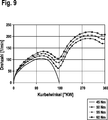
Die drei ermittelten Ansteuerdauerkennlinien
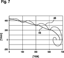
In
Auch hier liegen die drei für Injektor
Alternativ zum genannten Szenario, in welchem zwei orthogonale Injektoren
Ähnlich wie in
Weil für den Leitzylinder
Nach dem Stand der Technik ist es erforderlich, eine Nullmengenkalibrierung während einer Schubphase der Brennkraftmaschine
Wird die Drosselklappe
Bei geschlossener Drosselklappe
Die Nullmengenkalibrierung beginnt bei einer Ansteuerdauer, die sicher nicht zu einer Einspritzung von Kraftstoff führt. Bei jeder Auslaufphase wird die Ansteuerdauer inkrementell erhöht, bis es zu einer Einspritzung mit Verbrennung kommt. Eine Erkennung erfolgt durch den Vergleich des gemessenen Mengenersatzsignals S, in diesem Fall das Signal des Kurbelwellensensors
Um die Bedingungen für eine Nullmengenkalibrierung für den jeweiligen Injektor
Dreht die Brennkraftmaschine
Es ist auch möglich, die Nullmengenkalibrierung in einer Startphase oder Anlaufphase der Brennkraftmaschine
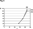
Ein zur Startphase gehörendes Referenzdrehzahlsignal zeigt
Bei einem Startdrehmoment von 45 Nm wird bei voller Ladung des ersten Zylinders
Das Referenzdrehzahlsignal wird durch Messung und Speicherung weiterer zugehöriger Daten, wie beispielsweise Reibung der Brennkraftmaschine in Abhängigkeit der Temperatur, Ansteuerdauer der Injektoren, Starterdrehzahl (für die Nullmengenkalibrierung in der Startphase), Stellung der Drosselklappe
Es versteht sich von selbst, dass an Stelle des Drehzahlsignals eines Kurbelwellensensors
ZITATE ENTHALTEN IN DER BESCHREIBUNG QUOTES INCLUDE IN THE DESCRIPTION
Diese Liste der vom Anmelder aufgeführten Dokumente wurde automatisiert erzeugt und ist ausschließlich zur besseren Information des Lesers aufgenommen. Die Liste ist nicht Bestandteil der deutschen Patent- bzw. Gebrauchsmusteranmeldung. Das DPMA übernimmt keinerlei Haftung für etwaige Fehler oder Auslassungen.This list of the documents listed by the applicant has been generated automatically and is included solely for the better information of the reader. The list is not part of the German patent or utility model application. The DPMA assumes no liability for any errors or omissions.
Zitierte PatentliteraturCited patent literature
- DE 19945618 A1 [0002] DE 19945618 A1 [0002]
- DE 102008002482 A1 [0004, 0047] DE 102008002482 A1 [0004, 0047]
- DE 102004001119 A1 [0005, 0044] DE 102004001119 A1 [0005, 0044]
- DE 102006026640 A1 [0006] DE 102006026640 A1 [0006]
Claims (11)
Priority Applications (6)
| Application Number | Priority Date | Filing Date | Title |
|---|---|---|---|
| DE102012201601A DE102012201601A1 (en) | 2012-02-03 | 2012-02-03 | Method for controlling an internal combustion engine |
| JP2014555136A JP5933760B2 (en) | 2012-02-03 | 2013-01-14 | Control method for internal combustion engine |
| US14/376,351 US20150053179A1 (en) | 2012-02-03 | 2013-01-14 | Method for controlling an internal combustion engine |
| KR1020147021624A KR20140119086A (en) | 2012-02-03 | 2013-01-14 | Method for controlling an internal combustion engine |
| PCT/EP2013/050568 WO2013113542A1 (en) | 2012-02-03 | 2013-01-14 | Method for controlling an internal combustion engine |
| EP13700554.2A EP2809928A1 (en) | 2012-02-03 | 2013-01-14 | Method for controlling an internal combustion engine |
Applications Claiming Priority (1)
| Application Number | Priority Date | Filing Date | Title |
|---|---|---|---|
| DE102012201601A DE102012201601A1 (en) | 2012-02-03 | 2012-02-03 | Method for controlling an internal combustion engine |
Publications (1)
| Publication Number | Publication Date |
|---|---|
| DE102012201601A1 true DE102012201601A1 (en) | 2013-08-08 |
Family
ID=47563497
Family Applications (1)
| Application Number | Title | Priority Date | Filing Date |
|---|---|---|---|
| DE102012201601A Withdrawn DE102012201601A1 (en) | 2012-02-03 | 2012-02-03 | Method for controlling an internal combustion engine |
Country Status (6)
| Country | Link |
|---|---|
| US (1) | US20150053179A1 (en) |
| EP (1) | EP2809928A1 (en) |
| JP (1) | JP5933760B2 (en) |
| KR (1) | KR20140119086A (en) |
| DE (1) | DE102012201601A1 (en) |
| WO (1) | WO2013113542A1 (en) |
Families Citing this family (3)
| Publication number | Priority date | Publication date | Assignee | Title |
|---|---|---|---|---|
| US9476377B2 (en) * | 2013-03-22 | 2016-10-25 | Cummins Inc. | System, method, and apparatus for fuel injection control |
| GB2533464A (en) * | 2015-10-20 | 2016-06-22 | Gm Global Tech Operations Llc | Method of operating a fuel injector of an internal combustion engine |
| KR102541073B1 (en) * | 2021-11-03 | 2023-06-08 | 주식회사 현대케피코 | Apparatus and method for detecting opening time of injection nozzle of injector |
Citations (4)
| Publication number | Priority date | Publication date | Assignee | Title |
|---|---|---|---|---|
| DE19945618A1 (en) | 1999-09-23 | 2001-03-29 | Bosch Gmbh Robert | Control method for fuel injection system in internal combustion engine by storing drive period at which change in signal occurs as minimum drive period |
| DE102004001119A1 (en) | 2004-01-07 | 2005-08-18 | Robert Bosch Gmbh | Method and device for controlling an internal combustion engine |
| DE102006026640A1 (en) | 2006-06-08 | 2007-12-13 | Robert Bosch Gmbh | Method for operating an internal combustion engine |
| DE102008002482A1 (en) | 2008-06-17 | 2009-12-24 | Robert Bosch Gmbh | Method and device for calibrating a Kraftstoffzumesssystems an internal combustion engine, in particular a motor vehicle |
Family Cites Families (4)
| Publication number | Priority date | Publication date | Assignee | Title |
|---|---|---|---|---|
| JP3812706B2 (en) * | 1999-10-18 | 2006-08-23 | 三菱電機株式会社 | Fuel injection control device for internal combustion engine |
| DE102004046083B4 (en) * | 2004-09-23 | 2016-03-17 | Robert Bosch Gmbh | Method and device for controlling an internal combustion engine |
| DE102005017130A1 (en) * | 2005-04-14 | 2006-10-19 | Robert Bosch Gmbh | Control method for an internal combustion engine uses an adjusting element to apportion an amount of fuel by relying on a triggering period |
| DE102006002738A1 (en) * | 2006-01-20 | 2007-08-02 | Robert Bosch Gmbh | Control system for fuel injectors, at a motor common rail assembly, uses signals and adapted correction values to maintain a long-term consistent performance without sensors/actuators |
-
2012
- 2012-02-03 DE DE102012201601A patent/DE102012201601A1/en not_active Withdrawn
-
2013
- 2013-01-14 JP JP2014555136A patent/JP5933760B2/en not_active Expired - Fee Related
- 2013-01-14 WO PCT/EP2013/050568 patent/WO2013113542A1/en active Application Filing
- 2013-01-14 US US14/376,351 patent/US20150053179A1/en not_active Abandoned
- 2013-01-14 KR KR1020147021624A patent/KR20140119086A/en not_active Application Discontinuation
- 2013-01-14 EP EP13700554.2A patent/EP2809928A1/en not_active Withdrawn
Patent Citations (4)
| Publication number | Priority date | Publication date | Assignee | Title |
|---|---|---|---|---|
| DE19945618A1 (en) | 1999-09-23 | 2001-03-29 | Bosch Gmbh Robert | Control method for fuel injection system in internal combustion engine by storing drive period at which change in signal occurs as minimum drive period |
| DE102004001119A1 (en) | 2004-01-07 | 2005-08-18 | Robert Bosch Gmbh | Method and device for controlling an internal combustion engine |
| DE102006026640A1 (en) | 2006-06-08 | 2007-12-13 | Robert Bosch Gmbh | Method for operating an internal combustion engine |
| DE102008002482A1 (en) | 2008-06-17 | 2009-12-24 | Robert Bosch Gmbh | Method and device for calibrating a Kraftstoffzumesssystems an internal combustion engine, in particular a motor vehicle |
Also Published As
| Publication number | Publication date |
|---|---|
| KR20140119086A (en) | 2014-10-08 |
| EP2809928A1 (en) | 2014-12-10 |
| US20150053179A1 (en) | 2015-02-26 |
| JP5933760B2 (en) | 2016-06-15 |
| WO2013113542A1 (en) | 2013-08-08 |
| JP2015505591A (en) | 2015-02-23 |
Similar Documents
| Publication | Publication Date | Title |
|---|---|---|
| DE102008002121B4 (en) | Method and control unit for calibrating an injection valve of an internal combustion engine, computer program and computer program product | |
| DE102008043165B4 (en) | Method and device for calibrating the pre-injection quantity of an internal combustion engine, in particular a motor vehicle | |
| DE10257686A1 (en) | Method for adjusting the characteristics of an injector | |
| DE102006026640A1 (en) | Method for operating an internal combustion engine | |
| DE102011086531A1 (en) | Method for diagnosing fuel injectors | |
| DE102008040227A1 (en) | Method and apparatus for pressure wave compensation in successive injections in an injection system of an internal combustion engine | |
| WO2013092190A1 (en) | Method and device for zero quantity calibration of a fuel injector valve | |
| WO2007071502A1 (en) | Method for metering fuels to combustion chambers of an internal combustion engine | |
| DE102005059909A1 (en) | Method for controlling an internal combustion engine | |
| DE102010038779A1 (en) | Method for operating an internal combustion engine having a plurality of combustion chambers and internal combustion engine having a plurality of combustion chambers | |
| DE102006048227B4 (en) | Method and device for determining an operating characteristic of an injection system and a correspondingly equipped internal combustion engine | |
| WO2012055680A1 (en) | Method for monitoring adaptation of an injection time of an injection valve of an internal combustion engine | |
| DE102012201601A1 (en) | Method for controlling an internal combustion engine | |
| WO2013083366A1 (en) | Method for learning a minimum actuation duration of injection valves of an internal combustion engine | |
| DE102008041746A1 (en) | A system for learning a deviation of an actual injection amount from a target injection amount | |
| EP2699783A1 (en) | Method and device for calibrating a fuel metering system of a motor vehicle | |
| DE102008005154A1 (en) | Method and device for monitoring a motor control unit | |
| AT517216B1 (en) | Internal combustion engine with a control device | |
| WO2017097615A1 (en) | Method for operating an internal combustion engine | |
| DE102015223862A1 (en) | Method and device for operating an internal combustion engine, in particular a motor vehicle with dual fuel injection | |
| DE102009052219A1 (en) | Method for operating an internal combustion engine with multiple combustion in a work cycle | |
| DE102008001784B4 (en) | Control device, method, computer program and computer program product for operating an internal combustion engine | |
| DE102010063380A1 (en) | Method for operating an internal combustion engine | |
| WO2017050547A1 (en) | Method and device for operating an internal combustion engine, in particular of a motor vehicle with dual fuel injection | |
| WO2017036682A1 (en) | Method for determining the evaporated portion of a fuel quantity applied by way of port fuel injection |
Legal Events
| Date | Code | Title | Description |
|---|---|---|---|
| R119 | Application deemed withdrawn, or ip right lapsed, due to non-payment of renewal fee |