DE102012201203A1 - Water-cooled dosing module - Google Patents
Water-cooled dosing module Download PDFInfo
- Publication number
- DE102012201203A1 DE102012201203A1 DE102012201203A DE102012201203A DE102012201203A1 DE 102012201203 A1 DE102012201203 A1 DE 102012201203A1 DE 102012201203 A DE102012201203 A DE 102012201203A DE 102012201203 A DE102012201203 A DE 102012201203A DE 102012201203 A1 DE102012201203 A1 DE 102012201203A1
- Authority
- DE
- Germany
- Prior art keywords
- dosing module
- heat sink
- cooling fluid
- dosing
- reducing agent
- Prior art date
- Legal status (The legal status is an assumption and is not a legal conclusion. Google has not performed a legal analysis and makes no representation as to the accuracy of the status listed.)
- Withdrawn
Links
Images


Classifications
-
- F—MECHANICAL ENGINEERING; LIGHTING; HEATING; WEAPONS; BLASTING
- F01—MACHINES OR ENGINES IN GENERAL; ENGINE PLANTS IN GENERAL; STEAM ENGINES
- F01N—GAS-FLOW SILENCERS OR EXHAUST APPARATUS FOR MACHINES OR ENGINES IN GENERAL; GAS-FLOW SILENCERS OR EXHAUST APPARATUS FOR INTERNAL COMBUSTION ENGINES
- F01N3/00—Exhaust or silencing apparatus having means for purifying, rendering innocuous, or otherwise treating exhaust
- F01N3/08—Exhaust or silencing apparatus having means for purifying, rendering innocuous, or otherwise treating exhaust for rendering innocuous
- F01N3/10—Exhaust or silencing apparatus having means for purifying, rendering innocuous, or otherwise treating exhaust for rendering innocuous by thermal or catalytic conversion of noxious components of exhaust
- F01N3/18—Exhaust or silencing apparatus having means for purifying, rendering innocuous, or otherwise treating exhaust for rendering innocuous by thermal or catalytic conversion of noxious components of exhaust characterised by methods of operation; Control
- F01N3/20—Exhaust or silencing apparatus having means for purifying, rendering innocuous, or otherwise treating exhaust for rendering innocuous by thermal or catalytic conversion of noxious components of exhaust characterised by methods of operation; Control specially adapted for catalytic conversion ; Methods of operation or control of catalytic converters
- F01N3/2066—Selective catalytic reduction [SCR]
-
- F—MECHANICAL ENGINEERING; LIGHTING; HEATING; WEAPONS; BLASTING
- F01—MACHINES OR ENGINES IN GENERAL; ENGINE PLANTS IN GENERAL; STEAM ENGINES
- F01N—GAS-FLOW SILENCERS OR EXHAUST APPARATUS FOR MACHINES OR ENGINES IN GENERAL; GAS-FLOW SILENCERS OR EXHAUST APPARATUS FOR INTERNAL COMBUSTION ENGINES
- F01N2260/00—Exhaust treating devices having provisions not otherwise provided for
- F01N2260/02—Exhaust treating devices having provisions not otherwise provided for for cooling the device
- F01N2260/024—Exhaust treating devices having provisions not otherwise provided for for cooling the device using a liquid
-
- F—MECHANICAL ENGINEERING; LIGHTING; HEATING; WEAPONS; BLASTING
- F01—MACHINES OR ENGINES IN GENERAL; ENGINE PLANTS IN GENERAL; STEAM ENGINES
- F01N—GAS-FLOW SILENCERS OR EXHAUST APPARATUS FOR MACHINES OR ENGINES IN GENERAL; GAS-FLOW SILENCERS OR EXHAUST APPARATUS FOR INTERNAL COMBUSTION ENGINES
- F01N2610/00—Adding substances to exhaust gases
- F01N2610/02—Adding substances to exhaust gases the substance being ammonia or urea
-
- F—MECHANICAL ENGINEERING; LIGHTING; HEATING; WEAPONS; BLASTING
- F01—MACHINES OR ENGINES IN GENERAL; ENGINE PLANTS IN GENERAL; STEAM ENGINES
- F01N—GAS-FLOW SILENCERS OR EXHAUST APPARATUS FOR MACHINES OR ENGINES IN GENERAL; GAS-FLOW SILENCERS OR EXHAUST APPARATUS FOR INTERNAL COMBUSTION ENGINES
- F01N2610/00—Adding substances to exhaust gases
- F01N2610/11—Adding substances to exhaust gases the substance or part of the dosing system being cooled
-
- F—MECHANICAL ENGINEERING; LIGHTING; HEATING; WEAPONS; BLASTING
- F01—MACHINES OR ENGINES IN GENERAL; ENGINE PLANTS IN GENERAL; STEAM ENGINES
- F01N—GAS-FLOW SILENCERS OR EXHAUST APPARATUS FOR MACHINES OR ENGINES IN GENERAL; GAS-FLOW SILENCERS OR EXHAUST APPARATUS FOR INTERNAL COMBUSTION ENGINES
- F01N2610/00—Adding substances to exhaust gases
- F01N2610/14—Arrangements for the supply of substances, e.g. conduits
- F01N2610/1453—Sprayers or atomisers; Arrangement thereof in the exhaust apparatus
-
- F—MECHANICAL ENGINEERING; LIGHTING; HEATING; WEAPONS; BLASTING
- F01—MACHINES OR ENGINES IN GENERAL; ENGINE PLANTS IN GENERAL; STEAM ENGINES
- F01N—GAS-FLOW SILENCERS OR EXHAUST APPARATUS FOR MACHINES OR ENGINES IN GENERAL; GAS-FLOW SILENCERS OR EXHAUST APPARATUS FOR INTERNAL COMBUSTION ENGINES
- F01N3/00—Exhaust or silencing apparatus having means for purifying, rendering innocuous, or otherwise treating exhaust
- F01N3/08—Exhaust or silencing apparatus having means for purifying, rendering innocuous, or otherwise treating exhaust for rendering innocuous
- F01N3/10—Exhaust or silencing apparatus having means for purifying, rendering innocuous, or otherwise treating exhaust for rendering innocuous by thermal or catalytic conversion of noxious components of exhaust
- F01N3/18—Exhaust or silencing apparatus having means for purifying, rendering innocuous, or otherwise treating exhaust for rendering innocuous by thermal or catalytic conversion of noxious components of exhaust characterised by methods of operation; Control
- F01N3/20—Exhaust or silencing apparatus having means for purifying, rendering innocuous, or otherwise treating exhaust for rendering innocuous by thermal or catalytic conversion of noxious components of exhaust characterised by methods of operation; Control specially adapted for catalytic conversion ; Methods of operation or control of catalytic converters
- F01N3/2066—Selective catalytic reduction [SCR]
- F01N3/208—Control of selective catalytic reduction [SCR], e.g. dosing of reducing agent
-
- Y—GENERAL TAGGING OF NEW TECHNOLOGICAL DEVELOPMENTS; GENERAL TAGGING OF CROSS-SECTIONAL TECHNOLOGIES SPANNING OVER SEVERAL SECTIONS OF THE IPC; TECHNICAL SUBJECTS COVERED BY FORMER USPC CROSS-REFERENCE ART COLLECTIONS [XRACs] AND DIGESTS
- Y02—TECHNOLOGIES OR APPLICATIONS FOR MITIGATION OR ADAPTATION AGAINST CLIMATE CHANGE
- Y02T—CLIMATE CHANGE MITIGATION TECHNOLOGIES RELATED TO TRANSPORTATION
- Y02T10/00—Road transport of goods or passengers
- Y02T10/10—Internal combustion engine [ICE] based vehicles
- Y02T10/12—Improving ICE efficiencies
Abstract
Die Erfindung bezieht sich auf ein Dosiermodul (10) zum Eindosieren eines Reduktionsmittels in einen Abgastrakt einer Verbrennungskraftmaschine. Das Dosiermodul (10) umfasst mindestens einen Kühlkörper (22, 24), der von einem Kühlfluid, das der Kühlung der Verbrennungskraftmaschine dient, durchströmt ist. Im oberen Bereich des Dosiermodules (10) befindet sich eine elektrische Kontaktierung (20). Das Dosiermodul (10) ist von einer Volleinhausung (38) umschlossen. Diese umfasst einen oberen und einen unteren Kühlkörper (22, 24, 24). Diese werden von einer gerichteten Kühlfluidströmung (34), ausgehend von Ventilspitzenbereich (18) in Richtung der elektrischen Kontaktierung (20) durchströmt.The invention relates to a dosing module (10) for dosing a reducing agent in an exhaust gas tract of an internal combustion engine. The metering module (10) comprises at least one heat sink (22, 24) which is flowed through by a cooling fluid which serves to cool the internal combustion engine. In the upper part of the metering module (10) there is an electrical contact (20). The metering module (10) is enclosed by a full housing (38). This comprises an upper and a lower heat sink (22, 24, 24). These are flowed through by a directed cooling fluid flow (34), starting from the valve tip region (18) in the direction of the electrical contact (20).
Description
Stand der TechnikState of the art
Der Ventilaufnahmekörper weist an seiner der Abgasleitung abgewandten Seite eine dem Durchmesser des Einspritzventiles angepasste Ausnehmung auf. Diese wird von der Innenwandung begrenzt, so dass im eingebauten Zustand des Einspritzventiles die Austrittsöffnung des Einspritzventiles kurz vor oder in Höhe der mit einer Durchtrittsöffnung für das einzubringende Reduktionsmittel versehenen Wandung der Abgasleitung liegt. The valve receiving body has on its side facing away from the exhaust pipe on a diameter of the injection valve adapted to recess. This is limited by the inner wall, so that in the installed state of the injection valve, the outlet opening of the injection valve is located shortly before or in the amount of provided with a passage opening for the reducing agent to be introduced wall of the exhaust pipe.
Bei der Entwicklung von Dosiermodulen (Advanced Dosing Modul = aDm) wird ein Einspritzventil zum Zwecke der Harnstoffdosierung aufgenommen. Um mit der Ventilspitze bei diesem Dosierventil so nah wie möglich an den Abgasstrom zu kommen, wird in diesem Dosiermodul die Ventilaufnahme aktiv gekühlt. Dies geschieht über einen Anschluss des Kühlkörpers an den Kühlmittelkreislauf des Fahrzeugs. Dadurch wird sichergestellt, dass auch bei abgasnaher Positionierung des Dosierventiles die Ventilspitzentemperatur nicht über 120°C ansteigt. In the development of dosing modules (Advanced Dosing Module = aDm), an injection valve is added for the purpose of urea dosing. In order to get as close as possible to the exhaust gas flow with the valve tip in this metering valve, the valve seat is actively cooled in this metering module. This is done via a connection of the heat sink to the coolant circuit of the vehicle. This ensures that the valve tip temperature does not rise above 120 ° C even when the metering valve is positioned close to the exhaust gas.
Ein Nachteil dieser Ausführung liegt in einer fehlenden Kühlwirkung im oberen Bereich, d.h. im Bereich der elektrischen Kontaktierung des Dosierventiles. Dadurch ist es nicht möglich, dieses Dosiermodul in Umgebungstemperaturen einzusetzen, die größer als 160°C sind. Die elektrische Steckerverbindung und die Spule des Dosierventiles nehmen bei Temperaturen oberhalb von 160°C Schaden, so dass mit einem Ausfall des Ventiles bzw. der elektrischen Kontaktierung des Dosierventiles zu rechnen ist. A disadvantage of this embodiment is a lack of cooling effect in the upper area, i. in the field of electrical contacting of the metering valve. This means that it is not possible to use this dosing module in ambient temperatures greater than 160 ° C. The electrical plug connection and the coil of the metering valve take damage at temperatures above 160 ° C, so that is to be expected with a failure of the valve or the electrical contacting of the metering valve.
Darstellung der ErfindungPresentation of the invention
Erfindungsgemäß wird ein Dosiermodul vorgeschlagen, welches dem Einbringen eines Reduktionsmittels in den Abgasstrom einer Verbrennungskraftmaschine dient, welches eine vollständige Einhausung umfasst und mit seitlichen hydraulischen Anschlüssen versehen ist, die eine mögliche Kontaktierung nahezu entlang seines gesamten Umfanges, d.h. 360° ermöglicht. Damit besteht die Möglichkeit, das erfindungsgemäß vorgeschlagene Dosiermodul in den Motorraum eines Fahrzeugs zu verlegen, in dem Temperaturen über 200°C auftreten können, wobei den dort herrschenden beengten Bauraumvorgaben in vollem Umfang Rechnung getragen werden kann. Im Allgemeinen werden Dosierventile im Unterbodenbereich eines Fahrzeugs eingebaut, wo wesentlich mehr Bauraum zur Verfügung steht. According to the invention, a metering module is proposed, which serves to introduce a reducing agent into the exhaust gas stream of an internal combustion engine, which comprises a complete housing and is provided with lateral hydraulic connections which allow a possible contacting almost along its entire circumference, i. 360 ° possible. This makes it possible to move the metering module proposed in the invention in the engine compartment of a vehicle, can occur in the temperatures above 200 ° C, where the prevailing cramped space requirements can be fully taken into account. In general, metering valves are installed in the underfloor area of a vehicle, where much more space is available.
Durch die erfindungsgemäß vorgeschlagene Lösung kann einerseits den beengten Einbauverhältnissen im Motorraum eines Fahrzeugs Rechnung getragen werden und andererseits ist sichergestellt, dass durch die erfindungsgemäß vorgeschlagene Kompletteinhausung des Dosierventiles dieses Temperaturen von 200°C und mehr standhalten kann. By inventively proposed solution, on the one hand the tight installation conditions in the engine compartment of a vehicle can be taken into account and on the other hand it is ensured that can withstand the invention proposed by the complete dosing of the metering this temperature of 200 ° C and more.
Durch die erfindungsgemäß vorgeschlagene Lösung wird insbesondere durch die komplette Einhausung des Dosiermodules die Kühlung des kompletten Dosiermoduls gewährleistet. In vorteilhafter Weise kann die Kompletteinhausung (Volleinhausung) durch zwei zusätzliche Teile realisiert werden, die insbesondere als Blechteile ausgebildet sind und auf den unteren Kühlkörperabschnitt aufgesetzt werden. Durch diesen zusätzlichen Kühlkörper ist es möglich, auch den oberen Bereich des Ventiles zu kühlen, in dem die elektrische Kontaktierung, beispielsweise dargestellt durch einen seitlichen Steckerabgang, liegt. Beispielsweise kann der obere zusätzliche, auf den unteren Kühlkörper aufgesetzte Kühlkörper durch eine stoffschlüssige Verbindung, so zum Beispiel über eine Laserverschweißung mit dem unteren Kühlkörper verbunden sein. By inventively proposed solution, the cooling of the entire metering module is ensured in particular by the complete enclosure of the dosing. Advantageously, the Gesamtinhausung (full enclosure) can be realized by two additional parts, which are designed in particular as sheet metal parts and are placed on the lower heat sink section. By this additional heat sink, it is possible to cool the upper portion of the valve, in which the electrical contact, for example, represented by a lateral connector outlet, is located. For example, the upper additional, patch on the lower heat sink Heatsink by a cohesive connection, so for example be connected via a laser welding to the lower heat sink.
Bei der erfindungsgemäß vorgeschlagenen Lösung der Ummantelung des Ventiles mit einer Volleinhausung, wird vom Fahrzeug kommendes Kühlmittel zuerst in den unteren Kühlkörper eingeleitet, so dass dort die größte Kühlleistung an der heißesten Stelle, d.h. an der Ventilspitze des Ventiles vorliegt. Dadurch wird eine optimale Kühlung des Ventilspitzenbereiches des erfindungsgemäß vorgeschlagenen Dosiermoduls erreicht. Vom unteren Kühlkörper aus tritt das nunmehr aufgrund der Abkühlung der Ventilspitze durch Wärmeaufnahme erwärmte Kühlfluid im Bereich der Laserverschweißung an der Innenseite in den oberen zusätzlichen Kühlkörper über. Somit kann auch der obere Bereich des Dosiermodules, in dem die elektrische Verbindung sowie die Magnetspule liegt, gekühlt werden. In fertigungstechnisch günstiger Weise ist die Volleinhausung gemäß der erfindungsgemäß vorgeschlagenen Lösung vollständig durch Tiefzieh- und Biegeteile darstellbar, was eine kostengünstige Herstellung der erfindungsgemäß vorgeschlagenen, das Dosiermodul umgebenden Volleinhausung ermöglicht. In the present invention proposed solution of the jacket of the valve with a full enclosure, coming from the vehicle coolant is first introduced into the lower heat sink, so that there the greatest cooling capacity at the hottest point, i. is present at the valve tip of the valve. As a result, optimum cooling of the valve tip region of the dosing module proposed according to the invention is achieved. From the lower heat sink, the cooling fluid, which has now been heated due to the cooling of the valve tip due to the absorption of heat, passes in the area of the laser welding on the inside into the upper additional heat sink. Thus, the upper portion of the Dosiermodules in which the electrical connection and the solenoid is located, to be cooled. In manufacturing technology favorable way, the full enclosure according to the invention proposed solution is completely represented by thermoforming and bending parts, which allows a cost-effective production of the inventively proposed, the dosing module surrounding full enclosure.
Die erfindungsgemäß vorgeschlagene Lösung zeichnet sich zudem dadurch aus, dass die hydraulische Anschlüsse in hoher Variabilität ausgebildet werden können. So kann beispielsweise der hydraulische Anschluss für die Zuleitung des Reduktionsmittels, bei dem es sich beispielsweise um eine Harnstoff-Wasser-Lösung (HWL) oder um Harnstoff (AdBlue) handeln kann, theoretisch entlang des vollen Umfanges, d.h. in 360°, so zum Beispiel in Rasterungen von 45° oder 30° oder weniger positioniert werden.The proposed solution according to the invention is also characterized by the fact that the hydraulic connections can be formed in high variability. Thus, for example, the hydraulic port for the supply of the reducing agent, which may be, for example, a urea-water solution (HWL) or urea (AdBlue), theoretically along the full extent, i. in 360 °, so for example in rasters of 45 ° or 30 ° or less are positioned.
Der hydraulische Anschluss für den Kühlwasserzulauf im unteren Bereich des Ventilkörpers kann um 180° verdrehbar ausgebildet werden, so zum Beispiel in Abstufungen von 15° oder 20° oder weniger mit Hilfe von gewinkelten Anschlüssen ausgeführt werden.The hydraulic connection for the cooling water inlet in the lower region of the valve body can be made rotatable by 180 °, for example in increments of 15 ° or 20 ° or less by means of angled connections.
Aufgrund dieser Variabilität der Lage des Kühlwassereintritts, des Kühlwasseraustritts sowie des Reduktionsmittelzulaufes, kann den beengten Bauraumverhältnissen, die im Motorraum von Fahrzeugen vorliegen, Rechnung getragen werden. Durch die hohe Variabilität der Kühlwasserzu- bzw. Kühlwasserabläufe kann des Weiteren eine hohe Varianz, d.h. eine hohe Variabilität im Hinblick auf unterschiedliche Kundenanforderungen, abhängig vom zum Verfügung stehenden Bauraum sichergestellt werden. Des Weiteren lässt sich durch die erfindungsgemäß vorgeschlagene Lösung in vorteilhafter Weise erreichen, dass nunmehr aufgrund der Volleinhausung eine Kühlung des Dosiermodules auch im Bereich von dessen elektrischer Kontaktierung gewährleistet ist.Due to this variability of the position of the cooling water inlet, the cooling water outlet and the reducing agent inlet, the tight space conditions that exist in the engine compartment of vehicles, can be taken into account. Furthermore, due to the high variability of the cooling water supply and / or cooling water flows, a high variance, i. a high variability with regard to different customer requirements, depending on the available space can be ensured. Furthermore, can be achieved by the proposed solution according to the invention in an advantageous manner that now due to the full enclosure cooling of the dosing is guaranteed even in the range of its electrical contact.
Vorteile der ErfindungAdvantages of the invention
Die Vorteile der erfindungsgemäß vorgeschlagenen Lösung liegen – wie oben stehend bereits ausgeführt – in einer erhöhten Temperaturbeständigkeit des erfindungsgemäß vorgeschlagenen Dosiermodules, was dessen Einbau auch im Motorraum eines Fahrzeugs ermöglicht. Des Weiteren kann durch die hohe Varianz der Positionierung der Kühlwasserzuläufe bzw. des Reduktionsmittelzulaufes unterschiedlichen Einbauverhältnissen im Motorraum von Fahrzeugen Rechnung getragen werden. The advantages of the proposed solution according to the invention are - as already stated above - in an increased temperature resistance of the invention proposed dosing, which allows its installation in the engine compartment of a vehicle. Furthermore, due to the high variance of the positioning of the cooling water inlets or of the reducing agent feed, different installation conditions in the engine compartment of vehicles can be taken into account.
Als weiterer Vorteil der erfindungsgemäß vorgeschlagenen Lösung ist zu nennen, dass durch ein radiales Anbringen der Kühlwasseranschlüsse ein kleinerer Querschnitt des Kühlkörpers erreicht werden kann. Dies wiederum führt zu einer verkleinerten Auslegung des Dicht- bzw. Befestigungsbereiches. Dadurch wiederum können eine kleinere Dichtung sowie eine kleinere Schelle verwendet werden, was den Bauraum günstig beeinflusst, so dass Kundenbauraumforderungen besser Rechnung getragen werden kann.A further advantage of the proposed solution according to the invention is that a smaller cross section of the heat sink can be achieved by a radial attachment of the cooling water connections. This in turn leads to a smaller design of the sealing or fastening area. In turn, a smaller seal and a smaller clamp can be used, which favorably affects the space, so that customer space requirements can be better taken into account.
Kurze Beschreibung der ZeichnungenBrief description of the drawings
Anhand der Zeichnung wird die Erfindung nachstehend eingehender beschrieben.With reference to the drawing, the invention will be described below in more detail.
Es zeigt:It shows:
Ausführungsvariantenvariants
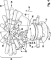
Ein erfindungsgemäß vorgeschlagenes Dosiermodul
Die Schnittdarstellung gemäß
Wie der Darstellung gemäß
In der Schnittdarstellung gemäß
Aus der Darstellung gemäß
Die Darstellung gemäß
Da nunmehr durch die erfindungsgemäß vorgeschlagene Kühlung mittels einer Volleinhausung
Wie aus der Darstellung gemäß
Aus der Darstellung gemäß
Die perspektivische Darstellung gemäß
Darüber hinaus ist in
Aus
Normalerweise wird nur ein Kühlfluidzulauf
Aus der Darstellung gemäß
Der Darstellung gemäß
Aus der perspektivischen Darstellung gemäß
Aus der Darstellung gemäß
Unterhalb des verdrehbaren Flansches
Das vorstehend in Zusammenhang mit den
Aus der Darstellung gemäß
Aus
Unterhalb der durch die verschiedenen Positionen
ZITATE ENTHALTEN IN DER BESCHREIBUNG QUOTES INCLUDE IN THE DESCRIPTION
Diese Liste der vom Anmelder aufgeführten Dokumente wurde automatisiert erzeugt und ist ausschließlich zur besseren Information des Lesers aufgenommen. Die Liste ist nicht Bestandteil der deutschen Patent- bzw. Gebrauchsmusteranmeldung. Das DPMA übernimmt keinerlei Haftung für etwaige Fehler oder Auslassungen.This list of the documents listed by the applicant has been generated automatically and is included solely for the better information of the reader. The list is not part of the German patent or utility model application. The DPMA assumes no liability for any errors or omissions.
Zitierte PatentliteraturCited patent literature
- DE 4436397 A1 [0001] DE 4436397 A1 [0001]
- DE 19856366 C1 [0002] DE 19856366 C1 [0002]
Claims (14)
Priority Applications (7)
| Application Number | Priority Date | Filing Date | Title |
|---|---|---|---|
| DE102012201203A DE102012201203A1 (en) | 2012-01-27 | 2012-01-27 | Water-cooled dosing module |
| CN201380006488.2A CN104066946B (en) | 2012-01-27 | 2013-01-04 | The metering module of water cooling |
| PCT/EP2013/050076 WO2013110484A1 (en) | 2012-01-27 | 2013-01-04 | Water-cooled dosing module |
| EP13700067.5A EP2807351B1 (en) | 2012-01-27 | 2013-01-04 | Water-cooled dosing module |
| RU2014134738A RU2618750C2 (en) | 2012-01-27 | 2013-01-04 | Metering unit with liquid cooling |
| JP2014552578A JP5961706B2 (en) | 2012-01-27 | 2013-01-04 | Water-cooled metering module |
| US14/373,676 US9194270B2 (en) | 2012-01-27 | 2013-01-04 | Water-cooled dosing module |
Applications Claiming Priority (1)
| Application Number | Priority Date | Filing Date | Title |
|---|---|---|---|
| DE102012201203A DE102012201203A1 (en) | 2012-01-27 | 2012-01-27 | Water-cooled dosing module |
Publications (1)
| Publication Number | Publication Date |
|---|---|
| DE102012201203A1 true DE102012201203A1 (en) | 2013-08-01 |
Family
ID=47522658
Family Applications (1)
| Application Number | Title | Priority Date | Filing Date |
|---|---|---|---|
| DE102012201203A Withdrawn DE102012201203A1 (en) | 2012-01-27 | 2012-01-27 | Water-cooled dosing module |
Country Status (7)
| Country | Link |
|---|---|
| US (1) | US9194270B2 (en) |
| EP (1) | EP2807351B1 (en) |
| JP (1) | JP5961706B2 (en) |
| CN (1) | CN104066946B (en) |
| DE (1) | DE102012201203A1 (en) |
| RU (1) | RU2618750C2 (en) |
| WO (1) | WO2013110484A1 (en) |
Cited By (3)
| Publication number | Priority date | Publication date | Assignee | Title |
|---|---|---|---|---|
| DE102012205389A1 (en) | 2012-04-03 | 2013-10-10 | Robert Bosch Gmbh | Cooling device for connection piece |
| WO2014035956A1 (en) * | 2012-08-27 | 2014-03-06 | Continental Automotive Systems, Inc. | Reductant delivery unit for automotive selective catalytic reduction systems- active cooling |
| DE102020101964B4 (en) | 2019-02-18 | 2023-11-02 | Denso Corporation | Cooling device |
Families Citing this family (11)
| Publication number | Priority date | Publication date | Assignee | Title |
|---|---|---|---|---|
| US10440626B2 (en) * | 2015-03-20 | 2019-10-08 | Parallel Wireless, Inc. | Content-aware inter-RAT RAB steering |
| GB2539888A (en) * | 2015-06-29 | 2017-01-04 | Delphi Int Operations Luxembourg Sarl | Reductant injector cooling system |
| JP6587215B2 (en) * | 2016-06-15 | 2019-10-09 | 株式会社デンソー | Injection valve cooling system |
| US9890680B1 (en) * | 2016-11-09 | 2018-02-13 | Continental Automotive Systems, Inc. | Low-cost, thermally controlled inlet reductant dosing unit |
| JP6954103B2 (en) | 2017-12-25 | 2021-10-27 | 株式会社デンソー | Cooling device for additive injection valve |
| JP6954101B2 (en) | 2017-12-25 | 2021-10-27 | 株式会社デンソー | Cooling device for additive injection valve |
| JP6954102B2 (en) * | 2017-12-25 | 2021-10-27 | 株式会社デンソー | Additive injection valve cooling device and cooling system |
| GB2571756B (en) | 2018-03-08 | 2020-06-24 | Delphi Tech Ip Ltd | Electrical connector for a SCR doser |
| DE102018209398A1 (en) * | 2018-06-13 | 2019-12-19 | Robert Bosch Gmbh | dosing |
| US10683786B2 (en) * | 2018-07-25 | 2020-06-16 | Tenneco Automotive Operating Company Inc. | Reagent injector |
| US10767533B1 (en) | 2019-02-28 | 2020-09-08 | Tenneco Automotive Operating Company Inc. | Reagent injector |
Citations (2)
| Publication number | Priority date | Publication date | Assignee | Title |
|---|---|---|---|---|
| DE4436397A1 (en) | 1994-10-12 | 1996-04-18 | Bosch Gmbh Robert | Exhaust gas aftertreatment device |
| DE19856366C1 (en) | 1998-12-07 | 2000-04-20 | Siemens Ag | Urea injection system treating exhaust gases from lean burn engine, comprises air-cooling jacket surrounding injector valve to keep it cool, so that a petrol injection valve may be used |
Family Cites Families (13)
| Publication number | Priority date | Publication date | Assignee | Title |
|---|---|---|---|---|
| DE19817994A1 (en) * | 1998-04-22 | 1999-11-04 | Emitec Emissionstechnologie | Method and device for purifying exhaust gas from an internal combustion engine containing nitrogen oxide (NO¶x¶) |
| US7066401B2 (en) * | 2002-10-02 | 2006-06-27 | Spraying Systems Co. | Lance-type liquid reducing agent spray device |
| DE102009047375B4 (en) * | 2009-12-02 | 2023-12-28 | Robert Bosch Gmbh | Dosing module with liquid cooling |
| KR101767284B1 (en) * | 2010-02-10 | 2017-08-23 | 테네코 오토모티브 오퍼레이팅 컴파니 인코포레이티드 | Pressure swirl flow injector with reduced flow variability and return flow |
| SE537642C2 (en) * | 2010-06-21 | 2015-09-08 | Scania Cv Ab | Method and apparatus for cooling a reducing agent dosing unit |
| RU2565476C2 (en) * | 2010-10-14 | 2015-10-20 | Эмитек Гезельшафт Фюр Эмиссионстехнологи Мбх | Fastener for injector |
| EP2503122B1 (en) * | 2011-03-22 | 2014-10-08 | Delphi International Operations Luxembourg S.à r.l. | Reagent dosing pump assembly |
| GB201105884D0 (en) * | 2011-04-07 | 2011-05-18 | Delphi Tech Holding Sarl | Reagent dosing connector arrangement |
| DE102011086017A1 (en) * | 2011-11-09 | 2013-05-16 | Robert Bosch Gmbh | dosing |
| DE102011086795A1 (en) * | 2011-11-22 | 2013-05-23 | Robert Bosch Gmbh | Device for cooling a metering valve |
| DE102011087085A1 (en) * | 2011-11-25 | 2013-05-29 | Robert Bosch Gmbh | Cooling device with drainage holes |
| DE102012205389A1 (en) * | 2012-04-03 | 2013-10-10 | Robert Bosch Gmbh | Cooling device for connection piece |
| US20140054394A1 (en) * | 2012-08-27 | 2014-02-27 | Continental Automotive Systems Us, Inc. | Reductant delivery unit for automotive selective catalytic reduction systems - active cooling |
-
2012
- 2012-01-27 DE DE102012201203A patent/DE102012201203A1/en not_active Withdrawn
-
2013
- 2013-01-04 RU RU2014134738A patent/RU2618750C2/en active
- 2013-01-04 WO PCT/EP2013/050076 patent/WO2013110484A1/en active Application Filing
- 2013-01-04 EP EP13700067.5A patent/EP2807351B1/en active Active
- 2013-01-04 JP JP2014552578A patent/JP5961706B2/en not_active Expired - Fee Related
- 2013-01-04 US US14/373,676 patent/US9194270B2/en not_active Expired - Fee Related
- 2013-01-04 CN CN201380006488.2A patent/CN104066946B/en active Active
Patent Citations (2)
| Publication number | Priority date | Publication date | Assignee | Title |
|---|---|---|---|---|
| DE4436397A1 (en) | 1994-10-12 | 1996-04-18 | Bosch Gmbh Robert | Exhaust gas aftertreatment device |
| DE19856366C1 (en) | 1998-12-07 | 2000-04-20 | Siemens Ag | Urea injection system treating exhaust gases from lean burn engine, comprises air-cooling jacket surrounding injector valve to keep it cool, so that a petrol injection valve may be used |
Cited By (4)
| Publication number | Priority date | Publication date | Assignee | Title |
|---|---|---|---|---|
| DE102012205389A1 (en) | 2012-04-03 | 2013-10-10 | Robert Bosch Gmbh | Cooling device for connection piece |
| US9598994B2 (en) | 2012-04-03 | 2017-03-21 | Robert Bosch Gmbh | Cooling device for connection piece |
| WO2014035956A1 (en) * | 2012-08-27 | 2014-03-06 | Continental Automotive Systems, Inc. | Reductant delivery unit for automotive selective catalytic reduction systems- active cooling |
| DE102020101964B4 (en) | 2019-02-18 | 2023-11-02 | Denso Corporation | Cooling device |
Also Published As
| Publication number | Publication date |
|---|---|
| US9194270B2 (en) | 2015-11-24 |
| CN104066946A (en) | 2014-09-24 |
| EP2807351A1 (en) | 2014-12-03 |
| RU2618750C2 (en) | 2017-05-11 |
| JP2015505350A (en) | 2015-02-19 |
| CN104066946B (en) | 2017-09-08 |
| RU2014134738A (en) | 2016-03-27 |
| JP5961706B2 (en) | 2016-08-02 |
| WO2013110484A1 (en) | 2013-08-01 |
| US20150027108A1 (en) | 2015-01-29 |
| EP2807351B1 (en) | 2017-05-17 |
Similar Documents
| Publication | Publication Date | Title |
|---|---|---|
| EP2807351B1 (en) | Water-cooled dosing module | |
| EP2776687B1 (en) | Metering module | |
| EP2834486B1 (en) | Cooling device for a fluid coupling | |
| EP2252779B1 (en) | Metering device for pollution reduction in exhaust gases | |
| DE112011103529B4 (en) | Nozzle for introducing reducing agent | |
| DE102014215084C5 (en) | Injection device and associated manufacturing process | |
| EP2783083B1 (en) | Device for cooling a dosing valve | |
| EP2627880A1 (en) | Mounting for an injector | |
| EP1192337A1 (en) | Valve seat device for a metering valve of an exhaust treatment station | |
| DE112013004205T5 (en) | Active Coolant Reducer Supply Unit for Selective Catalytic Reductant Systems for Vehicles | |
| EP2783084B1 (en) | Cooling device with drain openings for a dosing valve | |
| EP2724000B1 (en) | Cooled metering unit | |
| EP2705229B1 (en) | Injector for metering reducing agent to the exhaust gas of an internal combustion engine | |
| DE102011120457A1 (en) | Injection device for adding a liquid additive | |
| DE102010035311A1 (en) | Decoupling element, in particular for exhaust systems | |
| DE102012004595A1 (en) | Distribution module for an additive to be injected into an exhaust line | |
| DE102011088569A1 (en) | Apparatus and method for vaporizing a fluid in an exhaust line | |
| DE102007034314A1 (en) | Assembly for inserting reducing agent into exhaust pipe, particularly exhaust system of internal combustion engine, has pressure chamber, in which reducing agent is inserted on pressure lying above atmospheric pressure | |
| WO2013120651A1 (en) | Metering module for introducing a fluid substance into the exhaust gas of an internal combustion engine | |
| DE102011077972A1 (en) | Valve assembly for internal combustion engine, has valve seat arranged in region of connection piece of exhaust gas duct, and cooling device engaged with exhaust gas duct facing end of metering valve in circumferential direction | |
| DE102012217696A1 (en) | dosing | |
| DE102012202139A1 (en) | Metering module for introducing reducing agent for nitrogen oxides-constituents in exhaust gas of internal combustion engine, has adapter, on which interfaces for cooling fluid connections representing exhaust gas system are arranged | |
| DE102011077791A1 (en) | Device for introducing a reducing agent into the exhaust gas of an internal combustion engine | |
| DE102014211843A1 (en) | Device for conveying and metering a fuel | |
| DE102020131428A1 (en) | Evaporator module and exhaust aftertreatment system with such a module |
Legal Events
| Date | Code | Title | Description |
|---|---|---|---|
| R119 | Application deemed withdrawn, or ip right lapsed, due to non-payment of renewal fee |