DE102012103292A1 - Method for operating electrical powertrain of e.g. all-wheel drive motor car, involves determining powers of individual electromotors, such that resultant power dissipations of electromotors is minimized based on power dissipation map - Google Patents
Method for operating electrical powertrain of e.g. all-wheel drive motor car, involves determining powers of individual electromotors, such that resultant power dissipations of electromotors is minimized based on power dissipation map Download PDFInfo
- Publication number
- DE102012103292A1 DE102012103292A1 DE201210103292 DE102012103292A DE102012103292A1 DE 102012103292 A1 DE102012103292 A1 DE 102012103292A1 DE 201210103292 DE201210103292 DE 201210103292 DE 102012103292 A DE102012103292 A DE 102012103292A DE 102012103292 A1 DE102012103292 A1 DE 102012103292A1
- Authority
- DE
- Germany
- Prior art keywords
- electric
- drive train
- individual
- electromotors
- electric drive
- Prior art date
- Legal status (The legal status is an assumption and is not a legal conclusion. Google has not performed a legal analysis and makes no representation as to the accuracy of the status listed.)
- Pending
Links
Images
Classifications
-
- B—PERFORMING OPERATIONS; TRANSPORTING
- B60—VEHICLES IN GENERAL
- B60L—PROPULSION OF ELECTRICALLY-PROPELLED VEHICLES; SUPPLYING ELECTRIC POWER FOR AUXILIARY EQUIPMENT OF ELECTRICALLY-PROPELLED VEHICLES; ELECTRODYNAMIC BRAKE SYSTEMS FOR VEHICLES IN GENERAL; MAGNETIC SUSPENSION OR LEVITATION FOR VEHICLES; MONITORING OPERATING VARIABLES OF ELECTRICALLY-PROPELLED VEHICLES; ELECTRIC SAFETY DEVICES FOR ELECTRICALLY-PROPELLED VEHICLES
- B60L15/00—Methods, circuits, or devices for controlling the traction-motor speed of electrically-propelled vehicles
- B60L15/20—Methods, circuits, or devices for controlling the traction-motor speed of electrically-propelled vehicles for control of the vehicle or its driving motor to achieve a desired performance, e.g. speed, torque, programmed variation of speed
-
- B—PERFORMING OPERATIONS; TRANSPORTING
- B60—VEHICLES IN GENERAL
- B60L—PROPULSION OF ELECTRICALLY-PROPELLED VEHICLES; SUPPLYING ELECTRIC POWER FOR AUXILIARY EQUIPMENT OF ELECTRICALLY-PROPELLED VEHICLES; ELECTRODYNAMIC BRAKE SYSTEMS FOR VEHICLES IN GENERAL; MAGNETIC SUSPENSION OR LEVITATION FOR VEHICLES; MONITORING OPERATING VARIABLES OF ELECTRICALLY-PROPELLED VEHICLES; ELECTRIC SAFETY DEVICES FOR ELECTRICALLY-PROPELLED VEHICLES
- B60L50/00—Electric propulsion with power supplied within the vehicle
- B60L50/10—Electric propulsion with power supplied within the vehicle using propulsion power supplied by engine-driven generators, e.g. generators driven by combustion engines
- B60L50/16—Electric propulsion with power supplied within the vehicle using propulsion power supplied by engine-driven generators, e.g. generators driven by combustion engines with provision for separate direct mechanical propulsion
-
- B—PERFORMING OPERATIONS; TRANSPORTING
- B60—VEHICLES IN GENERAL
- B60L—PROPULSION OF ELECTRICALLY-PROPELLED VEHICLES; SUPPLYING ELECTRIC POWER FOR AUXILIARY EQUIPMENT OF ELECTRICALLY-PROPELLED VEHICLES; ELECTRODYNAMIC BRAKE SYSTEMS FOR VEHICLES IN GENERAL; MAGNETIC SUSPENSION OR LEVITATION FOR VEHICLES; MONITORING OPERATING VARIABLES OF ELECTRICALLY-PROPELLED VEHICLES; ELECTRIC SAFETY DEVICES FOR ELECTRICALLY-PROPELLED VEHICLES
- B60L50/00—Electric propulsion with power supplied within the vehicle
- B60L50/50—Electric propulsion with power supplied within the vehicle using propulsion power supplied by batteries or fuel cells
- B60L50/60—Electric propulsion with power supplied within the vehicle using propulsion power supplied by batteries or fuel cells using power supplied by batteries
- B60L50/66—Arrangements of batteries
-
- B—PERFORMING OPERATIONS; TRANSPORTING
- B60—VEHICLES IN GENERAL
- B60L—PROPULSION OF ELECTRICALLY-PROPELLED VEHICLES; SUPPLYING ELECTRIC POWER FOR AUXILIARY EQUIPMENT OF ELECTRICALLY-PROPELLED VEHICLES; ELECTRODYNAMIC BRAKE SYSTEMS FOR VEHICLES IN GENERAL; MAGNETIC SUSPENSION OR LEVITATION FOR VEHICLES; MONITORING OPERATING VARIABLES OF ELECTRICALLY-PROPELLED VEHICLES; ELECTRIC SAFETY DEVICES FOR ELECTRICALLY-PROPELLED VEHICLES
- B60L2220/00—Electrical machine types; Structures or applications thereof
- B60L2220/40—Electrical machine applications
- B60L2220/42—Electrical machine applications with use of more than one motor
-
- B—PERFORMING OPERATIONS; TRANSPORTING
- B60—VEHICLES IN GENERAL
- B60L—PROPULSION OF ELECTRICALLY-PROPELLED VEHICLES; SUPPLYING ELECTRIC POWER FOR AUXILIARY EQUIPMENT OF ELECTRICALLY-PROPELLED VEHICLES; ELECTRODYNAMIC BRAKE SYSTEMS FOR VEHICLES IN GENERAL; MAGNETIC SUSPENSION OR LEVITATION FOR VEHICLES; MONITORING OPERATING VARIABLES OF ELECTRICALLY-PROPELLED VEHICLES; ELECTRIC SAFETY DEVICES FOR ELECTRICALLY-PROPELLED VEHICLES
- B60L2240/00—Control parameters of input or output; Target parameters
- B60L2240/40—Drive Train control parameters
- B60L2240/42—Drive Train control parameters related to electric machines
- B60L2240/421—Speed
-
- B—PERFORMING OPERATIONS; TRANSPORTING
- B60—VEHICLES IN GENERAL
- B60L—PROPULSION OF ELECTRICALLY-PROPELLED VEHICLES; SUPPLYING ELECTRIC POWER FOR AUXILIARY EQUIPMENT OF ELECTRICALLY-PROPELLED VEHICLES; ELECTRODYNAMIC BRAKE SYSTEMS FOR VEHICLES IN GENERAL; MAGNETIC SUSPENSION OR LEVITATION FOR VEHICLES; MONITORING OPERATING VARIABLES OF ELECTRICALLY-PROPELLED VEHICLES; ELECTRIC SAFETY DEVICES FOR ELECTRICALLY-PROPELLED VEHICLES
- B60L2260/00—Operating Modes
- B60L2260/20—Drive modes; Transition between modes
- B60L2260/28—Four wheel or all wheel drive
-
- Y—GENERAL TAGGING OF NEW TECHNOLOGICAL DEVELOPMENTS; GENERAL TAGGING OF CROSS-SECTIONAL TECHNOLOGIES SPANNING OVER SEVERAL SECTIONS OF THE IPC; TECHNICAL SUBJECTS COVERED BY FORMER USPC CROSS-REFERENCE ART COLLECTIONS [XRACs] AND DIGESTS
- Y02—TECHNOLOGIES OR APPLICATIONS FOR MITIGATION OR ADAPTATION AGAINST CLIMATE CHANGE
- Y02T—CLIMATE CHANGE MITIGATION TECHNOLOGIES RELATED TO TRANSPORTATION
- Y02T10/00—Road transport of goods or passengers
- Y02T10/60—Other road transportation technologies with climate change mitigation effect
- Y02T10/64—Electric machine technologies in electromobility
-
- Y—GENERAL TAGGING OF NEW TECHNOLOGICAL DEVELOPMENTS; GENERAL TAGGING OF CROSS-SECTIONAL TECHNOLOGIES SPANNING OVER SEVERAL SECTIONS OF THE IPC; TECHNICAL SUBJECTS COVERED BY FORMER USPC CROSS-REFERENCE ART COLLECTIONS [XRACs] AND DIGESTS
- Y02—TECHNOLOGIES OR APPLICATIONS FOR MITIGATION OR ADAPTATION AGAINST CLIMATE CHANGE
- Y02T—CLIMATE CHANGE MITIGATION TECHNOLOGIES RELATED TO TRANSPORTATION
- Y02T10/00—Road transport of goods or passengers
- Y02T10/60—Other road transportation technologies with climate change mitigation effect
- Y02T10/70—Energy storage systems for electromobility, e.g. batteries
-
- Y—GENERAL TAGGING OF NEW TECHNOLOGICAL DEVELOPMENTS; GENERAL TAGGING OF CROSS-SECTIONAL TECHNOLOGIES SPANNING OVER SEVERAL SECTIONS OF THE IPC; TECHNICAL SUBJECTS COVERED BY FORMER USPC CROSS-REFERENCE ART COLLECTIONS [XRACs] AND DIGESTS
- Y02—TECHNOLOGIES OR APPLICATIONS FOR MITIGATION OR ADAPTATION AGAINST CLIMATE CHANGE
- Y02T—CLIMATE CHANGE MITIGATION TECHNOLOGIES RELATED TO TRANSPORTATION
- Y02T10/00—Road transport of goods or passengers
- Y02T10/60—Other road transportation technologies with climate change mitigation effect
- Y02T10/7072—Electromobility specific charging systems or methods for batteries, ultracapacitors, supercapacitors or double-layer capacitors
-
- Y—GENERAL TAGGING OF NEW TECHNOLOGICAL DEVELOPMENTS; GENERAL TAGGING OF CROSS-SECTIONAL TECHNOLOGIES SPANNING OVER SEVERAL SECTIONS OF THE IPC; TECHNICAL SUBJECTS COVERED BY FORMER USPC CROSS-REFERENCE ART COLLECTIONS [XRACs] AND DIGESTS
- Y02—TECHNOLOGIES OR APPLICATIONS FOR MITIGATION OR ADAPTATION AGAINST CLIMATE CHANGE
- Y02T—CLIMATE CHANGE MITIGATION TECHNOLOGIES RELATED TO TRANSPORTATION
- Y02T10/00—Road transport of goods or passengers
- Y02T10/60—Other road transportation technologies with climate change mitigation effect
- Y02T10/72—Electric energy management in electromobility
Abstract
Description
Die Erfindung betrifft ein Verfahren zum Betrieb eines elektrischen Antriebsstranges eines Fahrzeuges mit mindestens zwei Elektromotoren, die jeweils mit einer Antriebsachse in Wirkverbindung stehen, mit einer Steuereinrichtung, die den elektrischen Antriebsstrang ansteuert und mit mindestens einer Spannungsquelle sowie einen elektrischen Antriebsstrang für ein Fahrzeug. The invention relates to a method for operating an electric drive train of a vehicle with at least two electric motors, which are in each case operatively connected to a drive axle, with a control device which controls the electric drive train and with at least one voltage source and an electric drive train for a vehicle.
Elektrische Antriebsstränge für Fahrzeuge mit mindestens zwei Elektromotoren und Verfahren zum Betrieb derartiger elektrischer Antriebsstränge sind aus dem Stand der Technik hinlänglich bekannt. So ist beispielsweise aus der
Darüber hinaus ist es aus der
Auch wenn die beschriebenen Verfahren für elektrische Antriebsstränge eine Verbesserung des Wirkungsgrades ermöglichen, werden diese dennoch nicht den Anforderungen, insbesondere des Individualverkehrs hinsichtlich der Ansteuerung des Antriebsstranges vor dem Hintergrund von unterschiedlichsten Leistungsanforderungen gerecht. Darüber hinaus ist es auch nur schwer möglich, verschiedenartige Motorenkonzepte miteinander zu verbinden und anzusteuern. Even if the described methods for electrical drive trains enable an improvement in the efficiency, they nevertheless do not meet the requirements, in particular of individual traffic, with regard to the control of the drive train against the background of a wide variety of power requirements. In addition, it is also difficult to connect and control different types of engine concepts with each other.
Der Erfindung liegt daher die Aufgabe zugrunde, ein Verfahren zum Betrieb eines elektrischen Antriebsstranges sowie einen elektrischen Antriebsstrang an sich bereitzustellen, wodurch die oben genannten Nachteile vermieden werden können. The invention is therefore based on the object to provide a method for operating an electric drive train and an electric drive train itself, whereby the above-mentioned disadvantages can be avoided.
Diese Aufgabe wird durch ein Verfahren zum Betrieb eines elektrischen Antriebsstranges dadurch gelöst, dass in einem ersten Schritt ein Fahrerwunschmoment MF für einen motorischen oder generatorischen Betrieb ermittelt wird, wobei in einem zweiten Schritt vor dem Hintergrund einer vorliegenden Abtriebsdrehzahl n eine erforderliche Gesamtleistung Pges des elektrischen Antriebsstranges ermittelt wird und dass in einem dritten Schritt die Leistung PEM1, PEM2, etc. der einzelnen Elektromotoren ermittelt werden, wobei die sich ergebenden Verlustleistungen PVGes und PVEM1, PVEM2, etc. der einzelnen Elektromotoren auf Basis von hinterlegten Verlustleistungskennfeldern für die einzelnen Elektromotoren minimiert werden. Durch ein derartiges Verfahren können insbesondere hohe Verlustleistungen in niedrigen Lastbereichen, also auch Leerlaufverluste, auf einfache Weise vermieden werden. Auch ist es hierdurch besonders einfach, verschiedene Motorenkonzepte miteinander zu verbinden. This object is achieved by a method for operating an electric drive train in that in a first step, a driver's desired torque M F is determined for a motor or generator operation, in a second step against the background of a present output speed n a required total power P tot of electrical drive train is determined and that in a third step, the power P EM1 , P EM2 , etc. of the individual electric motors are determined, the resulting power losses P VGes and P VEM1 , P VEM2 , etc. of the individual electric motors based on stored loss performance maps be minimized for the individual electric motors. By such a method, in particular high power losses in low load ranges, so also idle losses, can be avoided in a simple manner. It is also particularly easy to connect different engine concepts with each other.
Ein besonders einfaches und vorteilhaftes Verfahren zum Betrieb eines elektrischen Antriebsstranges sieht vor, dass eine Minimierung der Verlustleistungen PVGes und PVEM1, PVEM2, etc. der einzelnen Elektromotoren durch die Gleichungen dPVEM1/dPEM1 = 0, dPVEM2/dPEM2 = 0 und damit auch dPVGes/dPGes = 0 vorgenommen werden, wobei die Bedingung d2PVGes/d2PGes > 0 zu erfüllen ist. Hierdurch können auf einfache Weise die Lastpunkte der Elektromaschinen vorgegeben und eingestellt werden. A particularly simple and advantageous method for operating an electric drive train provides that a minimization of the power losses P VGes and P VEM1 , P VEM2 , etc. of the individual electric motors by the equations dP VEM1 / dP EM1 = 0, dP VEM2 / dP EM2 = 0 and thus dP VGes / dP Ges = 0 are made, the condition d 2 P VGes / d 2 P Ges > 0 is to be fulfilled. As a result, the load points of the electric machines can be set and adjusted in a simple manner.
Auf besondere Art und Weise zeichnet sich hierbei ein Verfahren zum Betrieb eines elektrischen Antriebsstranges aus, bei dem in niedrigen Lastbereichen ein erster Elektromotor im motorischen Betrieb und ein zweiter Elektromotor im generatorischen Betrieb betrieben werden. Hierdurch ist es insbesondere in niedrigen Lastbereichen möglich, den Betrieb von Wirkungsgrad-verringernden Losbrechmomenten zu umgehen, wobei eine Elektromaschine in leichtem generatorischen Betrieb, also mit Rekuperation betrieben wird. Darüber hinaus ist es bei dem erfindungsgemäßen Verfahren auch noch möglich, bei der Bestimmung der Verlustleistung dVGes weitere Komponenten, wie zum Beispiel Getriebe, Differential, Kupplung, Achswellen, etc. zu berücksichtigen. In a special way, this is characterized by a method for operating an electric drive train in which, in low load ranges, a first electric motor in motor operation and a second electric motor in regenerative operation are operated. This makes it possible, in particular in low load ranges, to avoid the operation of efficiency-reducing breakaway torques, wherein an electric machine is operated in light regenerative operation, that is to say with recuperation. Moreover, in the method according to the invention it is also possible to take into account further components, such as, for example, gearbox, differential, clutch, axle shafts, etc. in determining the power loss d VGes .
Des Weiteren wird die Erfindung durch einen elektrischen Antriebsstrang für ein Fahrzeug mit mindestens zwei Elektromotoren dadurch gelöst, dass in der Steuereinrichtung ein Verlustleistungskennfeld für jeden Elektromotor hinterlegt ist, wobei die Steuereinrichtung Mittel aufweist, um eine Verlustleistung PVGes des gesamten elektrischen Antriebsstranges und Verlustleistung PVEM1, PVEM2, etc. der einzelnen Elektromotoren auf Basis der hinterlegten Verlustleistungskennfelder zu minimieren. Furthermore, the invention is achieved by an electric drive train for a vehicle having at least two electric motors in that in the control device, a loss performance map for each electric motor is deposited, wherein the control means comprises means for a power loss P VGes the entire electric drive train and power loss P VEM1 , P VEM2 , etc. of the individual Minimize electric motors based on the stored loss performance maps.
Eine vorteilhafte Ausführungsform eines derartigen elektrischen Antriebsstranges zeichnet sich dadurch aus, dass verschiedenartige Elektromotoren, wie zum Beispiel Synchronmaschinen, Reluktanzmaschinen, Asynchronmaschinen je nach Einsatzgebiet vorgesehen sind. Hierdurch ist es möglich, den elektrischen Antriebsstrang auf einfache Weise für ein betreffendes Einsatzgebiet eines Fahrzeuges zu optimieren. An advantageous embodiment of such an electric drive train is characterized in that various types of electric motors, such as synchronous machines, reluctance machines, asynchronous machines are provided depending on the application. This makes it possible to optimize the electric drive train in a simple manner for a particular field of application of a vehicle.
Darüber hinaus ist es in vorteilhafter Weise möglich, dass zumindest ein Elektromotor über eine Kupplungsvorrichtung mit einer Antriebsachse verbunden ist, derart, dass auch ein weiterer Motor, beispielsweise ein Verbrennungsmotor, mit der Antriebsachse in Wirkverbindung steht. In addition, it is advantageously possible that at least one electric motor is connected via a coupling device with a drive axle, such that a further motor, for example an internal combustion engine, is in operative connection with the drive axle.
Die Erfindung wird nachfolgend anhand der Zeichnung näher erläutert, hierbei zeigt: The invention will be explained in more detail with reference to the drawing, in which:
Das Kraftfahrzeug
Die Erfindung soll nun näher anhand eines Beschleunigungsvorganges dargestellt werden. Hierbei wird von einem rein elektrischen Betrieb des Kraftfahrzeuges
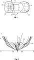
Mit 0 ist in dem schematischen Beispiel für ein Verlustleistungskennfeld die Leistung bei P = 0 gekennzeichnet. Das heißt, der Bereich rechts von der 0 kennzeichnet den motorischen Betrieb des Kraftfahrzeuges
Insbesondere im niedrigen Lastbereich sind hohe Verlustleistungen zu erkennen, die unter anderem auf Losbrechmomente der Elektromotoren
ZITATE ENTHALTEN IN DER BESCHREIBUNG QUOTES INCLUDE IN THE DESCRIPTION
Diese Liste der vom Anmelder aufgeführten Dokumente wurde automatisiert erzeugt und ist ausschließlich zur besseren Information des Lesers aufgenommen. Die Liste ist nicht Bestandteil der deutschen Patent- bzw. Gebrauchsmusteranmeldung. Das DPMA übernimmt keinerlei Haftung für etwaige Fehler oder Auslassungen.This list of the documents listed by the applicant has been generated automatically and is included solely for the better information of the reader. The list is not part of the German patent or utility model application. The DPMA assumes no liability for any errors or omissions.
Zitierte PatentliteraturCited patent literature
- DE 102010020906 A1 [0002] DE 102010020906 A1 [0002]
- EP 1202895 B1 [0003] EP 1202895 B1 [0003]
Claims (7)
Priority Applications (1)
| Application Number | Priority Date | Filing Date | Title |
|---|---|---|---|
| DE201210103292 DE102012103292A1 (en) | 2012-04-17 | 2012-04-17 | Method for operating electrical powertrain of e.g. all-wheel drive motor car, involves determining powers of individual electromotors, such that resultant power dissipations of electromotors is minimized based on power dissipation map |
Applications Claiming Priority (1)
| Application Number | Priority Date | Filing Date | Title |
|---|---|---|---|
| DE201210103292 DE102012103292A1 (en) | 2012-04-17 | 2012-04-17 | Method for operating electrical powertrain of e.g. all-wheel drive motor car, involves determining powers of individual electromotors, such that resultant power dissipations of electromotors is minimized based on power dissipation map |
Publications (1)
| Publication Number | Publication Date |
|---|---|
| DE102012103292A1 true DE102012103292A1 (en) | 2013-10-17 |
Family
ID=49232092
Family Applications (1)
| Application Number | Title | Priority Date | Filing Date |
|---|---|---|---|
| DE201210103292 Pending DE102012103292A1 (en) | 2012-04-17 | 2012-04-17 | Method for operating electrical powertrain of e.g. all-wheel drive motor car, involves determining powers of individual electromotors, such that resultant power dissipations of electromotors is minimized based on power dissipation map |
Country Status (1)
| Country | Link |
|---|---|
| DE (1) | DE102012103292A1 (en) |
Cited By (5)
| Publication number | Priority date | Publication date | Assignee | Title |
|---|---|---|---|---|
| DE102015222690A1 (en) | 2015-11-17 | 2017-05-18 | Volkswagen Aktiengesellschaft | Controlling a drive device of a hybrid vehicle and hybrid vehicle |
| DE102015222692A1 (en) | 2015-11-17 | 2017-05-18 | Volkswagen Aktiengesellschaft | Operating a drive device of a hybrid vehicle and hybrid vehicle |
| DE102015222691A1 (en) | 2015-11-17 | 2017-05-18 | Volkswagen Aktiengesellschaft | Method for controlling a drive device of a hybrid vehicle and hybrid vehicle |
| DE102015222694A1 (en) | 2015-11-17 | 2017-05-18 | Volkswagen Aktiengesellschaft | Operating a drive device of a hybrid vehicle and hybrid vehicle |
| CN108674254A (en) * | 2018-05-11 | 2018-10-19 | 吉林大学 | A kind of multiaxis driving electric vehicle wheel torque distribution method based on driving energy on-line optimization |
Citations (5)
| Publication number | Priority date | Publication date | Assignee | Title |
|---|---|---|---|---|
| EP1202895B1 (en) | 1999-07-29 | 2005-01-26 | Bombardier Transportation GmbH | Method for optimizing energy in a vehicle/train with multple drive units |
| DE102007023164A1 (en) * | 2007-05-16 | 2008-11-20 | Robert Bosch Gmbh | Method for operating a hybrid drive of a vehicle |
| DE102007056302A1 (en) * | 2007-11-22 | 2009-05-28 | Bayerische Motoren Werke Aktiengesellschaft | Hybrid vehicle, has electric machine assigned to one set of drive wheels, another electric machine assigned to one of another set of drive wheels, and third electric machine assigned to other of latter set of drive wheels |
| DE102008052923A1 (en) * | 2007-10-24 | 2009-06-10 | GM Global Technology Operations, Inc., Detroit | Method and system for controlling an inverter in electric drives of vehicles with transmissions with two modes |
| DE102010020906A1 (en) | 2010-05-18 | 2011-11-24 | Gottwald Port Technology Gmbh | Method for energy-optimized operation of a floor-bound heavy-duty transport vehicle with an electric traction drive |
-
2012
- 2012-04-17 DE DE201210103292 patent/DE102012103292A1/en active Pending
Patent Citations (5)
| Publication number | Priority date | Publication date | Assignee | Title |
|---|---|---|---|---|
| EP1202895B1 (en) | 1999-07-29 | 2005-01-26 | Bombardier Transportation GmbH | Method for optimizing energy in a vehicle/train with multple drive units |
| DE102007023164A1 (en) * | 2007-05-16 | 2008-11-20 | Robert Bosch Gmbh | Method for operating a hybrid drive of a vehicle |
| DE102008052923A1 (en) * | 2007-10-24 | 2009-06-10 | GM Global Technology Operations, Inc., Detroit | Method and system for controlling an inverter in electric drives of vehicles with transmissions with two modes |
| DE102007056302A1 (en) * | 2007-11-22 | 2009-05-28 | Bayerische Motoren Werke Aktiengesellschaft | Hybrid vehicle, has electric machine assigned to one set of drive wheels, another electric machine assigned to one of another set of drive wheels, and third electric machine assigned to other of latter set of drive wheels |
| DE102010020906A1 (en) | 2010-05-18 | 2011-11-24 | Gottwald Port Technology Gmbh | Method for energy-optimized operation of a floor-bound heavy-duty transport vehicle with an electric traction drive |
Cited By (9)
| Publication number | Priority date | Publication date | Assignee | Title |
|---|---|---|---|---|
| DE102015222690A1 (en) | 2015-11-17 | 2017-05-18 | Volkswagen Aktiengesellschaft | Controlling a drive device of a hybrid vehicle and hybrid vehicle |
| DE102015222692A1 (en) | 2015-11-17 | 2017-05-18 | Volkswagen Aktiengesellschaft | Operating a drive device of a hybrid vehicle and hybrid vehicle |
| DE102015222691A1 (en) | 2015-11-17 | 2017-05-18 | Volkswagen Aktiengesellschaft | Method for controlling a drive device of a hybrid vehicle and hybrid vehicle |
| DE102015222694A1 (en) | 2015-11-17 | 2017-05-18 | Volkswagen Aktiengesellschaft | Operating a drive device of a hybrid vehicle and hybrid vehicle |
| WO2017084888A1 (en) | 2015-11-17 | 2017-05-26 | Volkswagen Aktiengesellschaft | Operation of a drive apparatus of a hybrid vehicle and hybrid vehicle |
| WO2017084887A1 (en) | 2015-11-17 | 2017-05-26 | Volkswagen Aktiengesellschaft | Method for controlling a drive device of a hybrid vehicle and hybrid vehicle |
| WO2017084889A1 (en) | 2015-11-17 | 2017-05-26 | Volkswagen Aktiengesellschaft | Operating a drive device of a hybrid vehicle and hybrid vehicle |
| US10525968B2 (en) | 2015-11-17 | 2020-01-07 | Volkswagen Aktiengesellschaft | Method for controlling a drive device of a hybrid vehicle and hybrid vehicle |
| CN108674254A (en) * | 2018-05-11 | 2018-10-19 | 吉林大学 | A kind of multiaxis driving electric vehicle wheel torque distribution method based on driving energy on-line optimization |
Similar Documents
| Publication | Publication Date | Title |
|---|---|---|
| DE102013226472B4 (en) | POWER TRANSMISSION SYSTEM FOR A HYBRID VEHICLE | |
| DE102009050957B4 (en) | mixed hybrid | |
| DE102015222692A1 (en) | Operating a drive device of a hybrid vehicle and hybrid vehicle | |
| EP2323862B1 (en) | Method and device for operating a hybrid drive for a vehicle | |
| DE102009056366A1 (en) | Drive system for a motor vehicle | |
| DE102015222690A1 (en) | Controlling a drive device of a hybrid vehicle and hybrid vehicle | |
| DE102010015423A1 (en) | Drive device for a four-wheel drive vehicle | |
| EP2289751B1 (en) | Hybrid powertrain for a motor vehicle and method for operating same | |
| DE102007038585A1 (en) | Method for load point shift in hybrid operation in a parallel hybrid vehicle | |
| DE102008030581A1 (en) | Drive train for a motor vehicle and method for operating a drive train of a motor vehicle | |
| DE102017211978A1 (en) | Method for operating a drive train for a motor vehicle, in particular for a motor vehicle, and drive train for a motor vehicle | |
| DE102014004522B4 (en) | Drive device for a motor vehicle | |
| DE102020119290A1 (en) | Electrical drive device for a vehicle | |
| DE102010031156A1 (en) | Power train for electric car, has electric machines respectively coupled as respective traction drives with translation parts over gear box and clutch unit, where one of electric machines is formed as auxiliary drive for auxiliary unit | |
| DE102010046048A1 (en) | driving device | |
| DE102011050986A1 (en) | Motor vehicle with transversely arranged engine having drivetrain | |
| DE102006059005B4 (en) | Hybrid drive for vehicles | |
| DE102012103292A1 (en) | Method for operating electrical powertrain of e.g. all-wheel drive motor car, involves determining powers of individual electromotors, such that resultant power dissipations of electromotors is minimized based on power dissipation map | |
| DE102019129670A1 (en) | HYBRID AXLE DRIVE WITH TORQUE VECTORING | |
| AT522931A1 (en) | ELECTRICALLY DRIVEN AXLE ARRANGEMENT FOR A VEHICLE | |
| DE102007004458A1 (en) | Hybrid drive arrangement for vehicle with drive section, has combustion engine and two electrical machines, which are operated as motor and generator, and brake is provided for producing supporting moment | |
| DE102018116010A1 (en) | ELECTRIC DRIVING UNIT WITH TWO TRANSLATION RATIO | |
| DE102016221796A1 (en) | Hybrid transmission and hybrid powertrain | |
| DE102009050956A1 (en) | Drive strand for hybrid vehicle, has two combustion engines and two electro-machines for optional drive of wheels of hybrid vehicle | |
| DE102007056302A1 (en) | Hybrid vehicle, has electric machine assigned to one set of drive wheels, another electric machine assigned to one of another set of drive wheels, and third electric machine assigned to other of latter set of drive wheels |
Legal Events
| Date | Code | Title | Description |
|---|---|---|---|
| R163 | Identified publications notified | ||
| R012 | Request for examination validly filed |