DE102012024968A1 - Crankshaft bearing for wear-resistant internal combustion engine of motor car, has cylinder head screws arranged in bearing block screws through contact surface that is provided at region around block screws inclined to cylinder head screws - Google Patents
Crankshaft bearing for wear-resistant internal combustion engine of motor car, has cylinder head screws arranged in bearing block screws through contact surface that is provided at region around block screws inclined to cylinder head screws Download PDFInfo
- Publication number
- DE102012024968A1 DE102012024968A1 DE201210024968 DE102012024968A DE102012024968A1 DE 102012024968 A1 DE102012024968 A1 DE 102012024968A1 DE 201210024968 DE201210024968 DE 201210024968 DE 102012024968 A DE102012024968 A DE 102012024968A DE 102012024968 A1 DE102012024968 A1 DE 102012024968A1
- Authority
- DE
- Germany
- Prior art keywords
- bearing
- cylinder head
- screws
- contact surface
- internal combustion
- Prior art date
- Legal status (The legal status is an assumption and is not a legal conclusion. Google has not performed a legal analysis and makes no representation as to the accuracy of the status listed.)
- Withdrawn
Links
- 238000002485 combustion reaction Methods 0.000 title claims description 25
- 230000015572 biosynthetic process Effects 0.000 claims description 2
- 238000000926 separation method Methods 0.000 description 2
- BUHVIAUBTBOHAG-FOYDDCNASA-N (2r,3r,4s,5r)-2-[6-[[2-(3,5-dimethoxyphenyl)-2-(2-methylphenyl)ethyl]amino]purin-9-yl]-5-(hydroxymethyl)oxolane-3,4-diol Chemical compound COC1=CC(OC)=CC(C(CNC=2C=3N=CN(C=3N=CN=2)[C@H]2[C@@H]([C@H](O)[C@@H](CO)O2)O)C=2C(=CC=CC=2)C)=C1 BUHVIAUBTBOHAG-FOYDDCNASA-N 0.000 description 1
- 229910052782 aluminium Inorganic materials 0.000 description 1
- XAGFODPZIPBFFR-UHFFFAOYSA-N aluminium Chemical compound [Al] XAGFODPZIPBFFR-UHFFFAOYSA-N 0.000 description 1
- 238000010276 construction Methods 0.000 description 1
- 230000001419 dependent effect Effects 0.000 description 1
- 238000011161 development Methods 0.000 description 1
- 230000018109 developmental process Effects 0.000 description 1
- 230000000977 initiatory effect Effects 0.000 description 1
- 229910052751 metal Inorganic materials 0.000 description 1
- 239000002184 metal Substances 0.000 description 1
- 238000005096 rolling process Methods 0.000 description 1
Images
Classifications
-
- F—MECHANICAL ENGINEERING; LIGHTING; HEATING; WEAPONS; BLASTING
- F02—COMBUSTION ENGINES; HOT-GAS OR COMBUSTION-PRODUCT ENGINE PLANTS
- F02F—CYLINDERS, PISTONS OR CASINGS, FOR COMBUSTION ENGINES; ARRANGEMENTS OF SEALINGS IN COMBUSTION ENGINES
- F02F7/00—Casings, e.g. crankcases
- F02F7/0043—Arrangements of mechanical drive elements
- F02F7/0053—Crankshaft bearings fitted in the crankcase
-
- F—MECHANICAL ENGINEERING; LIGHTING; HEATING; WEAPONS; BLASTING
- F16—ENGINEERING ELEMENTS AND UNITS; GENERAL MEASURES FOR PRODUCING AND MAINTAINING EFFECTIVE FUNCTIONING OF MACHINES OR INSTALLATIONS; THERMAL INSULATION IN GENERAL
- F16C—SHAFTS; FLEXIBLE SHAFTS; ELEMENTS OR CRANKSHAFT MECHANISMS; ROTARY BODIES OTHER THAN GEARING ELEMENTS; BEARINGS
- F16C7/00—Connecting-rods or like links pivoted at both ends; Construction of connecting-rod heads
- F16C7/02—Constructions of connecting-rods with constant length
- F16C7/023—Constructions of connecting-rods with constant length for piston engines, pumps or the like
-
- F—MECHANICAL ENGINEERING; LIGHTING; HEATING; WEAPONS; BLASTING
- F16—ENGINEERING ELEMENTS AND UNITS; GENERAL MEASURES FOR PRODUCING AND MAINTAINING EFFECTIVE FUNCTIONING OF MACHINES OR INSTALLATIONS; THERMAL INSULATION IN GENERAL
- F16C—SHAFTS; FLEXIBLE SHAFTS; ELEMENTS OR CRANKSHAFT MECHANISMS; ROTARY BODIES OTHER THAN GEARING ELEMENTS; BEARINGS
- F16C9/00—Bearings for crankshafts or connecting-rods; Attachment of connecting-rods
- F16C9/04—Connecting-rod bearings; Attachments thereof
-
- F—MECHANICAL ENGINEERING; LIGHTING; HEATING; WEAPONS; BLASTING
- F02—COMBUSTION ENGINES; HOT-GAS OR COMBUSTION-PRODUCT ENGINE PLANTS
- F02F—CYLINDERS, PISTONS OR CASINGS, FOR COMBUSTION ENGINES; ARRANGEMENTS OF SEALINGS IN COMBUSTION ENGINES
- F02F7/00—Casings, e.g. crankcases
- F02F7/006—Camshaft or pushrod housings
- F02F2007/0063—Head bolts; Arrangements of cylinder head bolts
Landscapes
- Engineering & Computer Science (AREA)
- General Engineering & Computer Science (AREA)
- Mechanical Engineering (AREA)
- Chemical & Material Sciences (AREA)
- Combustion & Propulsion (AREA)
- Shafts, Cranks, Connecting Bars, And Related Bearings (AREA)
- Cylinder Crankcases Of Internal Combustion Engines (AREA)
Abstract
Description
Die Erfindung betrifft eine Kurbelwellenlagerung für eine Brennkraftmaschine nach dem Oberbegriff des Anspruchs 1 und eine Brennkraftmaschine nach dem Anspruch 3.The invention relates to a crankshaft bearing for an internal combustion engine according to the preamble of claim 1 and an internal combustion engine according to claim 3.
Aus der
Weiter sind bereits Kurbelwellenlagerungen für Brennkraftmaschinen, mit zwei Zylinderkopfschrauben, die in das Lagerstuhloberteil eingreifen, bekannt.Next crankshaft bearings for internal combustion engines, with two cylinder head bolts, which engage in the Lagerstuhloberteil known.
Der Erfindung liegt insbesondere die Aufgabe zugrunde, eine verschleißarme Brennkraftmaschine bereitzustellen, die eine Kurbelwellenlagerung mit einer hohen Festigkeit aufweist. Diese Aufgabe wird durch eine erfindungsgemäße Kurbelwellenlagerung entsprechend dem Anspruch 1 und eine Brennkraftmaschine entsprechend dem Anspruch 3 gelöst. Weiterbildungen der Erfindung ergeben sich aus den abhängigen Ansprüchen.The invention is in particular the object of providing a low-wear internal combustion engine, which has a crankshaft bearing with a high strength. This object is achieved by a crankshaft bearing according to the invention according to claim 1 and an internal combustion engine according to claim 3. Further developments of the invention will become apparent from the dependent claims.
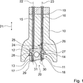
Die Erfindung geht aus von einer Kurbelwellenlagerung für eine Brennkraftmaschine eines Kraftfahrzeugs, mit einem zumindest zweiteiligen, separat zu einem Kurbelgehäuse ausgebildeten Lagerstuhl, der ein Lagerstuhloberteil und ein Lagerstuhlunterteil, die sich in einer Kontaktfläche gegenseitig berühren, aufweist, mit zumindest einer Zylinderkopfschraube, die in das Lagerstuhloberteil zumindest eingreift, und mit zumindest einer schräg zur Zylinderkopfschraube angeordneten Lagerstuhlschraube, die in das Lagerstuhloberteil und in das Lagerstuhlunterteil zumindest eingreift und die Kontaktfläche durchquert.The invention relates to a crankshaft bearing for an internal combustion engine of a motor vehicle, having an at least two-part, separately formed to a crankcase bearing block having a Lagerstuhloberteil and a Lagerstuhlunterteil, which touch each other in a contact surface, with at least one cylinder head bolt, which in the Lagerstuhloberteil at least engages, and at least one arranged obliquely to the cylinder head bolt bearing bolt, which at least engages in the Lagerstuhloberteil and in the bearing block base and passes through the contact surface.
Es wird vorgeschlagen, dass die Kontaktfläche zumindest in einem Bereich um die Lagerstuhlschraube schräg zur Zylinderkopfschraube angeordnet ist. Dadurch kann ein Abstand zwischen der zumindest einen, in das Lagerstuhloberteil eingreifenden Zylinderkopfschraube und der zumindest einen, in das Lagerstuhloberteil eingreifenden Lagerstuhlschraube vergrößert und eine Einleitung einer durch die Lagerstuhlschraube resultierenden Querkraft zumindest reduziert werden, wodurch bei gleichzeitiger Vermeidung eines Verzugs des Kurbelgehäuses ein ausreichender Abstand zwischen der Zylinderkopfschraube und der Lagerstuhlschraube und eine Reduzierung einer Belastung des Lagerstuhls realisiert werden kann. Dabei kann durch die Vermeidung des Verzugs des Kurbelgehäuses eine Reibung und ein Ölverbrauch gering gehalten werden und durch die schräge Anordnung der Lagerstuhlschraube und der Kontaktfläche relativ zu der Zylinderkopfschraube eine Festigkeit der Kurbelwellenlagerung erhöht werden. Dadurch kann eine verschleißarme Brennkraftmaschine, die eine Kurbelwellenlagerung mit einer hohen Festigkeit aufweist, bereitgestellt werden. Unter einer „Lagerstuhlschraube, die schräg zur Zylinderkopfschraube angeordnet ist”, soll insbesondere verstanden werden, dass eine Längsachse der Lagerstuhlschraube und eine Längsachse der Zylinderkopfschraube sich in einem Punkt schneiden und/oder mit einem Winkel ungleich Null, insbesondere mit einem Winkel zwischen 0 und 90°, zueinander orientiert sind. Unter einer „Kontaktfläche, die schräg zur Zylinderkopfschraube angeordnet ist”, soll insbesondere verstanden werden, das die Kontaktfläche zumindest eine Normale aufweist, die bei einer Verlängerung die Längsachse der Zylinderkopfschraube in einem Punkt schneidet und/oder die mit einem Winkel ungleich Null, insbesondere in einem Winkel zwischen 0 und 90°, zur Längsachse der Zylinderkopfschraube orientiert ist. Unter „vorgesehen” soll insbesondere speziell ausgelegt, ausgestattet und/oder angeordnet verstanden werden.It is proposed that the contact surface is arranged at least in an area around the bearing bolt obliquely to the cylinder head screw. As a result, a distance between the at least one cylinder head screw engaging in the bearing block upper part and the at least one bearing block bolt engaging in the bearing block upper part can be increased and initiation of a transverse force resulting from the bearing block screw can be at least reduced, thereby avoiding distortion of the crankcase the cylinder head bolt and the bearing bolt and a reduction of a load of the bearing block can be realized. It can be kept low by avoiding the delay of the crankcase friction and oil consumption and by the oblique arrangement of the bearing bolt and the contact surface relative to the cylinder head bolt strength of the crankshaft bearing can be increased. Thereby, a low-wear internal combustion engine having a high-strength crankshaft bearing can be provided. Under a "bearing bolt, which is arranged obliquely to the cylinder head screw" should be understood in particular that a longitudinal axis of the bearing bolt and a longitudinal axis of the cylinder head screw intersect at a point and / or at an angle not equal to zero, in particular at an angle between 0 and 90 °, are oriented to each other. A "contact surface which is arranged obliquely to the cylinder head screw" is to be understood in particular as meaning that the contact surface has at least one normal which intersects the longitudinal axis of the cylinder head screw in one point during an extension and / or at an angle not equal to zero, in particular an angle between 0 and 90 °, oriented to the longitudinal axis of the cylinder head screw. By "provided" is to be understood in particular specially designed, equipped and / or arranged.
Zur Realisierung einer besonders hohen Festigkeit ist es insbesondere vorteilhaft, wenn die Kontaktfläche zumindest in dem Bereich um die Lagerstuhlschraube zumindest im Wesentlichen senkrecht zu der Lagerstuhlschraube angeordnet ist. Dadurch kann die Kontaktfläche um den selben Winkel schräg gestellt werden wie die Lagerstuhlschraube, wodurch die Einleitung der Querkraft durch die Lagerstuhlschrauben vermieden werden kann. Darunter, dass „die Kontaktfläche zumindest im Wesentlichen senkrecht zu der Lagerstuhlschraube angeordnet ist” soll insbesondere verstanden werden, dass die zumindest eine Normale der Kontaktfläche und die Längsachse der Lagerstuhlschraube zumindest im Wesentlichen parallel zueinander orientiert sind. Unter „im Wesentlichen” soll in diesem Zusammenhang insbesondere eine Abweichung von einer senkrechten oder einer parallelen Orientierung verstanden werden, die maximal 20 Grad, vorteilhaft maximal 10 Grad und besonders vorteilhaft maximal 5 Grad beträgt.To realize a particularly high strength, it is particularly advantageous if the contact surface is arranged at least in the area around the bearing bolt at least substantially perpendicular to the bearing bolt. As a result, the contact surface can be inclined by the same angle as the bearing bolt, whereby the introduction of the lateral force can be avoided by the bearing bolts. By the fact that "the contact surface is arranged at least substantially perpendicular to the bearing bolt" is to be understood in particular that the at least one normal of the contact surface and the longitudinal axis of the bearing screw are oriented at least substantially parallel to each other. In this context, "essentially" is to be understood as meaning, in particular, a deviation from a vertical or a parallel orientation which is at most 20 degrees, advantageously at most 10 degrees, and particularly advantageously at most 5 degrees.
Weiter wird eine Brennkraftmaschine eines Kraftfahrzeugs mit einer erfindungsgemäßen Kurbelwellenlagerung vorgeschlagen, wodurch eine verschleißarme Brennkraftmaschine mit einer stabilen Kurbelwellenlagerung bereitgestellt werden kann.Further, an internal combustion engine of a motor vehicle is proposed with a crankshaft bearing according to the invention, whereby a low-wear internal combustion engine with a stable crankshaft bearing can be provided.
Insbesondere ist es vorteilhaft, wenn die Kurbelwellenlagerung zur Ausbildung eines geschränkten Kurbeltriebs vorgesehen ist, wodurch eine Laufruhe, insbesondere im Leerlauf, verbessert werden kann. Ferner kann dadurch eine kompakte, verbrauchsarme Brennkraftmaschine bereitgestellt werden. Unter einem „geschränkten Kurbeltrieb” soll insbesondere verstanden werden, dass zwischen einer Mitte der Kurbelwelle und einer Mitte von Kolben der Brennkraftmaschine ein Versatz vorliegt.In particular, it is advantageous if the crankshaft bearing is provided for the formation of a limited crank mechanism, whereby a smoothness, especially at idle, can be improved. Furthermore, this can result in a compact, low-consumption internal combustion engine are provided. A "restricted crank mechanism" is to be understood in particular as meaning that there is an offset between a center of the crankshaft and a center of piston of the internal combustion engine.
Weitere Vorteile ergeben sich aus der folgenden Figurenbeschreibung. In der einzigen Figur ist ein Ausführungsbeispiel der Erfindung dargestellt. Die Figur, die Figurenbeschreibung und die Ansprüche enthalten zahlreiche Merkmale in Kombination. Der Fachmann wird die Merkmale zweckmäßigerweise auch einzeln betrachten und zu sinnvollen weiteren Kombinationen zusammenfassen.Further advantages will become apparent from the following description of the figures. In the single figure, an embodiment of the invention is shown. The figure, the description of the figures and the claims contain numerous features in combination. The person skilled in the art will expediently also consider the features individually and combine them into meaningful further combinations.
Die Kurbelwellenlagerung
Zur Befestigung des Lagerstuhloberteils
Zur Befestigung des Lagerstuhlunterteils
Zur Erhöhung einer Festigkeit des Lagerstuhls
Um zu vermeiden, dass durch die Verschraubung mittels den Lagerstuhlschrauben
Eine Anliegefläche
BezugszeichenlisteLIST OF REFERENCE NUMBERS
- 1010
- Kurbelgehäusecrankcase
- 1111
- Lagerstuhlbearing block
- 1212
- LagerstuhloberteilBearing bracket shell
- 1313
- LagerstuhlunterteilCamp chair base
- 1414
- Kontaktflächecontact area
- 1515
- ZylinderkopfschraubeCylinderhead screw
- 1616
- ZylinderkopfschraubeCylinderhead screw
- 1717
- LagerstuhlschraubeBearing bracket screw
- 1818
- LagerstuhlschraubeBearing bracket screw
- 1919
- Zylinderkopfcylinder head
- 2020
- Kurbelwellenlagerungcrankshaft bearing
- 2121
- Hochachsevertical axis
- 2222
- Längsachselongitudinal axis
- 2323
- Längsachselongitudinal axis
- 2424
- Längsachselongitudinal axis
- 2525
- Längsachselongitudinal axis
- 2626
- Winkelangle
- 2727
- Winkelangle
- 2828
- Winkelangle
- 2929
- Schnittpunktintersection
- 3030
- Schnittpunktintersection
- 3131
- Anliegeflächebearing surface
ZITATE ENTHALTEN IN DER BESCHREIBUNG QUOTES INCLUDE IN THE DESCRIPTION
Diese Liste der vom Anmelder aufgeführten Dokumente wurde automatisiert erzeugt und ist ausschließlich zur besseren Information des Lesers aufgenommen. Die Liste ist nicht Bestandteil der deutschen Patent- bzw. Gebrauchsmusteranmeldung. Das DPMA übernimmt keinerlei Haftung für etwaige Fehler oder Auslassungen.This list of the documents listed by the applicant has been generated automatically and is included solely for the better information of the reader. The list is not part of the German patent or utility model application. The DPMA assumes no liability for any errors or omissions.
Zitierte PatentliteraturCited patent literature
- DE 1251587 B [0002] DE 1251587 B [0002]
Claims (4)
Priority Applications (1)
| Application Number | Priority Date | Filing Date | Title |
|---|---|---|---|
| DE201210024968 DE102012024968A1 (en) | 2012-12-20 | 2012-12-20 | Crankshaft bearing for wear-resistant internal combustion engine of motor car, has cylinder head screws arranged in bearing block screws through contact surface that is provided at region around block screws inclined to cylinder head screws |
Applications Claiming Priority (1)
| Application Number | Priority Date | Filing Date | Title |
|---|---|---|---|
| DE201210024968 DE102012024968A1 (en) | 2012-12-20 | 2012-12-20 | Crankshaft bearing for wear-resistant internal combustion engine of motor car, has cylinder head screws arranged in bearing block screws through contact surface that is provided at region around block screws inclined to cylinder head screws |
Publications (1)
| Publication Number | Publication Date |
|---|---|
| DE102012024968A1 true DE102012024968A1 (en) | 2014-06-26 |
Family
ID=50878273
Family Applications (1)
| Application Number | Title | Priority Date | Filing Date |
|---|---|---|---|
| DE201210024968 Withdrawn DE102012024968A1 (en) | 2012-12-20 | 2012-12-20 | Crankshaft bearing for wear-resistant internal combustion engine of motor car, has cylinder head screws arranged in bearing block screws through contact surface that is provided at region around block screws inclined to cylinder head screws |
Country Status (1)
| Country | Link |
|---|---|
| DE (1) | DE102012024968A1 (en) |
Cited By (1)
| Publication number | Priority date | Publication date | Assignee | Title |
|---|---|---|---|---|
| GB2541014A (en) * | 2015-08-06 | 2017-02-08 | Gm Global Tech Operations Llc | Internal combustion engine element arrangement |
Citations (1)
| Publication number | Priority date | Publication date | Assignee | Title |
|---|---|---|---|---|
| DE1251587B (en) | 1967-10-05 |
-
2012
- 2012-12-20 DE DE201210024968 patent/DE102012024968A1/en not_active Withdrawn
Patent Citations (1)
| Publication number | Priority date | Publication date | Assignee | Title |
|---|---|---|---|---|
| DE1251587B (en) | 1967-10-05 |
Cited By (1)
| Publication number | Priority date | Publication date | Assignee | Title |
|---|---|---|---|---|
| GB2541014A (en) * | 2015-08-06 | 2017-02-08 | Gm Global Tech Operations Llc | Internal combustion engine element arrangement |
Similar Documents
| Publication | Publication Date | Title |
|---|---|---|
| DE2221804C2 (en) | Crankcase for multi-cylinder piston machines | |
| DE102007061124B4 (en) | Design of the upper chamfer of a piston to reduce noise and friction | |
| EP2140127A1 (en) | Piston for an internal combustion engine | |
| DE112015004765B4 (en) | Cylinder block and engine provided therewith | |
| WO2010017808A2 (en) | Piston for an internal combustion engine | |
| DE102008053423A1 (en) | oil baffle | |
| EP2823166A1 (en) | Cast light metal piston, in particular an aluminium piston | |
| DE102017209729B4 (en) | Battery case and vehicle with such a battery case | |
| DE102012024968A1 (en) | Crankshaft bearing for wear-resistant internal combustion engine of motor car, has cylinder head screws arranged in bearing block screws through contact surface that is provided at region around block screws inclined to cylinder head screws | |
| DE102007037461A1 (en) | Internal combustion engine e.g. skirt engine, has cylinder housing lower part comprising separate bearing cap of crankshaft bearing, which is connected with cylinder crankcase by angular screw connection | |
| DE102010051825A1 (en) | Internal combustion engine mounted on vehicle e.g. car, has supplementary portion which is in form of nut that is secured at connecting rod through screw | |
| EP3371443A1 (en) | Optimized hub support | |
| DE102015210597A1 (en) | Reciprocating engine and motor vehicle | |
| DE102011108947A1 (en) | Counterweight attached to connecting rod in internal combustion engine, has auxiliary element with ca, which is inserted into groove of main structure, and is secured at connecting rod by screw | |
| DE102015005576B4 (en) | Internal combustion engine with variable compression ratio | |
| DE102018209455A1 (en) | Cast piston for an internal combustion engine, made of an iron-based material | |
| DE102011113525A1 (en) | Method for increasing effective pressure in piston combustion engine of passenger car, involves forming recess by arrangement of part relative to axles, where moment of excluding material for formation of recess and moment of part are same | |
| DE102019124376A1 (en) | Pistons for internal combustion engines | |
| DE102012000884A1 (en) | Engine block for combustion engine of motor car, has bearing support comprising mounting openings for assembling to threaded sleeves, where mounting openings are accessible in mounted state of crankcase and bearing cover | |
| DE102006016777B4 (en) | Vehicle of the type with a saddle with high-pressure fuel pump | |
| DE102010006958A1 (en) | Method for assembling piston and connecting rod in cylinder of cylinder crankcase of combustion engine, involves moving back piston and connecting rod toward crank space within cylinder, until large connecting rod eye is fixed at crankshaft | |
| DE102016113682A1 (en) | Cylinder crankcase in lightweight construction for internal combustion engines | |
| DE102010047972A1 (en) | Piston device for lifting cylinder combustion engine of motor car, has connecting ranging guide unit which forms closures with attachment element of connecting ranging unit | |
| DE536131C (en) | Automatic valve | |
| DE102017102124A1 (en) | Piston of an internal combustion engine |
Legal Events
| Date | Code | Title | Description |
|---|---|---|---|
| R119 | Application deemed withdrawn, or ip right lapsed, due to non-payment of renewal fee |