DE102012024924A1 - Device for driving piston pump, such as high-pressure pumps for common rail system, of motor vehicle, has piston pump unit which has working area limiting piston, where crank drive is formed for driving piston - Google Patents
Device for driving piston pump, such as high-pressure pumps for common rail system, of motor vehicle, has piston pump unit which has working area limiting piston, where crank drive is formed for driving piston Download PDFInfo
- Publication number
- DE102012024924A1 DE102012024924A1 DE201210024924 DE102012024924A DE102012024924A1 DE 102012024924 A1 DE102012024924 A1 DE 102012024924A1 DE 201210024924 DE201210024924 DE 201210024924 DE 102012024924 A DE102012024924 A DE 102012024924A DE 102012024924 A1 DE102012024924 A1 DE 102012024924A1
- Authority
- DE
- Germany
- Prior art keywords
- piston
- piston pump
- driving
- crank drive
- pump
- Prior art date
- Legal status (The legal status is an assumption and is not a legal conclusion. Google has not performed a legal analysis and makes no representation as to the accuracy of the status listed.)
- Withdrawn
Links
- 239000000314 lubricant Substances 0.000 claims description 10
- 239000000446 fuel Substances 0.000 claims description 8
- 238000002485 combustion reaction Methods 0.000 claims description 5
- 238000002347 injection Methods 0.000 claims description 5
- 239000007924 injection Substances 0.000 claims description 5
- 238000005096 rolling process Methods 0.000 description 4
- 230000006835 compression Effects 0.000 description 3
- 238000007906 compression Methods 0.000 description 3
- 238000011161 development Methods 0.000 description 2
- 230000018109 developmental process Effects 0.000 description 2
- 239000010687 lubricating oil Substances 0.000 description 2
- 238000005461 lubrication Methods 0.000 description 2
- BUHVIAUBTBOHAG-FOYDDCNASA-N (2r,3r,4s,5r)-2-[6-[[2-(3,5-dimethoxyphenyl)-2-(2-methylphenyl)ethyl]amino]purin-9-yl]-5-(hydroxymethyl)oxolane-3,4-diol Chemical compound COC1=CC(OC)=CC(C(CNC=2C=3N=CN(C=3N=CN=2)[C@H]2[C@@H]([C@H](O)[C@@H](CO)O2)O)C=2C(=CC=CC=2)C)=C1 BUHVIAUBTBOHAG-FOYDDCNASA-N 0.000 description 1
- 230000005540 biological transmission Effects 0.000 description 1
- 230000015572 biosynthetic process Effects 0.000 description 1
- 238000004891 communication Methods 0.000 description 1
- 230000001419 dependent effect Effects 0.000 description 1
- 230000002996 emotional effect Effects 0.000 description 1
- 239000002828 fuel tank Substances 0.000 description 1
- 239000007788 liquid Substances 0.000 description 1
- 238000004519 manufacturing process Methods 0.000 description 1
- 239000000463 material Substances 0.000 description 1
- 239000000203 mixture Substances 0.000 description 1
- 239000003921 oil Substances 0.000 description 1
- 239000002245 particle Substances 0.000 description 1
- 238000005086 pumping Methods 0.000 description 1
- 239000000243 solution Substances 0.000 description 1
Images
Classifications
-
- F—MECHANICAL ENGINEERING; LIGHTING; HEATING; WEAPONS; BLASTING
- F04—POSITIVE - DISPLACEMENT MACHINES FOR LIQUIDS; PUMPS FOR LIQUIDS OR ELASTIC FLUIDS
- F04B—POSITIVE-DISPLACEMENT MACHINES FOR LIQUIDS; PUMPS
- F04B1/00—Multi-cylinder machines or pumps characterised by number or arrangement of cylinders
- F04B1/04—Multi-cylinder machines or pumps characterised by number or arrangement of cylinders having cylinders in star- or fan-arrangement
- F04B1/0404—Details or component parts
- F04B1/0408—Pistons
-
- F—MECHANICAL ENGINEERING; LIGHTING; HEATING; WEAPONS; BLASTING
- F04—POSITIVE - DISPLACEMENT MACHINES FOR LIQUIDS; PUMPS FOR LIQUIDS OR ELASTIC FLUIDS
- F04B—POSITIVE-DISPLACEMENT MACHINES FOR LIQUIDS; PUMPS
- F04B1/00—Multi-cylinder machines or pumps characterised by number or arrangement of cylinders
- F04B1/04—Multi-cylinder machines or pumps characterised by number or arrangement of cylinders having cylinders in star- or fan-arrangement
- F04B1/0404—Details or component parts
- F04B1/0413—Cams
-
- F—MECHANICAL ENGINEERING; LIGHTING; HEATING; WEAPONS; BLASTING
- F04—POSITIVE - DISPLACEMENT MACHINES FOR LIQUIDS; PUMPS FOR LIQUIDS OR ELASTIC FLUIDS
- F04B—POSITIVE-DISPLACEMENT MACHINES FOR LIQUIDS; PUMPS
- F04B1/00—Multi-cylinder machines or pumps characterised by number or arrangement of cylinders
- F04B1/04—Multi-cylinder machines or pumps characterised by number or arrangement of cylinders having cylinders in star- or fan-arrangement
- F04B1/0404—Details or component parts
- F04B1/0426—Arrangements for pressing the pistons against the actuated cam; Arrangements for connecting the pistons to the actuated cam
Landscapes
- Engineering & Computer Science (AREA)
- Mechanical Engineering (AREA)
- General Engineering & Computer Science (AREA)
- Reciprocating Pumps (AREA)
Abstract
Die Erfindung betrifft eine Vorrichtung zum Antrieb einer Kolbenpumpe mit wenigstens einer Kolbenpumpeneinheit, die einen Arbeitsraum begrenzenden Kolben aufweist, mit einem Kurbelantrieb zum Antreiben des Kolbens, dadurch gekennzeichnet, dass zwischen dem Kurbelantrieb und dem Kolben ein auf einer rotierend antreibbaren Antriebswelle mit einer Exzentrizität angeordnetes Exzenterelement vorgesehen ist, das bezüglich des Kurbelantriebs in der Weise rotierend gelagert ist, dass das Exzenterelement auf zumindest einem Teil der Kolbenpumpe derart abrollt, dass eine Kolbenbewegung verursacht wird.The invention relates to a device for driving a piston pump with at least one piston pump unit which has a piston which delimits a working space, with a crank drive for driving the piston, characterized in that an eccentric element arranged on a rotatingly drivable drive shaft with an eccentricity is arranged between the crank drive and the piston is provided which is rotatably mounted with respect to the crank drive in such a way that the eccentric element rolls on at least part of the piston pump in such a way that a piston movement is caused.
Description
Die Erfindung betrifft eine Vorrichtung zum Antrieb einer Kolbenpumpe mit den Merkmalen gemäß des Oberbegriffes des Anspruchs 1. Eine Voraussetzung für eine effiziente Verbrennung ist eine gute Gemischbildung. Dabei spielt das Einspritzsystem eine zentrale Rolle. Der Kraftstoff muss in der richtigen Menge, zum richtigen Zeitpunkt und mit einem hohen Druck eingespritzt werden. Für die Druckerzeugung ist eine Hochdruckpumpe vorgesehen.The invention relates to a device for driving a piston pump with the features according to the preamble of
Aus dem Dokument
In dem Dokument
Von diesem Hintergrund ist die Aufgabe der vorliegenden Erfindung die Hochdruckpumpe für sehr hohe Förderdrucke bereitzustellen, deren Herstellungskosten möglichst gering sind und die hohe Anforderungen an die Lebensdauer erfüllt.Against this background, the object of the present invention is to provide the high pressure pump for very high discharge pressures, the production costs are as low as possible and meets the high life requirements.
Diese Aufgabe wird erfindungsgemäß durch eine Vorrichtung mit den Merkmalen des unabhängigen Anspruchs 1 gelöst. Erfindungsgemäß wird eine Vorrichtung zum Antrieb einer Kolbenpumpe mit wenigstens einer Kolbenpumpeneinheit vorgeschlagen, die einen Arbeitsraum begrenzenden Kolben aufweist, mit einem Kurbelantrieb zum Antreiben des Kolbens, wobei zwischen dem Kurbelantrieb und dem Kolben ein auf einer rotierend antreibbaren Antriebswelle mit einer Exzentrizität angeordnetes Exzenterelement vorgesehen ist, das bezüglich des Kurbelantriebs in der Weise rotierend gelagert ist, dass das Exzenterelement auf zumindest einem Teil der Kolbenpumpe derart abrollt, dass eine Kolbenbewegung verursacht wird. Teil kann Teil einer Außenfläche sein.This object is achieved by a device having the features of
Vorteilhafte Weiterbildungen der Erfindung sind in den abhängigen Ansprüchen charakterisiert.Advantageous developments of the invention are characterized in the dependent claims.
Die erfindungsgemäße Kolbenpumpe kann insbesondere eine hubringlose Kolbenpumpe sein. Durch das Abrollen des Exzenterelementes auf der Antriebswelle ist die Kontaktfläche zwischen dem Teil der Kolbenpumpe und dem Exzenterelement deutlich weniger belastet als beim herkömmlichen Gleiten. Es kommt zu einem wesentlich verringerten Verschleiß der Kolbenführung. Ein Vorteil der erfindungsgemäßen Vorrichtung besteht damit darin, dass eine Drehzahl der Kolbenpumpe gemindert werden kann und die Spannung, die in der Mitte der Berührungsfläche des Exzenterelementes und des Teils der Kolbenpumpe entsteht, klein gehalten werden kann. Dadurch ist diese Kontaktlinie unanfälliger gegenüber jeglichen Schmutzpartikeln. Durch das Abrollen wird ebenfalls ein gewollter Schlupf zwischen dem Exzenterelement und dem Teil der Kolbenpumpe, auf dem es abrollt, verursacht. Durch den Schlupf wird die Kontaktfläche immer Stück für Stück weiterverschoben, so dass das gesamte Exzenterelement benutzt werden kann und damit gleichmäßig beansprucht wird. Dieser Schlupf kann über die Restfederkraft im unteren Totpunkt beeinflusst werden. Bevorzugt ist eine Ausführungsform der Vorrichtung, wonach ein Teil der Kolbenpumpe der Kolben selbst oder ein Stößel ist. In bevorzugter Ausführungsform kann das Exzenterelement ringförmig ausgestaltet ist. Dadurch kann ein Abrollvorgang optimiert werden, so dass keine scharfe Kante und damit keine Spannungsspitzen verursacht werden. Weiterhin kann zweckmäßigerweise in der Antriebswelle verlaufende Verbindungsleitung mit einer Schmiermittelquelle vorgesehen sein, die mit der Schmiermittelquelle derart ausgeführt ist, dass das Exzenterelement von innen mit einem Schmiermittel zumindest zeitweise beaufschlagt ist. Die Fläche, die mit dem Schmiermittel beaufschlagt ist, stellt nur einen Teil der Oberfläche des Exzenterringes dar. Erfindungsgemäß kann die dem Exzenterelement zugewandte Fläche konkav ausgeführt werden. Durch die konkave Ausführung der dem Exzenterelement zugewandten Fläche ist die Linienpressung deutlich herabgesetzt und das Material entlastet. Konkave Ausführung liegt bevorzugt dann vor, wenn die Krümmung des Exzenterelementes größer ist als die Krümmung der dem Exzenterelement zugewandten Fläche, so dass lediglich eine Kontaktlinie zwischen den beiden Teilen entsteht. Erfindungsgemäß kann die Kolbenpumpe mit der Vorrichtung zum Fördern von Kraftstoff ausgelegt und bevorzugt zum Antrieb eines Kraftstoffeinspritzsystem für Verbrennungsmotoren ausgeführt sein. Die Kolbenpumpe kann als Hochdruckpumpe für ein Common-Rail-System, beispielsweise eines Dieselmotors, ausgeführt sein, bei dem besonders hohe Drücke, beispielsweise über 1000 bar, insbesondere 2000 bis 3000 bar auftreten. Eine besonders vorteilhafte Anordnung kann darin bestehen, dass die erfindungsgemäße Vorrichtung in ein Kraftfahrzeug eingebaut ist. Damit kann in einfacher Weise ein positiver Beitrag für die Verminderung der hohen Belastungen und den Lebensdauer der Hochdruckpumpe geleistet werden.The piston pump according to the invention may in particular be a piston pump with no lift ring. By rolling the eccentric element on the drive shaft, the contact surface between the part of the piston pump and the eccentric element is significantly less stressed than in conventional sliding. It comes to a significantly reduced wear of the piston guide. An advantage of the device according to the invention is thus that a speed of the piston pump can be reduced and the voltage that arises in the middle of the contact surface of the eccentric element and the part of the piston pump can be kept small. As a result, this contact line is less susceptible to any dirt particles. By rolling also a deliberate slip between the eccentric and the part of the piston pump, on which it rolls, caused. Due to the slippage, the contact surface is always moved piece by piece, so that the entire eccentric element can be used and is therefore used evenly. This slip can be influenced by the residual spring force at bottom dead center. Preferred is an embodiment of the device, according to which a part of the piston pump is the piston itself or a plunger. In a preferred embodiment, the eccentric element is designed annular. As a result, a rolling process can be optimized so that no sharp edge and thus no Voltage peaks are caused. Furthermore, expediently may be provided in the drive shaft connecting line with a lubricant source, which is designed with the lubricant source such that the eccentric element is acted upon from the inside with a lubricant at least temporarily. The surface, which is acted upon by the lubricant, represents only a part of the surface of the eccentric ring. According to the invention, the surface facing the eccentric element can be made concave. Due to the concave design of the eccentric facing surface line pressure is significantly reduced and relieved the material. Concave design is preferably present when the curvature of the eccentric element is greater than the curvature of the eccentric element facing surface, so that only a contact line between the two parts is formed. According to the invention, the piston pump can be designed with the device for conveying fuel and preferably designed to drive a fuel injection system for internal combustion engines. The piston pump can be designed as a high-pressure pump for a common-rail system, for example a diesel engine, in which particularly high pressures, for example above 1000 bar, in particular 2000 to 3000 bar, occur. A particularly advantageous arrangement may consist in that the device according to the invention is installed in a motor vehicle. This can be done in a simple manner, a positive contribution to the reduction of high loads and the life of the high-pressure pump.
Das Kraftfahrzeug kann ein schienenloses Radfahrzeug sein.The motor vehicle may be a trackless wheeled vehicle.
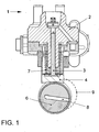
Weitere Vorteile und vorteilhafte Ausführungsformen und Weiterbildungen der Erfindung werden anhand der nachfolgenden Beschreibung unter Bezugnahme auf die Figur dargestellt. Sie zeigt eine schematische Darstellung einer Ausführungsform der erfindungsgemäßen Vorrichtung.Further advantages and advantageous embodiments and developments of the invention will be described with reference to the following description with reference to the figure. It shows a schematic representation of an embodiment of the device according to the invention.
In der einzigen Figur ist die erfindungsgemäße Vorrichtung schematisch dargestellt. Die Vorrichtung ist für den Einsatz in einem Kraftstoffeinspritzsystem für Verbrennungsmotoren bestimmt und weist eine Kolbenpumpe auf. Die Kolbenpumpe
Nach einer 180 Grad Drehung ist der Förderhub des Kolbens
BezugszeichenlisteLIST OF REFERENCE NUMBERS
- 11
- Kolbenpumpepiston pump
- 22
- Gehäuseblockhousing block
- 33
- Kolbenpiston
- 44
- Stößeltappet
- 55
- Exzenterelementeccentric
- 6 6
- Antriebswelledrive shaft
- 77
- Druckfedercompression spring
- 88th
- Zuführkanalfeed
- 99
- Stellung des Exzenterelementes bei DrehungPosition of the eccentric element during rotation
ZITATE ENTHALTEN IN DER BESCHREIBUNG QUOTES INCLUDE IN THE DESCRIPTION
Diese Liste der vom Anmelder aufgeführten Dokumente wurde automatisiert erzeugt und ist ausschließlich zur besseren Information des Lesers aufgenommen. Die Liste ist nicht Bestandteil der deutschen Patent- bzw. Gebrauchsmusteranmeldung. Das DPMA übernimmt keinerlei Haftung für etwaige Fehler oder Auslassungen.This list of the documents listed by the applicant has been generated automatically and is included solely for the better information of the reader. The list is not part of the German patent or utility model application. The DPMA assumes no liability for any errors or omissions.
Zitierte PatentliteraturCited patent literature
- WO 2004/072477 [0002] WO 2004/072477 [0002]
- DE 19705205 [0003] DE 19705205 [0003]
Claims (10)
Priority Applications (1)
| Application Number | Priority Date | Filing Date | Title |
|---|---|---|---|
| DE201210024924 DE102012024924A1 (en) | 2012-12-19 | 2012-12-19 | Device for driving piston pump, such as high-pressure pumps for common rail system, of motor vehicle, has piston pump unit which has working area limiting piston, where crank drive is formed for driving piston |
Applications Claiming Priority (1)
| Application Number | Priority Date | Filing Date | Title |
|---|---|---|---|
| DE201210024924 DE102012024924A1 (en) | 2012-12-19 | 2012-12-19 | Device for driving piston pump, such as high-pressure pumps for common rail system, of motor vehicle, has piston pump unit which has working area limiting piston, where crank drive is formed for driving piston |
Publications (1)
| Publication Number | Publication Date |
|---|---|
| DE102012024924A1 true DE102012024924A1 (en) | 2014-06-26 |
Family
ID=50878252
Family Applications (1)
| Application Number | Title | Priority Date | Filing Date |
|---|---|---|---|
| DE201210024924 Withdrawn DE102012024924A1 (en) | 2012-12-19 | 2012-12-19 | Device for driving piston pump, such as high-pressure pumps for common rail system, of motor vehicle, has piston pump unit which has working area limiting piston, where crank drive is formed for driving piston |
Country Status (1)
| Country | Link |
|---|---|
| DE (1) | DE102012024924A1 (en) |
Cited By (1)
| Publication number | Priority date | Publication date | Assignee | Title |
|---|---|---|---|---|
| WO2019201640A1 (en) * | 2018-04-19 | 2019-10-24 | Robert Bosch Gmbh | Plunger pump and contact mating structure used in the same |
Citations (6)
| Publication number | Priority date | Publication date | Assignee | Title |
|---|---|---|---|---|
| DE19705205A1 (en) | 1997-02-12 | 1998-08-13 | Bosch Gmbh Robert | Piston pump, esp. high pressure fuel injection pump for IC engine |
| EP0881380A1 (en) * | 1997-05-30 | 1998-12-02 | SIG Schweizerische Industrie-Gesellschaft | High-pressure feed pump |
| DE19920168A1 (en) * | 1998-05-16 | 1999-11-18 | Luk Automobiltech Gmbh & Co Kg | Radial piston pump of camshaft and cylinders for vehicle media |
| US6205980B1 (en) * | 1999-05-31 | 2001-03-27 | Sig Schweizerische Industrie-Gesellschaft | High-pressure delivery pump |
| DE10208574A1 (en) * | 2001-12-01 | 2003-06-12 | Bosch Gmbh Robert | Radial piston pump |
| WO2004072477A1 (en) | 2003-02-11 | 2004-08-26 | Ganser-Hydromag Ag | High pressure pump |
-
2012
- 2012-12-19 DE DE201210024924 patent/DE102012024924A1/en not_active Withdrawn
Patent Citations (6)
| Publication number | Priority date | Publication date | Assignee | Title |
|---|---|---|---|---|
| DE19705205A1 (en) | 1997-02-12 | 1998-08-13 | Bosch Gmbh Robert | Piston pump, esp. high pressure fuel injection pump for IC engine |
| EP0881380A1 (en) * | 1997-05-30 | 1998-12-02 | SIG Schweizerische Industrie-Gesellschaft | High-pressure feed pump |
| DE19920168A1 (en) * | 1998-05-16 | 1999-11-18 | Luk Automobiltech Gmbh & Co Kg | Radial piston pump of camshaft and cylinders for vehicle media |
| US6205980B1 (en) * | 1999-05-31 | 2001-03-27 | Sig Schweizerische Industrie-Gesellschaft | High-pressure delivery pump |
| DE10208574A1 (en) * | 2001-12-01 | 2003-06-12 | Bosch Gmbh Robert | Radial piston pump |
| WO2004072477A1 (en) | 2003-02-11 | 2004-08-26 | Ganser-Hydromag Ag | High pressure pump |
Cited By (1)
| Publication number | Priority date | Publication date | Assignee | Title |
|---|---|---|---|---|
| WO2019201640A1 (en) * | 2018-04-19 | 2019-10-24 | Robert Bosch Gmbh | Plunger pump and contact mating structure used in the same |
Similar Documents
| Publication | Publication Date | Title |
|---|---|---|
| EP2167818B1 (en) | High-pressure fuel pump with roller tappet | |
| DE102012204264A1 (en) | high pressure pump | |
| DE102015210815A1 (en) | Roller tappet for a piston pump, piston pump | |
| DE102012202720A1 (en) | high pressure pump | |
| EP2652309B1 (en) | High pressure pump | |
| WO2005111405A1 (en) | High-pressure pump for a fuel injection device pertaining to an internal combustion engine | |
| DE19858483A1 (en) | Hydraulic displacement machine, in particular displacement pump | |
| DE102011089399A1 (en) | Pump, in particular high-pressure fuel pump for a fuel injection device | |
| DE102008001960A1 (en) | Pump i.e. fuel high-pressure pump, for fuel injecting device of internal-combustion engine, has pump housing with main housing and flange made of aluminum, that is converted into layer of alumina ceramic in area of surface at bearing areas | |
| WO2008055745A1 (en) | Camshaft drive with geometric cam roller stabilization | |
| DE837206C (en) | Pistons for fluid operated piston engines | |
| DE102012024924A1 (en) | Device for driving piston pump, such as high-pressure pumps for common rail system, of motor vehicle, has piston pump unit which has working area limiting piston, where crank drive is formed for driving piston | |
| EP1211419A2 (en) | Device for pumping fluids, especially fuel | |
| DE102012212154A1 (en) | High pressure pump for conveying fluid e.g. diesel, in common-rail-injection system of diesel engine of motor vehicle, has shaft comprising recess such that channel discharging fluid from lubricating area is formed between shaft and bearing | |
| DE60203777T2 (en) | Fuel injection pump | |
| DE102013205466A1 (en) | axial piston | |
| DE102008042877A1 (en) | High-pressure pump arrangement for common rail injection system of internal-combustion engine of motor vehicle, has piston transmitting compression force for holding cam in attachment with control curve | |
| DE102010042025A1 (en) | Bearing element with rotatably mounted therein roller, in particular in the drive of a pump piston of a high-pressure fuel pump | |
| EP2872771B1 (en) | High-pressure pump | |
| DE102011082642A1 (en) | Pump, in particular high-pressure fuel pump for a fuel injection device of an internal combustion engine | |
| WO2010028882A1 (en) | Piston pump with surface pressure between a roller shoe and a roller mounted therein | |
| WO2009098095A1 (en) | Cam free of transverse force for common-rail high-pressure pumps | |
| DE102015210721A1 (en) | Roller tappet for a piston pump, piston pump | |
| DE102014207176A1 (en) | roller plunger | |
| DE102015120039A1 (en) | High pressure pump, in particular for fuel injection |
Legal Events
| Date | Code | Title | Description |
|---|---|---|---|
| R163 | Identified publications notified | ||
| R082 | Change of representative | ||
| R005 | Application deemed withdrawn due to failure to request examination |