DE102012007016B3 - Optical gas sensor - Google Patents
Optical gas sensor Download PDFInfo
- Publication number
- DE102012007016B3 DE102012007016B3 DE102012007016A DE102012007016A DE102012007016B3 DE 102012007016 B3 DE102012007016 B3 DE 102012007016B3 DE 102012007016 A DE102012007016 A DE 102012007016A DE 102012007016 A DE102012007016 A DE 102012007016A DE 102012007016 B3 DE102012007016 B3 DE 102012007016B3
- Authority
- DE
- Germany
- Prior art keywords
- temperature
- photosensor
- emitting diode
- led
- forward voltage
- Prior art date
- Legal status (The legal status is an assumption and is not a legal conclusion. Google has not performed a legal analysis and makes no representation as to the accuracy of the status listed.)
- Expired - Fee Related
Links
- 230000003287 optical effect Effects 0.000 title claims abstract description 16
- 238000005259 measurement Methods 0.000 claims abstract description 32
- 238000011156 evaluation Methods 0.000 claims abstract description 19
- 238000012937 correction Methods 0.000 claims abstract description 14
- 230000005855 radiation Effects 0.000 claims description 10
- 238000009529 body temperature measurement Methods 0.000 claims description 8
- 230000001105 regulatory effect Effects 0.000 claims description 3
- 238000010521 absorption reaction Methods 0.000 description 6
- 230000007423 decrease Effects 0.000 description 5
- 230000001419 dependent effect Effects 0.000 description 4
- 230000003595 spectral effect Effects 0.000 description 4
- 238000000295 emission spectrum Methods 0.000 description 3
- 230000035945 sensitivity Effects 0.000 description 3
- 238000010586 diagram Methods 0.000 description 2
- 238000005265 energy consumption Methods 0.000 description 2
- 238000002835 absorbance Methods 0.000 description 1
- 230000001788 irregular Effects 0.000 description 1
- 239000012528 membrane Substances 0.000 description 1
- 238000000034 method Methods 0.000 description 1
- 238000001228 spectrum Methods 0.000 description 1
- 230000006641 stabilisation Effects 0.000 description 1
- 238000011105 stabilization Methods 0.000 description 1
- 230000001629 suppression Effects 0.000 description 1
Images


Classifications
-
- G—PHYSICS
- G01—MEASURING; TESTING
- G01N—INVESTIGATING OR ANALYSING MATERIALS BY DETERMINING THEIR CHEMICAL OR PHYSICAL PROPERTIES
- G01N21/00—Investigating or analysing materials by the use of optical means, i.e. using sub-millimetre waves, infrared, visible or ultraviolet light
- G01N21/17—Systems in which incident light is modified in accordance with the properties of the material investigated
- G01N21/25—Colour; Spectral properties, i.e. comparison of effect of material on the light at two or more different wavelengths or wavelength bands
- G01N21/31—Investigating relative effect of material at wavelengths characteristic of specific elements or molecules, e.g. atomic absorption spectrometry
- G01N21/35—Investigating relative effect of material at wavelengths characteristic of specific elements or molecules, e.g. atomic absorption spectrometry using infrared light
- G01N21/3504—Investigating relative effect of material at wavelengths characteristic of specific elements or molecules, e.g. atomic absorption spectrometry using infrared light for analysing gases, e.g. multi-gas analysis
-
- G—PHYSICS
- G01—MEASURING; TESTING
- G01N—INVESTIGATING OR ANALYSING MATERIALS BY DETERMINING THEIR CHEMICAL OR PHYSICAL PROPERTIES
- G01N21/00—Investigating or analysing materials by the use of optical means, i.e. using sub-millimetre waves, infrared, visible or ultraviolet light
- G01N21/17—Systems in which incident light is modified in accordance with the properties of the material investigated
- G01N21/25—Colour; Spectral properties, i.e. comparison of effect of material on the light at two or more different wavelengths or wavelength bands
- G01N21/27—Colour; Spectral properties, i.e. comparison of effect of material on the light at two or more different wavelengths or wavelength bands using photo-electric detection ; circuits for computing concentration
- G01N21/274—Calibration, base line adjustment, drift correction
-
- G—PHYSICS
- G01—MEASURING; TESTING
- G01N—INVESTIGATING OR ANALYSING MATERIALS BY DETERMINING THEIR CHEMICAL OR PHYSICAL PROPERTIES
- G01N33/00—Investigating or analysing materials by specific methods not covered by groups G01N1/00 - G01N31/00
- G01N33/0004—Gaseous mixtures, e.g. polluted air
Abstract
Die Erfindung betrifft einen optischen Gassensor mit einer Leuchtdiode (2), einem Photosensor (8), einer Messstrecke zwischen Leuchtdiode und Photosensor, und einer Steuer- und Auswerteeinheit (16), die dazu eingerichtet ist, aus der Lichtintensitätsmessung durch den Photosensor die Konzentration eines Gases in der Messstrecke zu bestimmen. Erfindungsgemäß ist vorgesehen, dass die Steuer- und Auswerteeinheit (16) weiter dazu eingerichtet ist, die Vorwärtsspannung über die Leuchtdiode bei einem bekannten Strom zu messen, aus der erfassten Vorwärtsspannung über die Leuchtdiode mithilfe einer vorgegebenen Abhängigkeit der Vorwärtsspannung von der Temperatur die Temperatur der Leuchtdiode zu bestimmen, und eine Korrekturfunktion in Abhängigkeit von der bestimmten Leuchtdiodentemperatur anzuwenden, mit der die Messung auf eine vorgegebene Temperatur der Leuchtdiode umgerechnet wird.The invention relates to an optical gas sensor with a light-emitting diode (2), a photosensor (8), a measuring path between light-emitting diode and photosensor, and a control and evaluation unit (16), which is adapted from the light intensity measurement by the photosensor, the concentration of a Determine gas in the measuring section. According to the invention, the control and evaluation unit (16) is further configured to measure the forward voltage across the light emitting diode at a known current, from the detected forward voltage across the light emitting diode using a predetermined dependence of the forward voltage of the temperature, the temperature of the light emitting diode and to apply a correction function as a function of the determined LED temperature with which the measurement is converted to a predetermined temperature of the LED.
Description
Die vorliegende Erfindung betrifft einen optischen Gassensor mit einer Leuchtdiode, einem Photosensor, einer Messstrecke zwischen Leuchtdiode und Photosensor und einer Steuer- und Auswerteeinheit, die dazu eingerichtet ist, auf Grundlage der Messung des Photosensors die Konzentration eines Gases in der Messstrecke zu bestimmen, wobei die Steuer- und Auswerteeinheit weiter dazu eingerichtet ist, die Vorwärtsspannung über die Leuchtdiode bei einem bekannten Strom zu messen, aus der erfassten Vorwärtsspannung über die Leuchtdiode mithilfe einer vorgegebenen Abhängigkeit der Vorwärtsspannung von der Temperatur die Temperatur der Leuchtdiode zu bestimmen, und eine Korrekturfunktion in Abhängigkeit von der bestimmten Leuchtdiodentemperatur anzuwenden, mit der die Messung auf eine vorgegebene Temperatur der Leuchtdiode umgerechnet wird.The present invention relates to an optical gas sensor with a light-emitting diode, a photosensor, a measuring path between light emitting diode and photosensor and a control and evaluation unit which is adapted to determine based on the measurement of the photosensor, the concentration of a gas in the measuring section, wherein the Control and evaluation unit is further configured to measure the forward voltage across the LED at a known current, from the detected forward voltage across the LED using a predetermined dependence of the forward voltage of the temperature to determine the temperature of the LED, and a correction function as a function of the specific LED temperature, with which the measurement is converted to a predetermined temperature of the LED.
Optische Gassensoren arbeiten mit einer Lichtquelle, einem Photosensor und einer zwischen der Lichtquelle und dem Photosensor liegenden Messstrecke. Mit einem Bandpassfilter kann ein Wellenlängenbereich ausgewählt werden, in dem das Zielgas eine charakteristische Absorption hat. Als Lichtquellen dienen thermische Lichtquellen, wie Membranstrahler oder Glühwendeln, Laser oder Leuchtdioden (insbesondere im IR und UV-Bereich). Thermische Lichtquellen emittieren spektral sehr breitbandig. Damit fließt aber viel Energie in spektrale Bereiche, die nicht zur Auswertung und Berechnung von Gaskonzentrationen herangezogen werden. Derartige Gassensoren sind daher in Bezug auf ihren Energieverbrauch wenig effizient. Außerdem sind sie ohne mechanische Zusatzkomponenten nicht schnell in ihrer Leistung modulierbar, was die Nutzung von Rauschunterdrückungsverfahren bei gleichzeitiger schneller Ansprechzeit einschränkt.Optical gas sensors operate with a light source, a photosensor, and a measurement path between the light source and the photosensor. With a bandpass filter, a wavelength range can be selected in which the target gas has a characteristic absorption. The light sources used are thermal light sources, such as membrane radiators or incandescent filaments, lasers or light-emitting diodes (in particular in the IR and UV range). Thermal light sources emit spectrally very broadband. However, a lot of energy flows into spectral areas, which are not used for the evaluation and calculation of gas concentrations. Such gas sensors are therefore inefficient in terms of their energy consumption. In addition, they can not be quickly modulated in performance without additional mechanical components, which limits the use of noise suppression techniques while providing fast response time.
Laser liefern hingegen meist ein sehr gutes Signal/Rausch-Verhältnis, sind aber relativ teuer und müssen thermisch stabilisiert werden.In contrast, lasers usually provide a very good signal-to-noise ratio, but are relatively expensive and must be thermally stabilized.
Leuchtdioden (LEDs) sind wesentlich kostengünstiger als Laser und emittieren in einem spektral eingeschränkten Bereich, so dass sie im Vergleich zu thermischen Lichtquellen in Bezug auf ihren Energieverbrauch effizienter sind. LEDs sind außerdem wie auch Laser schnell elektrisch modulierbar. Andererseits zeigt die spektrale Emissionscharakteristik von LEDs eine thermische Drift, die sich in thermisch nicht stabilisierten optischen Gassensoren störend bemerkbar macht.Light-emitting diodes (LEDs) are much less expensive than lasers and emit in a spectrally restricted area, making them more efficient in terms of energy consumption compared to thermal light sources. LEDs are also fast electrically modulable as well as lasers. On the other hand, the spectral emission characteristic of LEDs shows a thermal drift, which is disturbing in thermally unstabilized optical gas sensors.
Ein optischer Gassensor mit den Merkmalen des Oberbegriffs von Anspruch 1 ist aus
Es ist Aufgabe der vorliegenden Erfindung, einen optischen Gassensor anzugeben, der mit einer LED als Lichtquelle auch ohne thermische Stabilisierung genaue Messungen erlaubt und es erlaubt, die temperaturabhängige Messunsicherheit einzubeziehen.It is an object of the present invention to provide an optical gas sensor that allows accurate measurements with an LED as a light source even without thermal stabilization and allows to include the temperature-dependent measurement uncertainty.
Zur Lösung dieser Aufgabe dienen die kennzeichnenden Merkmale des Patentanspruchs 1 in Verbindung mit dessen Oberbegriff. Vorteilhafte Ausführungsformen sind in den Unteransprüchen angegeben.To solve this problem are the characterizing features of claim 1 in conjunction with the preamble. Advantageous embodiments are specified in the subclaims.
Erfindungsgemäß ist die Steuer- und Auswerteeinheit weiter dazu eingerichtet ist, die mit steigender Temperatur der Leuchtdiode wachsende Messunsicherheit zu reduzieren, indem die Strahlungsleistung der Leuchtdiode auf eine vorgegebene, konstante Strahlungsleistung geregelt wird, wodurch die Messunsicherheit mit steigender Temperatur der Leuchtdiode nicht mehr ansteigt, oder die Messunsicherheit der bestimmten Gaskonzentration zu bestimmen und neben der Gaskonzentration anzuzeigen.According to the invention, the control and evaluation unit is further configured to reduce the increasing uncertainty with increasing temperature of the light emitting diode by the radiation power of the light emitting diode is regulated to a predetermined, constant radiation power, whereby the measurement uncertainty no longer increases with increasing temperature of the light emitting diode, or to determine the measurement uncertainty of the specific gas concentration and to display it next to the gas concentration.
In einer bevorzugten Ausführungsform ist die Steuer- und Auswerteeinheit weiter dazu eingerichtet, den Photosensor abwechselnd in einem Modus zur Lichtintensitätsmessung und einem Temperaturmessmodus zu betreiben, in dem ein vorgegebener konstanter Strom über den Photosensor angelegt und die resultierende Vorwärtsspannung über den Photosensor erfasst wird. Auf Grundlage einer vorbestimmten Abhängigkeit der Vorwärtsspannung von der Temperatur des Photosensors wird in der Steuer- und Auswerteeinheit eine vorab bestimmte Korrekturfunktion in Abhängigkeit von der Photosensortemperatur auf die Messung des Photosensors angewendet und die Messung auf eine vorgegebene Temperatur des Photosensors umgerechnet.In a preferred embodiment, the control and evaluation unit is further configured to operate the photosensor alternately in a mode for light intensity measurement and a temperature measurement mode in which a predetermined constant current is applied across the photosensor and the resulting forward voltage is detected via the photosensor. Based on a predetermined dependence of the forward voltage on the temperature of the photosensor, a predetermined correction function in dependence on the photosensor temperature is applied to the measurement of the photosensor in the control and evaluation unit and the measurement is converted to a predetermined temperature of the photosensor.
Die Erfindung wird im Folgenden anhand von Beispielen im Zusammenhang mit den Zeichnungen beschrieben, in denen: The invention will now be described by way of example in conjunction with the drawings, in which:
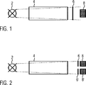
In
Die
Durch Messung der Vorwärtsspannung über die Leuchtdiode bei festem Strom kann durch die in
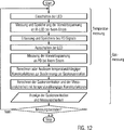
In
Die dazu benötigten Schaltungen sind in
Anschließend werden Korrekturfaktoren aus einer gespeicherten Tabelle aufgerufen oder nach vorgegebenen Abhängigkeiten ermittelt, mit denen eine darauffolgende Messung der Gaskonzentration auf vorgegebene Temperaturen von Leuchtdiode und Photodiode umgerechnet wird.Subsequently, correction factors are retrieved from a stored table or determined according to predetermined dependencies with which a subsequent measurement of the gas concentration is converted to predetermined temperatures of the light-emitting diode and photodiode.
Darauf folgt die Messung der Gaskonzentration, wozu die Leuchtdiode eingeschaltet wird und das resultierende Photodiodensignal erfasst wird. Aus dem Photodiodensignal wird die Gaskonzentration mit temperaturabhängigen Korrekturen für die Leuchtdiodentemperatur und die Photodiodentemperatur berechnet. Anschließend wird die Leuchtdiode wieder ausgeschaltet und die bestimmte Gaskonzentration angezeigt. Daraufhin wird geprüft, wie lange die letzte Temperaturmessung zurückliegt. Die Temperaturmessung kann in regelmäßigen oder unregelmäßigen Abständen wiederholt werden, zum Beispiel alle 5 Minuten. Liegt die letzte Temperaturmessung länger als vorgesehen zurück, kehrt die Steuer- und Auswerteeinheit wieder zum Ausgangspunkt zurück und führt eine erneute Temperaturmessung durch. Anderenfalls schließt sich direkt eine weitere Messung der Gaskonzentration an.This is followed by the measurement of the gas concentration, for which purpose the light-emitting diode is switched on and the resulting photodiode signal is detected. From the photodiode signal, the gas concentration is calculated with temperature-dependent corrections for the LED temperature and the photodiode temperature. Then the LED is switched off again and the specific gas concentration is displayed. It then checks how long ago the last temperature measurement took place. The temperature measurement can be repeated at regular or irregular intervals, for example every 5 minutes. If the last temperature measurement is longer than intended, the control and evaluation unit returns to the starting point and carries out another temperature measurement. Otherwise, a further measurement of the gas concentration follows directly.
Neben der Anzeige der so bestimmten Gaskonzentration kann auch eine Messunsicherheit mit temperaturabhängigen Korrekturfaktoren bestimmt und angezeigt werden. Dafür wird die vorbekannte Messunsicherheit der Gaskonzentration bei der Referenztemperatur mit zwei Korrekturfaktoren multipliziert. Der eine Korrekturfaktor ist der Quotient aus emittierter Strahlungsleistung der LED im Wellenlängenbereich der Gasabsorption bei Referenztemperatur durch emittierte Strahlungsleistung der LED im Wellenlängenbereich der Gasabsorption bei gemessener Temperatur. Der andere Korrekturfaktor ist der Quotient aus Detektivität des Detektors im Wellenlängenbereich der Gasabsorption bei Referenztemperatur durch Detektivität des Detektors im Bereich der Gasabsorption bei gemessener Temperatur. Es kann auch experimentell die Messunsicherheit des Gerätes bei verschiedenen Temperaturen gemessen und in einer Look-up Tabelle hinterlegt werden.In addition to the display of the gas concentration determined in this way, a measurement uncertainty with temperature-dependent correction factors can also be determined and displayed. For this purpose, the previously known measurement uncertainty of the gas concentration at the reference temperature is multiplied by two correction factors. The one correction factor is the quotient of emitted radiation power of the LED in the wavelength range of the gas absorption at reference temperature by emitted radiation power of the LED in the wavelength range of the gas absorption at measured temperature. The other correction factor is the quotient of detectivity of the detector in the wavelength range of gas absorption at reference temperature by detectivity of the detector in the range of gas absorption at measured temperature. It is also possible experimentally to measure the measurement uncertainty of the device at different temperatures and store it in a look-up table.
Die Messunsicherheit nimmt aufgrund der o. g. Ausführungen mit steigender Temperatur deutlich zu. In der erfindungsgemäßen Ausführung kann die Zunahme der Messunsicherheit mit steigender Temperatur reduziert werden. Hierzu kann die Strahlungsleistung der LED, die mit zunehmender Temperatur abnimmt (
Eine weitere vorteilhafte Ausführungsform besteht darin, die Abnahme der Detektivität des Photosensors mit steigender Temperatur durch eine Übererhöhung der Strahlungsleistung der LED zu kompensieren. Hierbei wird mit steigender Temperatur nicht nur die Strahlungsleistung der LED konstant gehalten, sondern noch weiter erhöht. Dies geschieht ebenfalls über eine Erhöhung des LED Stromes. Die notwendige Stromhöhe kann ebenfalls über eine Look-up Tabelle bzw. eine Funktionsgleichung ermittelt und über die Steuer- und Auswerteeinheit nachgeführt werden.A further advantageous embodiment is to compensate for the decrease in the detectivity of the photosensor with increasing temperature by an increase in the radiant power of the LED. Here, with increasing temperature, not only the radiation power of the LED is kept constant, but increased even further. This is also done by increasing the LED current. The necessary current level can also be determined via a look-up table or a function equation and tracked via the control and evaluation unit.
BezugszeichenlisteLIST OF REFERENCE NUMBERS
- 22
- Leuchtdiodeled
- 44
- Gasküvettegas cell
- 66
- BandpassfilterBandpass filter
- 88th
- Photodiodephotodiode
- 1010
- Stromquellepower source
- 1212
- Operationsverstärkeroperational amplifiers
- 1414
- Analog/Digital-WandlerAnalog / digital converter
- 1616
- Steuer- und AuswerteeinheitControl and evaluation unit
Claims (4)
Priority Applications (3)
| Application Number | Priority Date | Filing Date | Title |
|---|---|---|---|
| DE102012007016A DE102012007016B3 (en) | 2012-04-05 | 2012-04-05 | Optical gas sensor |
| US13/736,226 US8649012B2 (en) | 2012-04-05 | 2013-01-08 | Optical gas sensor |
| GB1304519.0A GB2500993B (en) | 2012-04-05 | 2013-03-13 | Optical gas sensor |
Applications Claiming Priority (1)
| Application Number | Priority Date | Filing Date | Title |
|---|---|---|---|
| DE102012007016A DE102012007016B3 (en) | 2012-04-05 | 2012-04-05 | Optical gas sensor |
Publications (1)
| Publication Number | Publication Date |
|---|---|
| DE102012007016B3 true DE102012007016B3 (en) | 2013-10-10 |
Family
ID=48189842
Family Applications (1)
| Application Number | Title | Priority Date | Filing Date |
|---|---|---|---|
| DE102012007016A Expired - Fee Related DE102012007016B3 (en) | 2012-04-05 | 2012-04-05 | Optical gas sensor |
Country Status (3)
| Country | Link |
|---|---|
| US (1) | US8649012B2 (en) |
| DE (1) | DE102012007016B3 (en) |
| GB (1) | GB2500993B (en) |
Cited By (1)
| Publication number | Priority date | Publication date | Assignee | Title |
|---|---|---|---|---|
| EP3581898A1 (en) | 2018-06-13 | 2019-12-18 | E+E Elektronik Ges.M.B.H. | Electronic assembly, optical gas sensor comprising such an electronic assembly and method for combined photocurrent and temperature measuring using such an electronic assembly |
Families Citing this family (10)
| Publication number | Priority date | Publication date | Assignee | Title |
|---|---|---|---|---|
| GB201018418D0 (en) * | 2010-11-01 | 2010-12-15 | Gas Sensing Solutions Ltd | Temperature calibration methods and apparatus for optical absorption gas sensors, and optical absorption gas sensors thereby calibrated |
| FR2977315B1 (en) * | 2011-06-29 | 2013-06-28 | Schneider Electric Ind Sas | DETECTION SYSTEM WITH LOW ENERGY CONSUMPTION |
| CN103528959A (en) * | 2013-10-24 | 2014-01-22 | 重庆川仪自动化股份有限公司 | Gas concentration measurement method and device |
| US20150268158A1 (en) * | 2014-03-21 | 2015-09-24 | Battelle Memorial Institute | Gas Sensor and Method for Sensing Presence of Ethanol Vapor in a Cabin |
| JP6622049B2 (en) * | 2015-06-30 | 2019-12-18 | 旭化成エレクトロニクス株式会社 | Gas concentration measuring device |
| US20170191877A1 (en) * | 2015-12-31 | 2017-07-06 | Google Inc. | Systems and methods for using a power characteristic of an optoelectronic component of a hazard detection system to determine a smoke condition of an environment |
| US20170191876A1 (en) * | 2015-12-31 | 2017-07-06 | Google Inc. | Systems and methods for using a power characteristic of an optoelectronic component of a hazard detection system to determine a temperature of an environment |
| DE102016003283B4 (en) * | 2016-03-18 | 2022-05-19 | Dräger Safety AG & Co. KGaA | Gas measuring device with a test device for checking a gas sensor |
| DE102016003284B4 (en) * | 2016-03-18 | 2022-05-19 | Dräger Safety AG & Co. KGaA | Gas measuring device with a test device for checking a gas sensor |
| JP7228209B2 (en) * | 2020-03-13 | 2023-02-24 | 国立大学法人徳島大学 | Concentration measurement method |
Citations (4)
| Publication number | Priority date | Publication date | Assignee | Title |
|---|---|---|---|---|
| US6850013B1 (en) * | 1998-07-04 | 2005-02-01 | Qinetiq Limited | Infrared light emitting diodes |
| WO2009019467A1 (en) * | 2007-08-06 | 2009-02-12 | Gas Sensing Solutions Limited | Temperature compensation for gas detection |
| US20090235720A1 (en) * | 2006-02-06 | 2009-09-24 | Gas Sensing Solutions Limited | Dome Gas Sensor |
| WO2012059744A1 (en) * | 2010-11-01 | 2012-05-10 | Gas Sensing Solutions Ltd. | Apparatus and method for generating light pulses from leds in optical absorption gas sensors |
Family Cites Families (9)
| Publication number | Priority date | Publication date | Assignee | Title |
|---|---|---|---|---|
| US5022045A (en) * | 1985-08-06 | 1991-06-04 | Elliott Stanley B | Optical-type, phase transition humidity-responsive devices |
| US4913150A (en) | 1986-08-18 | 1990-04-03 | Physio-Control Corporation | Method and apparatus for the automatic calibration of signals employed in oximetry |
| US5532122A (en) * | 1993-10-12 | 1996-07-02 | Biotraces, Inc. | Quantitation of gamma and x-ray emitting isotopes |
| JP3032677B2 (en) * | 1994-03-24 | 2000-04-17 | アヴェンティス・リサーチ・ウント・テクノロジーズ・ゲーエムベーハー・ウント・コー・カーゲー | Fuel vapor discrimination method and apparatus |
| US7179653B2 (en) * | 2000-03-31 | 2007-02-20 | Showa Denko K.K. | Measuring method for concentration of halogen and fluorine compound, measuring equipment thereof and manufacturing method of halogen compound |
| US7110917B2 (en) * | 2003-11-14 | 2006-09-19 | Ricoh Company, Ltd. | Abnormality determining method, and abnormality determining apparatus and image forming apparatus using same |
| US8233150B2 (en) * | 2006-12-12 | 2012-07-31 | Koninklijke Philips Electronics N.V. | Sample concentration detector with temperature compensation |
| DE102009011421B3 (en) * | 2009-03-03 | 2010-04-15 | Drägerwerk AG & Co. KGaA | Method for operating gas concentration measuring device for e.g. monitoring concentration of alcohol in breathing gas of animal, involves synchronizing control voltage with light control signals |
| GB201018418D0 (en) | 2010-11-01 | 2010-12-15 | Gas Sensing Solutions Ltd | Temperature calibration methods and apparatus for optical absorption gas sensors, and optical absorption gas sensors thereby calibrated |
-
2012
- 2012-04-05 DE DE102012007016A patent/DE102012007016B3/en not_active Expired - Fee Related
-
2013
- 2013-01-08 US US13/736,226 patent/US8649012B2/en active Active
- 2013-03-13 GB GB1304519.0A patent/GB2500993B/en not_active Expired - Fee Related
Patent Citations (4)
| Publication number | Priority date | Publication date | Assignee | Title |
|---|---|---|---|---|
| US6850013B1 (en) * | 1998-07-04 | 2005-02-01 | Qinetiq Limited | Infrared light emitting diodes |
| US20090235720A1 (en) * | 2006-02-06 | 2009-09-24 | Gas Sensing Solutions Limited | Dome Gas Sensor |
| WO2009019467A1 (en) * | 2007-08-06 | 2009-02-12 | Gas Sensing Solutions Limited | Temperature compensation for gas detection |
| WO2012059744A1 (en) * | 2010-11-01 | 2012-05-10 | Gas Sensing Solutions Ltd. | Apparatus and method for generating light pulses from leds in optical absorption gas sensors |
Cited By (5)
| Publication number | Priority date | Publication date | Assignee | Title |
|---|---|---|---|---|
| EP3581898A1 (en) | 2018-06-13 | 2019-12-18 | E+E Elektronik Ges.M.B.H. | Electronic assembly, optical gas sensor comprising such an electronic assembly and method for combined photocurrent and temperature measuring using such an electronic assembly |
| DE102019208173A1 (en) | 2018-06-13 | 2019-12-19 | E+E Elektronik Ges.M.B.H. | Electronic arrangement, optical gas sensor comprising such an electronic arrangement and method for combined photocurrent and temperature measurement by means of such an electronic arrangement |
| JP2019215316A (en) * | 2018-06-13 | 2019-12-19 | エー・ウント・エー・エレクトロニック・ゲゼルシヤフト・ミト・ベシユレンクテル・ハフツング | Electronic device, optical gas sensor with electronic device, and method for measuring photocurrent and temperature in combination using electronic device |
| US11262295B2 (en) | 2018-06-13 | 2022-03-01 | E+E Elektronik Ges.M.B.H. | Electronic arrangement, optical gas sensor including such an electronic arrangement, and method for combined photocurrent and temperature measurement using such an electronic arrangement |
| JP7266436B2 (en) | 2018-06-13 | 2023-04-28 | エー・ウント・エー・エレクトロニック・ゲゼルシヤフト・ミト・ベシユレンクテル・ハフツング | Optical gas sensor with electronics and method for combined measurement of photocurrent and temperature using such electronics |
Also Published As
| Publication number | Publication date |
|---|---|
| US20130265579A1 (en) | 2013-10-10 |
| GB2500993B (en) | 2015-07-08 |
| GB201304519D0 (en) | 2013-04-24 |
| GB2500993A (en) | 2013-10-09 |
| US8649012B2 (en) | 2014-02-11 |
Similar Documents
| Publication | Publication Date | Title |
|---|---|---|
| DE102012007016B3 (en) | Optical gas sensor | |
| JP5023507B2 (en) | Wavelength calibration method and wavelength calibration apparatus | |
| EP1754395B1 (en) | Method for stabilizing the temperature sensitivity of the emission of light of an led | |
| WO2000073768A2 (en) | Gas sensor configuration | |
| DE102013202289B4 (en) | Method and arrangement for driving a wavelength-tunable laser diode in a spectrometer | |
| DE102008054056A1 (en) | Spectrometric arrangement and method for determining a temperature value for a detector of a spectrometer | |
| DE102011080086B4 (en) | Method for measuring the concentration of a gas component in a sample gas | |
| DE102004025448B4 (en) | Method for measuring a spectrum of a sample by means of an infrared spectrometer and such an infrared spectrometer | |
| JP4223881B2 (en) | Concentration measurement system | |
| EP3839455A1 (en) | Device for high resolution detection of the concentration of substances in fluid media | |
| DE102006010100B4 (en) | Apparatus and method for spectroscopic measurement | |
| EP2010890A2 (en) | Method and system for the production of a test result indicative of the presence of a substance in a sample based on a spectrometric measurement | |
| DE102013213458A1 (en) | Method for measuring the concentration of a gas component in a sample gas | |
| DE102017130988B4 (en) | DEVICES AND METHODS FOR UTILIZING THE PHOTOACOUSTIC EFFECT | |
| EP2988950A1 (en) | Photoluminescence measuring apparatus and method for rapidly determining the absolute luminescence intensity | |
| EP3372988A1 (en) | Method and device for measuring the concentration of a substance in a gaseous medium by means of absorption spectroscopy | |
| DE102016015424B4 (en) | Device for determining a concentration of a gas | |
| DE10245822A1 (en) | Method and gas measuring cell for the detection of different gases | |
| EP1370832B1 (en) | Method and device for detecting dispersive effects on a measurement | |
| DE112020003132T5 (en) | multi-channel gas sensor | |
| DE102007005642A1 (en) | Device and method for the spectral diagnosis of substances and / or surfaces | |
| DE3307132A1 (en) | INFRARED GAS ANALYSIS METHOD AND GAS ANALYZER | |
| EP0886772B1 (en) | Analysis system | |
| EP3543682B1 (en) | Method of operating an optical measuring system for measuring the concentration of a gas component in a gas to be measured | |
| AT522840B1 (en) | Method for compensation in a measuring system |
Legal Events
| Date | Code | Title | Description |
|---|---|---|---|
| R012 | Request for examination validly filed | ||
| R016 | Response to examination communication | ||
| R018 | Grant decision by examination section/examining division | ||
| R020 | Patent grant now final | ||
| R079 | Amendment of ipc main class |
Free format text: PREVIOUS MAIN CLASS: G01N0021350000 Ipc: G01N0021350400 |
|
| R020 | Patent grant now final |
Effective date: 20140111 |
|
| R079 | Amendment of ipc main class |
Free format text: PREVIOUS MAIN CLASS: G01N0021350000 Ipc: G01N0021350400 Effective date: 20140226 |
|
| R119 | Application deemed withdrawn, or ip right lapsed, due to non-payment of renewal fee |