DE102011106986B3 - Orientation sensor for space probe for determination of orientation of sensor housing in gravitational field in aerospace industry, has evaluation unit i.e. microprocessor, determining position of ball in inner side of sensor housing - Google Patents
Orientation sensor for space probe for determination of orientation of sensor housing in gravitational field in aerospace industry, has evaluation unit i.e. microprocessor, determining position of ball in inner side of sensor housing Download PDFInfo
- Publication number
- DE102011106986B3 DE102011106986B3 DE201110106986 DE102011106986A DE102011106986B3 DE 102011106986 B3 DE102011106986 B3 DE 102011106986B3 DE 201110106986 DE201110106986 DE 201110106986 DE 102011106986 A DE102011106986 A DE 102011106986A DE 102011106986 B3 DE102011106986 B3 DE 102011106986B3
- Authority
- DE
- Germany
- Prior art keywords
- sensor
- contacts
- ball
- housing
- orientation
- Prior art date
- Legal status (The legal status is an assumption and is not a legal conclusion. Google has not performed a legal analysis and makes no representation as to the accuracy of the status listed.)
- Expired - Fee Related
Links
Images

Classifications
-
- G—PHYSICS
- G01—MEASURING; TESTING
- G01C—MEASURING DISTANCES, LEVELS OR BEARINGS; SURVEYING; NAVIGATION; GYROSCOPIC INSTRUMENTS; PHOTOGRAMMETRY OR VIDEOGRAMMETRY
- G01C9/00—Measuring inclination, e.g. by clinometers, by levels
- G01C9/10—Measuring inclination, e.g. by clinometers, by levels by using rolling bodies, e.g. spheres, cylinders, mercury droplets
Abstract
Description
Die Erfindung betrifft einen Sensor und ein Verfahren zur Ermittlung einer Orientierung eines Sensorgehäuses in einem auf den Sensor einwirkenden Schwerefeld. Weiterhin betrifft die Erfindung eine Raumsonde mit einem ebensolchen Sensor. Die Erfindung findet Anwendung in der Raumfahrtindustrie.The invention relates to a sensor and a method for determining an orientation of a sensor housing in a gravitational field acting on the sensor. Furthermore, the invention relates to a space probe with a similar sensor. The invention finds application in the space industry.
Zur Erkundung des Weltraumes wurden und werden zahlreiche Raumsonden gebaut, die unterschiedliche Aufgaben erfüllen. Es ist bekannt, dass bei (große) Raumsonden, die bspw. gezielt auf Planeten gelandet werden sollen, Vorrichtungen zur Ermittlung der Orientierung der Raumsonde im Schwerefeld des Planeten erforderlich sind, bspw. um eine Landung der Raumsonde auf dem Planeten in der richtigen Orientierung zu gewährleisten. Hierzu sind eine Vielzahl von technisch hochentwickelten aktiven Lagesensoren und Orientierungssensoren bekannt. Diese Sensoren sind aufgrund ihrer Komplexität sehr teuer, ausfallgefährdet und müssen gegen Strahlung geschützt werden. Weiterhin beanspruchen sie viel Platz in der Raumsonde und haben einen hohen Strombedarf.To explore space, numerous space probes have been and are being built to perform different tasks. It is known that in (large) space probes, which are to be targeted, for example, landed on planets, devices for determining the orientation of the spacecraft in the gravitational field of the planet are required, for example, a landing of the spacecraft on the planet in the correct orientation guarantee. For this purpose, a large number of technically advanced active position sensors and orientation sensors are known. Due to their complexity, these sensors are very expensive, prone to failure and must be protected against radiation. Furthermore, they require a lot of space in the spacecraft and have a high power requirement.
Aus der
Aus der
Aus der
Aus der
Aus der
Schließlich ist aus der
Für (kleine) Raumsonden, die auf kleinen Himmelskörpern, wie bspw. Kometen oder Asteroiden landen sollen, sind die bekannten Lage- und Orientierungssensoren nicht geeignet, da sie zu schwer und zu teuer sind, sowie einen zu großen Platzbedarf haben. Gleichwohl ist es für derartige kleine Raumsonden je nach Anwendung ebenfalls erforderlich die Orientierung der Raumsonde in Bezug auf den Himmelkörper zu kennen, um bspw. die von der Raumsonde erfassten Messergebnisse beurteilen zu können.For (small) space probes, which are to land on small celestial bodies, such as comets or asteroids, the known position and orientation sensors are not suitable because they are too heavy and too expensive, and have too large a space requirement. However, it is also necessary for such small space probes, depending on the application, to know the orientation of the space probe with respect to the heavenly body in order to be able to assess, for example, the measurement results recorded by the spacecraft.
Die hier vorgestellte Erfindung beschreibt eine Methode, wie ein passiver Lagesensor kompakt und strahlungsfest realisiert werden kann, so dass er für kleine kompakte Explorationssysteme verwendet werden kann.The invention presented here describes a method of how a passive position sensor can be realized in a compact and radiation-resistant manner, so that it can be used for small compact exploration systems.
Aufgabe der Erfindung ist es, einen Sensor und ein Verfahren anzugeben, die eine einfache, nicht störanfällige Ermittlung einer beliebigen dreidimensionalen Orientierung des Sensors in einem Schwerefeld ermöglichen. Der Sensor soll günstig herstellbar sein, eine geringe Masse, ein geringes Bauvolumen aufweisen, zuverlässig arbeiten, einen geringen Energiebedarf haben und insbesondere als Orientierungssensor für Raumsonden geeignet sein.The object of the invention is to provide a sensor and a method which allow a simple, not susceptible to interference determination of any three-dimensional orientation of the sensor in a gravitational field. The sensor should be inexpensive to manufacture, have a low mass, a low overall volume, work reliably, have low energy consumption and be suitable in particular as an orientation sensor for space probes.
Die Erfindung ergibt sich aus den Merkmalen der unabhängigen Ansprüche. Vorteilhafte Weiterbildungen und Ausgestaltungen sind Gegenstand der abhängigen Ansprüche. Weitere Merkmale, Anwendungsmöglichkeiten und Vorteile der Erfindung ergeben sich aus der nachfolgenden Beschreibung, sowie der Erläuterung von Ausführungsbeispielen der Erfindung, die in den Figuren dargestellt sind.The invention results from the features of the independent claims. Advantageous developments and refinements are the subject of the dependent claims. Other features, applications and advantages of the invention will become apparent from the following description, and the explanation of embodiments of the invention, which are illustrated in the figures.
Der vorrichtungsgemäße Aspekt der Aufgabe ist mit einem Sensor zur Ermittlung einer Orientierung eines Sensorgehäuses in einem auf den Sensor einwirkenden Schwerefeld gelöst. Unter dem Begriff „Schwerefeld” wird vorliegend das Feld der Schwerebeschleunigung, d. h. die am jeweiligen Ort des Sensors auf den Sensor einwirkende Beschleunigung als der Vektorsumme von Gravitationsbeschleunigung und Zentrifugalbeschleunigung, verstanden. Unter dem Begriff „Orientierung” wird vorliegend die Ausrichtung/die Drehung, insbesondere des Sensorgehäuses, gegenüber einem Bezugssystem bzw. einer ausgezeichneten Richtung (der Schwerkraft) verstanden. Unter dem Begriff ”Kugel” werden vorliegend neben dem gebräuchlichen Wortsinn „Kugel”: Rotationsfläche oder spezielle Fläche zweiter Ordnung, beschrieben als die Menge aller Punkte im dreidimensionalen euklidischen Raum, deren Abstand von einem festen Punkt des Raumes gleich einer gegebenen positiven reellen Zahl r ist, auch Polyeder, insbesondere catalanische Körper verstanden.The device-related aspect of the object is achieved with a sensor for determining an orientation of a sensor housing in a gravitational field acting on the sensor. The term "gravitational field" in the present case, the field of gravitational acceleration, d. H. understood the acceleration acting on the sensor at the respective location of the sensor as the vector sum of gravitational acceleration and centrifugal acceleration. The term "orientation" is understood here to mean the alignment / rotation, in particular of the sensor housing, with respect to a reference system or an excellent direction (of gravity). The term "sphere" is used here in addition to the usual meaning "sphere": surface of revolution or special surface second order, described as the set of all points in the three-dimensional Euclidean space whose distance from a fixed point of space equal to a given positive real number r , also polyhedra, especially Catalan body understood.
Der erfindungsgemäße Sensor umfasst zumindest das Sensorgehäuse mit einem Gehäuseinnenraum in Form einer Kugel, eine innerhalb des Gehäuseinnenraums bewegliche Kugel mit einer leitenden Oberfläche, eine Vielzahl von an/auf einer Innenseite des Sensorgehäuses voneinander beabstandet und verteilt angeordneten elektrischen Kontakten, die jeweils voneinander und vom Sensorgehäuse elektrisch isoliert sind, und eine mit den elektrischen Kontakten verbundene Auswerteeinheit, die derart ausgeführt und eingerichtet ist, dass die Orientierung des Sensorgehäuses im Schwerefeld durch eine Auswertung eines elektrischen Schaltzustandes der Kontakte ermittelbar ist. Der Schaltzustand der elektrischen Kontakte ist dadurch änderbar, dass die Kugel durch eine auf diese einwirkende Schwerkraft an eine von einer Richtung der Schwerkraft abhängige Position auf der Innenseite des Sensorgehäuses bewegt wird und dort zwischen mindestens zwei elektrischen Kontakten über die leitende Kugeloberfläche eine elektrisch leitende Verbindung herstellt. Durch diese leitende Verbindung zwischen den mindestens zwei Kontakten wird der Schaltzustand dieser mindestens zwei Kontakte geändert, d. h. sie sind dann leitend miteinander verbunden. Da die Positionen der einzelnen elektrischen Kontakte auf/an der Innenseite des Gehäuseinnenraums bekannt sind, kann aus der Ermittlung derjenigen Kontakte, deren Schaltzustand sich geändert hat, zunächst die Richtung der auf den Sensor wirkenden Schwerkraft und damit die Orientierung des Sensorgehäuses im Schwerefeld bestimmt werden.The sensor according to the invention comprises at least the sensor housing having a housing interior in the form of a sphere, a ball movable within the housing interior with a conductive surface, a multiplicity of electrical contacts spaced apart from one another and distributed on an inner side of the sensor housing, each being spaced from one another and from the sensor housing are electrically isolated, and an evaluation unit connected to the electrical contacts, which is designed and arranged such that the orientation of the sensor housing in the gravitational field can be determined by an evaluation of an electrical switching state of the contacts. The switching state of the electrical contacts is changeable in that the ball is moved by a force acting on this gravity to a dependent of a direction of gravity position on the inside of the sensor housing and there establishes an electrically conductive connection between at least two electrical contacts on the conductive ball surface , Through this conductive connection between the at least two contacts, the switching state of these at least two contacts is changed, d. H. they are then conductively connected. Since the positions of the individual electrical contacts on / on the inside of the housing interior are known, the direction of the force acting on the sensor gravity and thus the orientation of the sensor housing in the gravitational field can be determined from the determination of those contacts whose switching state has changed.
Die Kugel steht mit dem Sensorgehäuse bevorzugt nur über die dort angeordneten elektrischen Kontakte in Kontakt. Die elektrischen Kontakte sind hierzu an in der Innenseite des Sensorgehäuses derart verteilt angeordnet, dass für jede Lage, in der die Kugel mit dem Sensorgehäuse in Kontakt steht, die Kugel mindestens zwei elektrische Kontakte miteinander elektrisch leitend verbindet. Der Kugeldurchmesser, das Volumen und die Form des Volumens im Gehäuseinneren, in dem sich die Kugel frei bewegen kann, sind weiterhin derart aufeinander abgestimmt, dass die Kugel in zumindest einer Position in diesem Volumen keinen Kontakt zu einem der elektrischen Kontakte hat und andererseits das Volumen in dem sich die Kugel frei bewegen kann ohne mit den mindestens zwei Kontakten in Kontakt zu stehen minimal ist, so dass der Sensor eine kurze Reaktionszeit aufweist und eine Beschädigung des Sensors aufgrund auftretender Beschleunigungen und damit großer Geschwindigkeiten der Kugelverhindert wird.The ball is preferably in contact with the sensor housing only via the electrical contacts arranged there. For this purpose, the electrical contacts are distributed in such a manner in the inside of the sensor housing that, for each layer in which the ball is in contact with the sensor housing, the ball connects at least two electrical contacts to one another in an electrically conductive manner. The ball diameter, the volume and the shape of the volume inside the housing in which the ball can move freely, are further coordinated so that the ball in at least one position in this volume has no contact with one of the electrical contacts and on the other hand, the volume in which the ball can move freely without being in contact with the at least two contacts is minimal, so that the sensor has a short reaction time and damage to the sensor due to accelerations occurring and thus high speeds of the ball is prevented.
Eine bevorzugte Weiterbildung des erfindungsgemäßen Sensors zeichnet sich dadurch aus, dass der Gehäuseinnenraum die Form einer Kugel, eines Quaders oder eines regelmäßigen Polyeders hat. Die elektrischen Kontakte weisen bevorzugt eine Kontaktfläche in Form eines Kreises, eines Rechtecks oder eines regelmäßigen Polygons auf. Zur Dämpfung der Bewegung der Kugel im Gehäuseinnenraum weist der Gehäuseinnenraum bevorzugt eine elektrisch nicht leitende Flüssigkeit auf. Dies führt dazu, dass bei auf den Sensor einwirkenden starken Beschleunigungen, die daraus resultierende Geschwindigkeit der Kugel nicht so groß wird, dass der Sensor beschädigt oder zerstört wird.A preferred embodiment of the sensor according to the invention is characterized in that the housing interior has the shape of a sphere, a cuboid or a regular polyhedron. The electrical contacts preferably have a contact surface in the form of a circle, a rectangle or a regular polygon. To damp the movement of the ball in the housing interior, the housing interior preferably has an electrically non-conductive liquid. As a result, with strong accelerations applied to the sensor, the resulting velocity of the ball does not become so great as to damage or destroy the sensor.
Eine weitere bevorzugte Weiterbildung zeichnet sich dadurch aus, dass der Gehäuseinnenraum evakuiert ist. Dies bewirkt eine besonders kurze Reaktionszeit des Sensors. Bevorzugt wird weiterhin die Kugel als Hohlkörper ausgebildet und/oder aus einem Material mit geringem spezifischen Gewicht gefertigt.A further preferred development is characterized in that the housing interior is evacuated. This causes a particularly short reaction time of the sensor. Preferably, the ball is further formed as a hollow body and / or made of a material having a low specific weight.
Der erfindungsgemäße Sensor zeichnet sich weiterhin dadurch aus, dass die Auswerteeinheit ein Mikroprozessor ist, mit dem zur Ermittlung der Position der Kugel auf der Innenseite des Sensorgehäuses, zyklisch an jeden der elektrischen Kontakte eine Spannung anlegbar ist und benachbarte oder alle anderen Kontakte auf Anliegen einer Spannung geprüft werden. Wird diese Spannung an einen Kontakt angelegt, der mit der Kugel in elektrisch leitender Verbindung steht, so kann diese Spannung an allen weiteren elektrischen Kontakten abgegriffen werden, mit denen über die Kugel ebenfalls ein elektrisch leitender Kontakt besteht.The sensor according to the invention is further distinguished by the fact that the evaluation unit is a microprocessor with which a voltage can be applied cyclically to each of the electrical contacts to determine the position of the ball on the inside of the sensor housing and adjacent or all other contacts to the presence of a voltage being checked. If this voltage is applied to a contact which is in electrically conductive connection with the ball, then this voltage can be tapped at all other electrical contacts, with which there is also an electrically conductive contact via the ball.
Der verfahrensgemäße Aspekt der Aufgabe wird durch ein Verfahren zur Ermittlung einer Orientierung eines Sensorgehäuses in einem auf den Sensor einwirkenden Schwerefeld erfüllt, wobei der Sensor das Sensorgehäuse mit einem Gehäuseinnenraum in Form einer Kugel, eine innerhalb des Gehäuseinnenraums bewegliche Kugel mit einer leitenden Oberfläche, eine Vielzahl von an/auf einer Innenseite des Gehäuses, voneinander beabstandet und verteilt angeordneten elektrischen Kontakten, die voneinander und vom Sensorgehäuse elektrisch isoliert sind, und eine mit den elektrischen Kontakten verbundene Auswerteeinheit umfasst, die die Orientierung des Sensorgehäuses im Schwerefeld durch Auswerten eines elektrischen Schaltzustandes der Kontakte ermittelt. Dabei wird der einwirkende Schaltzustand der Kontakte dadurch geändert, dass die Kugel durch eine auf diese Schwerkraft an eine von einer Richtung der Schwerkraft abhängige Position auf der Innenseite des Sensorgehäuses bewegt wird, und die Kugel an der Position durch eine elektrisch leitende Verbindung zwischen mindestens zwei der Kontakte über die elektrisch leitende Kugel den Schaltzustand der mindestens zwei Kontakte ändert und weiterhin die Auswerteeinheit ein Mikroprozessor ist, mit dem zur Ermittlung der Position der Kugel auf der Innenseite des Sensorgehäuses, zyklisch an jeden der elektrischen Kontakte eine Spannung angelegt wird und benachbarte oder alle anderen Kontakte auf Anliegen einer Spannung geprüft werden.The procedural aspect of the object is achieved by a method for determining an orientation of a sensor housing in a gravitational field acting on the sensor, wherein the Sensor the sensor housing having a housing interior in the form of a sphere, a movable within the housing interior ball with a conductive surface, a plurality of on / on an inside of the housing, spaced from each other and distributed electrical contacts, which are electrically isolated from each other and from the sensor housing, and an evaluation unit connected to the electrical contacts, which determines the orientation of the sensor housing in the gravitational field by evaluating an electrical switching state of the contacts. In this case, the acting switching state of the contacts is changed by the ball is moved by a gravity on this dependent on a direction of gravity position on the inside of the sensor housing, and the ball at the position by an electrically conductive connection between at least two of Contacts via the electrically conductive ball changes the switching state of the at least two contacts and further the evaluation unit is a microprocessor with which a voltage is applied to determine the position of the ball on the inside of the sensor housing, cyclically to each of the electrical contacts and adjacent or all others Contacts are checked for the presence of a voltage.
Weitere bevorzugte Ausgestaltungen des erfindungsgemäßen Verfahrens ergeben sich aus einer analogen Anwendung der zuvor zum erfindungsgemäßen Sensor gemachten Ausführungen auf das erfindungsgemäße Verfahren.Further preferred embodiments of the method according to the invention result from an analogous application of the statements made above for the sensor according to the invention to the method according to the invention.
Schließlich betrifft die Erfindung eine Raumsonde mit einem vorbeschriebenen erfindungsgemäßen Sensor, wobei eine Orientierung der Raumsonde auf Basis der ermittelten Orientierung des Sensorgehäuses im Schwerefeld und einer bekannten Lageanordnung des Sensors an der Raumsonde ermittelbar ist. Der erfindungsgemäße Sensor ist einfach aufgebaut, wartungsfrei, kostengünstig und mit geringer Sensormasse herzustellen. Die Winkelauflösung der mit dem Sensor ermittelbaren Orientierung ist u. a. abhängig von der Flächendichte der auf der Innenseite des Sensorgehäuses angeordneten elektrischen Kontakte. Je größer die Flächendichte, desto größer ist die Winkelauflösung der mit dem Sensor ermittelbaren Orientierung.Finally, the invention relates to a spacecraft with a sensor according to the invention described above, wherein an orientation of the spacecraft based on the determined orientation of the sensor housing in the gravitational field and a known positional arrangement of the sensor on the spacecraft can be determined. The sensor according to the invention is simple in design, maintenance-free, cost-effective and with low sensor mass. The angular resolution of the detectable with the sensor orientation is u. a. depending on the surface density of the arranged on the inside of the sensor housing electrical contacts. The larger the surface density, the greater the angular resolution of the orientation that can be determined with the sensor.
Weitere Vorteile, Merkmale und Einzelheiten ergeben sich aus der nachfolgenden Beschreibung, in der ein Ausführungsbeispiel im Einzelnen beschrieben ist, in Zusammenhang mit den Zeichnungen.Further advantages, features and details will become apparent from the following description in which an embodiment is described in detail, in conjunction with the drawings.
Es zeigen:Show it:
In der
Bei der Dimensionierung des Gehäuseinneren, in dem sich die Kugel
Für einen Einsatz des vorliegenden Sensors bei kleinen leichten Raumsonden, bei denen das Systemgewicht sehr stark reduziert ist, besteht die Möglichkeit, die Kugel
Wenn die Positionsauflösung und damit die erzielbare Winkelauflösung der Orientierung der gezeigten Anordnung nicht ausreichend sind, wird um die Kugel
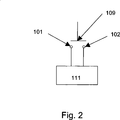
Bei einem Einsatz des beschriebenen Sensors an Bord einer Raumsonde ist die Lage, d. h. der Ort und die Orientierung des Sensors an der Raumsonde, in Bezug auf die Raumsonde bekannt. Mit der von dem Sensor ermittelten Orientierung kann die Orientierung der Raumsonde in Bezug auf das, auf die Raumsonde wie auch den Sensor einwirkende Schwerefeld eindeutig bestimmt werden. In der gezeigten Konfiguration des Sensors können Lagen von 45 Grad in Bezug auf das Schwerkraftrichtung
BezugszeichenlisteLIST OF REFERENCE NUMBERS
- 1–81-8
- KontaktsockelContact socket
- 100100
- Sensorsensor
- 101–108101-108
- elektrische Kontakte, die jeweils vom Gehäuse elektrisch isoliert sindelectrical contacts, each electrically isolated from the housing
- 109109
- Kugel, Polyeder, catalanischer Körper mit elektrisch leitender OberflächeSphere, polyhedron, catalan body with electrically conductive surface
- 110110
- Schwerkraft = Summe aus Gravitationskraft und ZentrifugalkraftGravity = sum of gravitational force and centrifugal force
- 111111
- Auswerteeinheitevaluation
- 112112
- elektrische Leitungenelectric lines
- 113113
- Sensorgehäusesensor housing
- 114a114a
- Position der Kugel, ohne Berührung eines der elektrischen KontaktePosition of the ball, without touching any of the electrical contacts
- 114b114b
- Position der Kugel auf der Innenseite des Sensorgehäuses, die sich durch eine auf die Kugel einwirkende Schwerkraft in Abhängigkeit der Richtung der Schwerkraft ergibtPosition of the ball on the inside of the sensor housing, which results from a gravitational force acting on the ball, depending on the direction of gravity
Claims (7)
Priority Applications (1)
| Application Number | Priority Date | Filing Date | Title |
|---|---|---|---|
| DE201110106986 DE102011106986B3 (en) | 2011-07-05 | 2011-07-05 | Orientation sensor for space probe for determination of orientation of sensor housing in gravitational field in aerospace industry, has evaluation unit i.e. microprocessor, determining position of ball in inner side of sensor housing |
Applications Claiming Priority (1)
| Application Number | Priority Date | Filing Date | Title |
|---|---|---|---|
| DE201110106986 DE102011106986B3 (en) | 2011-07-05 | 2011-07-05 | Orientation sensor for space probe for determination of orientation of sensor housing in gravitational field in aerospace industry, has evaluation unit i.e. microprocessor, determining position of ball in inner side of sensor housing |
Publications (1)
| Publication Number | Publication Date |
|---|---|
| DE102011106986B3 true DE102011106986B3 (en) | 2013-01-03 |
Family
ID=47355395
Family Applications (1)
| Application Number | Title | Priority Date | Filing Date |
|---|---|---|---|
| DE201110106986 Expired - Fee Related DE102011106986B3 (en) | 2011-07-05 | 2011-07-05 | Orientation sensor for space probe for determination of orientation of sensor housing in gravitational field in aerospace industry, has evaluation unit i.e. microprocessor, determining position of ball in inner side of sensor housing |
Country Status (1)
| Country | Link |
|---|---|
| DE (1) | DE102011106986B3 (en) |
Cited By (2)
| Publication number | Priority date | Publication date | Assignee | Title |
|---|---|---|---|---|
| FR3017453A1 (en) * | 2014-02-11 | 2015-08-14 | X Sin | DEVICE FOR OBTAINING INFORMATION NECESSARY FOR A 3D REPRESENTATION OF AN ARTIFICIAL CLIMBING WALL |
| DE102022001662A1 (en) | 2022-05-12 | 2023-11-16 | Diehl Defence Gmbh & Co. Kg | Mechatronic acceleration sensor |
Citations (6)
| Publication number | Priority date | Publication date | Assignee | Title |
|---|---|---|---|---|
| EP0587618B1 (en) * | 1991-05-31 | 1995-09-13 | 3D Instruments Limited | Attitude sensor |
| DE4341918C2 (en) * | 1993-12-06 | 1997-01-30 | Birnbaum Jacek | Electromechanical position change switch |
| JPH11351845A (en) * | 1998-06-05 | 1999-12-24 | Citizen Electronics Co Ltd | Tilt sensor |
| DE10261961A1 (en) * | 2002-03-22 | 2003-10-16 | Hahn Schickard Ges | tilt sensor |
| WO2004020943A1 (en) * | 2002-08-01 | 2004-03-11 | Vishay Infrared Components, Inc. | Tilt sensor and method of making same |
| DE102006016523A1 (en) * | 2006-04-07 | 2007-10-11 | Osram Opto Semiconductors Gmbh | tilt sensor |
-
2011
- 2011-07-05 DE DE201110106986 patent/DE102011106986B3/en not_active Expired - Fee Related
Patent Citations (6)
| Publication number | Priority date | Publication date | Assignee | Title |
|---|---|---|---|---|
| EP0587618B1 (en) * | 1991-05-31 | 1995-09-13 | 3D Instruments Limited | Attitude sensor |
| DE4341918C2 (en) * | 1993-12-06 | 1997-01-30 | Birnbaum Jacek | Electromechanical position change switch |
| JPH11351845A (en) * | 1998-06-05 | 1999-12-24 | Citizen Electronics Co Ltd | Tilt sensor |
| DE10261961A1 (en) * | 2002-03-22 | 2003-10-16 | Hahn Schickard Ges | tilt sensor |
| WO2004020943A1 (en) * | 2002-08-01 | 2004-03-11 | Vishay Infrared Components, Inc. | Tilt sensor and method of making same |
| DE102006016523A1 (en) * | 2006-04-07 | 2007-10-11 | Osram Opto Semiconductors Gmbh | tilt sensor |
Cited By (3)
| Publication number | Priority date | Publication date | Assignee | Title |
|---|---|---|---|---|
| FR3017453A1 (en) * | 2014-02-11 | 2015-08-14 | X Sin | DEVICE FOR OBTAINING INFORMATION NECESSARY FOR A 3D REPRESENTATION OF AN ARTIFICIAL CLIMBING WALL |
| WO2015121588A1 (en) * | 2014-02-11 | 2015-08-20 | X'sin | Device for obtaining information required for a 3d representation of an artificial climbing wall |
| DE102022001662A1 (en) | 2022-05-12 | 2023-11-16 | Diehl Defence Gmbh & Co. Kg | Mechatronic acceleration sensor |
Similar Documents
| Publication | Publication Date | Title |
|---|---|---|
| DE102006058473B4 (en) | Ball switch in a multi-ball switch arrangement | |
| DE3801514C2 (en) | ||
| EP2659233B1 (en) | Sensor system for monitoring surroundings on a mechanical component, and method for actuating and evaluating the sensor system | |
| DE69932967T2 (en) | Pressure sensitive resistance elements using sensor and control devices | |
| DE102015120369B3 (en) | Step mat for securing a technical system | |
| EP0514689A1 (en) | Ball switch for signal identification of one of the directions of inclination of a baseplane | |
| DE102011106986B3 (en) | Orientation sensor for space probe for determination of orientation of sensor housing in gravitational field in aerospace industry, has evaluation unit i.e. microprocessor, determining position of ball in inner side of sensor housing | |
| DE102016122042B4 (en) | Sensor assembly for determining the position of an object | |
| DE10158776B4 (en) | Arrangement for detecting relative movements or relative positions of two objects | |
| DE2356688A1 (en) | ACCIDENT DETECTOR SWITCH FOR VEHICLES | |
| DE19503615C2 (en) | Arrangement for two-dimensional control or for two-dimensional measurement | |
| DE3716623C1 (en) | Position switch | |
| DE102005012883A1 (en) | Switchgear for controlling vehicle, machine and multifunctional equipment, has magnets arranged around magnetic field sensors at fulcrum of actuating rod for tilting actuating rod | |
| DE10225418A1 (en) | Measuring device for measuring positions or movements | |
| EP2941591B1 (en) | Torch with a rotary switch | |
| DE10158416C1 (en) | Multi-ball switch arrangement in layer / plate construction | |
| EP0466021A2 (en) | Acceleration switch with snap-action spring | |
| DE102017212670B4 (en) | operating device | |
| DE102015117080B4 (en) | Magnetic absolute position sensor | |
| DE102016124668A1 (en) | Device for aligning an optical unit of a camera arranged inside a housing and camera with this device | |
| DE102008020133A1 (en) | Device for displaying binary information using electrowetting effect for use in security relevant application, has compartment including control electrodes and volume including basic electrodes, where electrodes lie in different planes | |
| WO2012062800A2 (en) | Movement and position identification sensor | |
| WO2012016953A1 (en) | Passive magnetic switch and method for determining a magnetic field | |
| EP1164612A1 (en) | Acceleration value limiting switch | |
| WO1992009094A1 (en) | Sensor |
Legal Events
| Date | Code | Title | Description |
|---|---|---|---|
| R012 | Request for examination validly filed | ||
| R123 | Application deemed withdrawn due to non-payment of filing fee | ||
| R409 | Internal rectification of the legal status completed | ||
| R409 | Internal rectification of the legal status completed | ||
| R016 | Response to examination communication | ||
| R016 | Response to examination communication | ||
| R082 | Change of representative |
Representative=s name: ROESLER - RASCH - VAN DER HEIDE & PARTNER PATE, DE Representative=s name: ROESLER RASCH & PARTNER PATENT- UND RECHTSANWA, DE Representative=s name: ROESLER SCHICK RASCH PATENTANWAELTE PARTNERSCH, DE |
|
| R016 | Response to examination communication | ||
| R018 | Grant decision by examination section/examining division | ||
| R020 | Patent grant now final |
Effective date: 20130404 |
|
| R119 | Application deemed withdrawn, or ip right lapsed, due to non-payment of renewal fee |