DE102011082554B4 - Method for determining an earth fault current in a three-phase system subject to earth faults - Google Patents
Method for determining an earth fault current in a three-phase system subject to earth faults Download PDFInfo
- Publication number
- DE102011082554B4 DE102011082554B4 DE102011082554.1A DE102011082554A DE102011082554B4 DE 102011082554 B4 DE102011082554 B4 DE 102011082554B4 DE 102011082554 A DE102011082554 A DE 102011082554A DE 102011082554 B4 DE102011082554 B4 DE 102011082554B4
- Authority
- DE
- Germany
- Prior art keywords
- earth
- fault
- current
- phase
- conductor
- Prior art date
- Legal status (The legal status is an assumption and is not a legal conclusion. Google has not performed a legal analysis and makes no representation as to the accuracy of the status listed.)
- Active
Links
Images


Classifications
-
- G—PHYSICS
- G01—MEASURING; TESTING
- G01R—MEASURING ELECTRIC VARIABLES; MEASURING MAGNETIC VARIABLES
- G01R31/00—Arrangements for testing electric properties; Arrangements for locating electric faults; Arrangements for electrical testing characterised by what is being tested not provided for elsewhere
- G01R31/50—Testing of electric apparatus, lines, cables or components for short-circuits, continuity, leakage current or incorrect line connections
- G01R31/52—Testing for short-circuits, leakage current or ground faults
-
- G—PHYSICS
- G01—MEASURING; TESTING
- G01R—MEASURING ELECTRIC VARIABLES; MEASURING MAGNETIC VARIABLES
- G01R31/00—Arrangements for testing electric properties; Arrangements for locating electric faults; Arrangements for electrical testing characterised by what is being tested not provided for elsewhere
- G01R31/08—Locating faults in cables, transmission lines, or networks
- G01R31/081—Locating faults in cables, transmission lines, or networks according to type of conductors
- G01R31/086—Locating faults in cables, transmission lines, or networks according to type of conductors in power transmission or distribution networks, i.e. with interconnected conductors
Abstract
Verfahren zur Bestimmung eines Erdschlussstroms in einem erdschlussbehafteten Drehstromnetz (1) mit drei Leitern (L1, L2, L3), bei dem an einem Speisepunkt des Netzes (1) Leiterströmeund Leiter-Erde-Spannungen der Leiter (L1, L2, L3) gemessen werden, wobei zumindest einmalig ein Gegensystem ( I g_ohne ES ) ohne Erdschluss (ES) aus den im erdschlussfreien Fall gemessenen Leiterströmenberechnet wird, wobei ein Nullsystem ( I n_mit ES ) aus den im Erdschlussfall gemessenen Leiterstrom des fehlerbehafteten Leitersberechnet wird, wobei durch Subtraktion des Nullsystems ( I n_mit ES ) von den im Erdschlussfall gemessenen Leiterströmenein bisymmetrisches System ...Method for determining an earth fault current in a three-phase (L1, L2, L3) three-phase network (1) with earth faults , whereby at least once a negative sequence system (I g_without ES) without earth fault (ES) is calculated from the line currents measured in the case of an earth fault, whereby a zero system (I n_mit ES) is calculated from the line current of the faulty conductor measured in the event of an earth fault, by subtracting the zero system ( I n_mit ES) of the conductor currents measured in the event of an earth fault, a bisymmetric system ...
Description
Die Erfindung betrifft ein Verfahren zur Bestimmung eines Erdschlussstroms in einem erdschlussbehafteten Drehstromnetz.The invention relates to a method for determining an earth fault current in a three-phase system subject to earth-fault.
Die Ansprüche an die Versorgungsqualität mit Elektroenergie sind in den letzten Jahren kontinuierlich gestiegen. Das gilt insbesondere für die Stromversorgung hochproduktiver industrieller Anlagen, aber auch für Haushalt und Gewerbe und bezieht sich sowohl auf eine qualitätsgerechte Versorgung mit Elektroenergie als auch auf eine hohe Zuverlässigkeit bei der unterbrechungsfreien Bereitstellung. Demgegenüber stellen jedoch die Netzbetreiber fest, dass die die Elektroenergiequalität mindernden Abnehmernetzrückwirkungen in einem Umfang zugenommen haben, der den gewohnten sicheren Netzbetrieb gefährden kann.The demands on the supply quality with electric energy have increased continuously in recent years. This applies in particular to the power supply of highly productive industrial plants, but also for households and businesses and relates both to a quality-compliant supply of electrical energy and to a high degree of reliability in the uninterruptible provision. On the other hand, the network operators note that the reduction of customer network effects that reduce the quality of electrical energy has increased to an extent that can jeopardize the usual secure network operation.
Eine hohe Qualität und Zuverlässigkeit der Elektroenergieversorgung kann durch mit Resonanzsternpunkterdung betriebene Netze unter Beachtung wirtschaftlicher und technischer Aspekte erreicht werden, weil bei dem am häufigsten auftretenden Netzfehler, dem einpoligen Erdschluss, keine unmittelbare Unterbrechung der Stromversorgung erforderlich ist. Voraussetzung dafür ist allerdings, dass der Erdschlussreststrom nicht zu unzulässig hohen Berührungsspannungen im Netz führt. Beispielsweise bedeutet dies für ein 20 kV-Netz, dass der Effektivwert des Erdschlussreststroms 60 A nicht überschreitet, damit der Personenschutz sichergestellt ist. Es ist bekannt, dass in Netzen bei einer Verstimmung ν ≤ 2% und einer Dämpfung d ≤ 4% eine Überschreitung des zulässigen Erdschlussreststroms infolge der unvermeidbaren Verzerrung der Versorgungsspannung nicht auszuschließen ist. Diese Gefahr besteht selbst in Netzen, bei denen Grenzwerte für die zulässige Spannungsverzerrung nicht überschritten werden.High quality and reliability of the electric power supply can be achieved by resonant earthing networks, taking into account economic and technical aspects, because the most common mains failure, the single-ended earth fault, does not require immediate interruption of the power supply. The prerequisite for this, however, is that the ground fault residual current does not lead to impermissibly high contact voltages in the network. For example, for a 20 kV network, this means that the RMS residual current does not exceed 60 A to ensure personal safety. It is known that in networks with a detuning ν ≤ 2% and an attenuation d ≤ 4% it is not possible to rule out exceeding the permissible residual earth current due to the unavoidable distortion of the supply voltage. This danger exists even in networks where limits for the permissible voltage distortion are not exceeded.
Ein aus
Die 50 Hz-Komponente kann mittels einer Erdschlussdrosselspule auf möglichst kleine Werte während eines Erdschlusses begrenzt werden, indem die Verstimmung annähernd auf Null gebracht wird. Dies ist möglich, da die Größe des 50 Hz-Erdschlussstroms im erdschlussfreien Netz problemlos bestimmt werden kann und damit der Sollwert für die Einstellung der Erdschlussdrosselspule bekannt ist.The 50 Hz component can be limited by means of a ground fault choke coil to as low a value as possible during a ground fault by bringing the detuning approximately to zero. This is possible because the size of the 50 Hz ground fault current in the ground fault free network can be determined easily and thus the setpoint for setting the ground fault choke coil is known.
Hingegen ist die Bestimmung des 50 Hz-Erdschlussstroms in einem erdschlussbehafteten Netz nicht ohne weiteres möglich. Ein solches Erfordernis ergibt sich dann, wenn in einem Netz im einpoligen Erdschlussfall beispielsweise sogenannte Eingrenzungsschaltungen zur Fehlerortung vorgenommen werden. Dabei werden einzelne Leitungsabgänge ein- oder ausgeschaltet, um den Erdschluss zu lokalisieren. Mit jeder solchen Ein- oder Ausschaltung verändert sich der 50 Hz-Blindstromanteil im Erdschlussstrom. Dabei kann sich der Erdschlussreststrom über einen unzulässig langen Zeitraum erhöhen, da der Sollwert für die Kompensation, beispielsweise der Strom der Erdschlussdrosselspule nicht vorliegt.By contrast, the determination of the 50 Hz ground fault current in a faulty network is not readily possible. Such a requirement arises when, for example, so-called containment circuits for fault location are carried out in a single-pole earth fault network. Single line outlets are switched on or off to locate the ground fault. With each such switching on or off, the 50 Hz reactive current component in the ground fault current changes. In this case, the ground fault current can increase over an impermissibly long period of time, since the setpoint for the compensation, for example, the current of the ground fault choke coil is not present.
Die
Dieses Verfahren ist jedoch sehr aufwändig.However, this process is very complicated.
Die
Aus der
Der Erfindung liegt daher die Aufgabe zu Grunde, ein verbessertes Verfahren zur Bestimmung des Erdschlussstroms in einem erdschlussbehafteten Netz anzugeben.The invention is therefore based on the object to provide an improved method for determining the ground fault current in a faulty network.
Die Aufgabe wird erfindungsgemäß durch ein Verfahren mit den Merkmalen des Anspruchs 1 gelöst.The object is achieved by a method having the features of
Vorteilhafte Ausgestaltungen der Erfindung sind Gegenstand der Unteransprüche.Advantageous embodiments of the invention are the subject of the dependent claims.
In einem erfindungsgemäßen Verfahren zur Bestimmung eines Erdschlussstroms in einem erdschlussbehafteten einseitig gespeisten Drehstromnetz mit drei Leitern, werden an einem Speisepunkt des Netzes Leiterströme und Leiter-Erde-Spannungen der Leiter gemessen. Diese Messung ist zumindest einmalig im erdschlussfreien Netz und wiederholt, beispielsweise periodisch oder kontinuierlich im erdschlussbehafteten Netz erforderlich. Bei mehrfachgespeisten Netzen ist das Verfahren auf alle Einspeisungen anzuwenden und die so ermittelten Erdschlussströme sind zu addieren.In a method according to the invention for determining an earth fault current in a three-phase system with three conductors fed on one side with a short circuit, conductor currents and conductor-earth voltages of the conductors are measured at a feed point of the network. This measurement is at least once in ungeschschlussfreien network and repeatedly, for example, periodically or continuously required in the faulty network. For multi-fed networks, the method must be applied to all feeds and the ground fault currents determined in this way must be added.
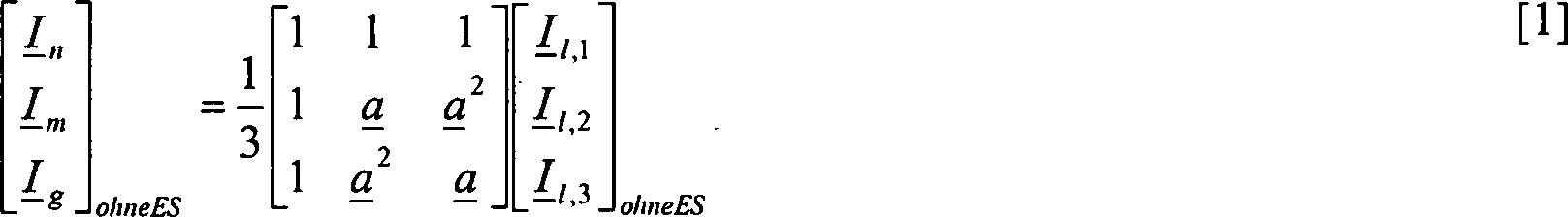
Im Folgenden werden die symmetrischen Komponenten der Einspeiseströme des Drehstromsystems ermittelt. Hierbei werden Phasoren der symmetrischen Komponenten Mitsystem, Gegensystem und Nullsystem aus den Leiterströmen mit Hilfe der Symmetrierungsmatrix bestimmt.In the following, the symmetrical components of the supply currents of the three-phase system are determined. In this case, phasors of the symmetrical components co-system, negative sequence and zero system are determined from the phase currents by means of the balancing matrix.
Zumindest einmalig wird das Gegensystem der im erdschlussfreien Fall gemessenen Leiterströme berechnet. Das Nullsystem aus den im Erdschlussfall gemessenen Leiterströmen, das heißt ein Nullstrom, wird berechnet. Durch Subtraktion des Nullstroms vom im Erdschlussfall gemessenen Leiterstrom des erdschlussbehafteten Leiters wird ein bisymmetrisches System der Leiterströme ermittelt. Das Gegensystem aus den bisymmetrischen Leiterströmen im Erdschlussfall wird berechnet. Der Anteil des die Erdkapazitäten des Netzes speisenden Gegensystemstroms der bisymmetrischen Leiterströme im Erdschlussfall wird durch Subtraktion des Gegensystems im erdschlussfreien Fall vom Gegensystem der bisymmetrischen Leiterströme im Erdschlussfall ermittelt. Eine Grundschwingungskomponente des Erdschlussstroms wird durch Multiplikation des Anteils der die Erdkapazitäten des Netzes speisenden Ströme am Gegensystem mit einem Faktor k bestimmt. Der Faktor k ist bei einem Drehstromnetz mit drei Leitern
Dem Verfahren liegen folgende Annahmen zugrunde:
- – Im Erdschlussfall ist der Quotient aus dem Gegensystem zum Mitsystem der die Erdkapazitäten speisenden Ströme konstant und Bestandteil der im Einspeisetransformator fließenden Leiterströme.
- – Das Gegensystem der durch Abnehmerlasten des Drehstromnetzes bedingten Ströme ohne den Anteil des Gegensystems der die Erdkapazitäten speisenden Ströme ist sehr gleichmäßig und deutlich kleiner als der Anteil des Gegensystems der die Erdkapazitäten speisenden Ströme.
- – Aus der Änderung des Gegensystems der Leiterströme bei Eintritt des Erdschlusses kann auf den kapazitiven Erdschlussstrom geschlossen werden.
- – Aus der Änderung des Gegensystems der Leiterströme während des Erdschlusses kann auf die Änderung des kapazitiven Erdschlussstroms geschlossen werden.
- - In the event of a ground fault, the quotient from the negative sequence system to the positive sequence of the currents supplying the earth capacitors is constant and a component of the phase currents flowing in the supply transformer.
- - The negative sequence of currents caused by consumer loads of the three-phase network without the contribution of the negative sequence of the currents feeding the earth capacitances is very uniform and significantly smaller than the proportion of the negative sequence of the currents feeding the earth capacitances.
- - The capacitive earth fault current can be deduced from the change in the negative sequence of the phase currents when the ground fault occurs.
- - It can be concluded from the change of the negative sequence of the phase currents during the earth fault on the change of the capacitive ground fault current.
Mittels des erfindungsgemäßen Verfahrens kann eine kompensatorische Einrichtung zur Begrenzung des Erdschlussstroms abhängig von der ermittelten Grundschwingungskomponente des Erdschlussstroms so gesteuert und/oder geregelt werden, dass der Erdschlussstrom auf einen vorgegebenen Wert verringert wird.By means of the method according to the invention, a compensatory device for limiting the ground fault current can be controlled and / or regulated as a function of the determined fundamental component of the ground fault current such that the ground fault current is reduced to a predetermined value.
Beispielsweise kann die Induktivität einer Erdschlussdrosselspule durch mechanisches Verstellen ihres Kerns zur Kompensation der Grundschwingungskomponente des Erdschlussstroms verändert werden.For example, the inductance of a ground fault choke coil can be changed by mechanically adjusting its core to compensate for the fundamental component of the ground fault current.
Üblich ist auch die Anwendung von zur Erdschlussdrosselspule parallelgeschalteten Kondensatoren zur schnellen Änderung des 50-Hz-Kompensationsstroms.It is also common to use capacitors connected in parallel with the ground fault choke coil to quickly change the 50 Hz compensation current.
Vorzugsweise wird jedoch als kompensatorische Einrichtung ein fünfphasiger aktiver Kompensator mit Anschluss am Speisepunkt des Drehstromnetzes verwendet. Auf diese Weise kann besonders flexibel und schnell auf Änderungen des Gegensystems reagiert werden, beispielsweise wenn zur Ortung des Erdschlusses einzelne Leitungsabgänge des Drehstromnetzes ein- oder ausgeschaltet werden. Preferably, however, a five-phase active compensator connected to the feed point of the three-phase network is used as the compensatory device. In this way, it is possible to react particularly flexibly and quickly to changes in the negative sequence system, for example if individual line outlets of the three-phase network are switched on or off to locate the ground fault.
Vorzugsweise ist mindestens ein Sternpunkt des Drehstromnetzes auf einer Sekundärseite mindestens eines Einspeisetransformators über eine Erdschlussdrossel mit einem Erdpunkt verbunden. Der fünfphasige aktive Kompensator umfasst steuerbare elektronische Schalter, wobei für jeden der Leiter des Drehstromnetzes je zwei Schalter vorgesehen sind, über die der Leiter mit Eingängen einer Schaltbrücke verbindbar ist, als deren Brückenzweig ein der Erdschlussdrossel parallel geschalteter erster Koppeltransformator oder eine Hilfswicklung der Erdschlussdrossel angeschlossen wird, so dass der fünfphasige Kompensator induktiv mit dem Erdpunkt der Erdschlussdrossel verbunden ist, wobei zwischen den Eingängen der Schaltbrücke mindestens ein Kondensator vorgesehen ist. Der auf diese Weise als aktiver Filterkreis gestaltete fünfphasige aktive Kompensator ist prinzipiell flexibler an eine veränderte Topologie des Drehstromnetzes anpassbar als ein passiver Filterkreis.Preferably, at least one star point of the three-phase system is connected to a ground point on a secondary side of at least one supply transformer via a ground fault choke. The five-phase active compensator comprises controllable electronic switches, two switches being provided for each of the conductors of the three-phase network, via which the conductor can be connected to inputs of a switching bridge, as the bridge branch of which a first coupling transformer connected in parallel with the grounding choke or an auxiliary winding of the grounding choke is connected in that the five-phase compensator is inductively connected to the earth point of the ground fault choke, wherein at least one capacitor is provided between the inputs of the switching bridge. The five-phase active compensator configured in this way as an active filter circuit is, in principle, more flexibly adaptable to a modified topology of the three-phase network than a passive filter circuit.
Mit dem parallel zur Erdschlussdrossel geschalteten Koppeltransformator kann durch den mittels elektronisch steuerbarer Schalter gebildeten und als Filterkreis wirkenden Stromrichter ein beliebiger Wechselstrom eingespeist werden, um sowohl Fehlerströme infolge des Erdfehlers als auch Unsymmetrien sowohl im Bereich einer Grundschwingung als auch im Bereich von Oberschwingungen zu kompensieren. Im Falle der Nutzung der Leitungshilfswicklung der Erdschlussdrossel, die meist ohnehin vorhanden ist, wird statt eines Stroms eine Spannung eingespeist, die aber letztlich den Strom im Erdpunkt bestimmt.With the coupling transformer connected in parallel with the ground-fault choke, an arbitrary alternating current can be fed in by means of the electronically controllable switch and acting as a filter circuit in order to compensate for fault currents as a result of the earth fault as well as asymmetries both in the region of a fundamental oscillation and in the region of harmonics. In the case of using the auxiliary line winding of the earth fault choke, which is usually present anyway, a voltage is fed instead of a current, but ultimately determines the current in the earth point.
Der fünfphasige aktive Kompensator kann auch in einem Stromnetz mit mehr oder weniger als drei Außenleitern angewandt werden, beispielsweise in einem Bahnstromnetz, in dem zwei gegen Erde isolierte Leiter vorgesehen sind.The five-phase active compensator can also be used in a power network with more or less than three outer conductors, for example in a traction current network, in which two insulated against earth conductors are provided.
Die Schaltbrücke kann vier steuerbare elektronische Schalter oder zwei steuerbare elektronische Schalter und zwei Kondensatoren umfassen.The switching bridge may comprise four controllable electronic switches or two controllable electronic switches and two capacitors.
Der fünfphasige aktive Kompensator kann auch benutzt werden, um dem Drehstromnetz im erdfehlerfreien Betrieb einen Nullstrom aufzuprägen, beispielsweise in einem Bereich von 0.1 Hz bis 2000 Hz, mittels dessen frequenzabhängige Nulladmittanzen ermittelt werden, die als Sollwert in einer Erfassungseinrichtung gespeichert werden. Durch Vergleich mit im Falle eines einpoligen Erdschlusses auf gleiche Weise ermittelten Nulladmittanzen mit dem Sollwert kann der Abstand eines Ortes des Erdschlusses vom fünfphasigen aktiven Kompensator bestimmt werden. In den Fällen, bei denen beispielsweise im Erdschlussfall infolge einer fehlerhaften Bewertung der Eingrenzungsschaltungen irrtümlich ein fehlerfreier Abgang ausgeschaltet wird, wird die nunmehr veränderte Kompensationsleistung, die nicht kurzfristig durch die Erdschlussdrossel zur Verfügung gestellt werden kann oder wird, vom fünfphasigen aktiven Kompensator übernommen.The five-phase active compensator can also be used to impose a zero current on the three-phase network in earth fault-free operation, for example in a range of 0.1 Hz to 2000 Hz, by means of which frequency-dependent zero admittances are stored, which are stored as setpoint in a detection device. By comparison with zero setpoint values determined in the same way in the case of a single-pole earth fault, the distance of a location of the ground fault from the five-phase active compensator can be determined. In cases where, for example, an error-free output is erroneously switched off in case of an earth fault due to an incorrect evaluation of the limiting circuits, the now changed compensation power, which can not be provided by the short-circuit reactor in the short term, is taken over by the five-phase active compensator.
In einer weiteren Ausführungsform sind die Leiter mit den Schaltern des fünfphasigen aktiven Kompensators über einen zweiten Koppeltransformator induktiv verbunden. Auf diese Weise sind elektronische Schalter mit herkömmlichen Sperrspannungen verwendbar, auch wenn im Drehstromnetz höhere Spannungen verwendet werden. Beispielsweise kann das Drehstromnetz als ein Mittelspannungsnetz mit einer Spannung von 20 kV ausgebildet sein, während die elektronischen Schalter nur für Sperrspannungen von etwa 1 kV ausgelegt sind. Der zweite Koppeltransformator ist insbesondere als ein dreiphasiger Koppeltransformator ausgebildet.In a further embodiment, the conductors are inductively connected to the switches of the five-phase active compensator via a second coupling transformer. In this way, electronic switches with conventional blocking voltages can be used, even if higher voltages are used in the three-phase network. For example, the three-phase network can be designed as a medium-voltage network with a voltage of 20 kV, while the electronic switches are designed only for reverse voltages of about 1 kV. The second coupling transformer is designed in particular as a three-phase coupling transformer.
Der fünfphasige aktive Kompensator kann zusätzlich direkt mit einem Erdpunkt verbunden sein:
Der fünfphasige aktive Kompensator und seine Steuerung sind vorzugsweise als ein mehrfrequenter Filterkreis so ausgebildet, dass er bei mindestens einer ersten Frequenz eine Saugkreisfunktion übernimmt und bei mindestens einer zweiten Frequenz als Sperrkreis wirkt. Durch eine mehrphasige, insbesondere beim Drehstromnetz dreiphasige, aktive und zum entsprechenden Fehlerstromanteil gegenphasige Einspeisung von mindestens einem harmonischen Stromanteil wird der Fehlerstromanteil unterdrückt. Eine einphasige, aktive und zu einem Fehlerstromanteil, vorzugsweise zum Grundschwingungsanteil des Fehlerstroms, gegenphasige Einspeisung eines Stromanteils, erfolgt mit dem Ziel, den Grundschwingungsanteil, beispielsweise 50 Hz, des Fehlerstroms (Blind- und Wirkreststrom) und/oder weitere Frequenzanteile im Fehlerstrom zu unterdrücken. Auf diese Weise wird vermieden, dass ein Stromfluss bei dieser zweiten Frequenz über eine Fehlerstelle zustande kommt, so dass keine zusätzlichen unerwünschten Berührungs- und Schrittspannungen an der Fehlerstelle auftreten.The five-phase active compensator can additionally be directly connected to a ground point:
The five-phase active compensator and its control are preferably designed as a multi-frequency filter circuit so that it assumes a Saugkreisfunktion at least one first frequency and acts at least one second frequency as a blocking circuit. By a multi-phase, in particular three-phase three-phase, active and the corresponding fault current component in phase opposition of at least one harmonic current component of the fault current component is suppressed. A single-phase, active and an error current component, preferably the fundamental component of the fault current, in-phase supply of a current component, is carried out with the aim to suppress the fundamental component, such as 50 Hz, the fault current (reactive and Wirkreststrom) and / or other frequency components in the fault current. In this way, it is avoided that a current flow at this second frequency over a fault occurs, so that no additional undesirable contact and step voltages occur at the fault.
Die zu kompensierende Frequenzkomponente bei der ersten Frequenz ist vorzugsweise eine Harmonische der Grundfrequenz, insbesondere die fünfte oder die siebte Harmonische, da deren Anteil an dem Fehlerstrom besonders hoch sein kann. Beispielsweise bei einer Grundfrequenz von 50 Hz, wie in Europa und weiten Teilen der Welt üblich, entspricht die fünfte Harmonische 250 Hz und die siebte Harmonische 350 Hz. The frequency component to be compensated at the first frequency is preferably a harmonic of the fundamental frequency, in particular the fifth or the seventh harmonic, since their share of the fault current can be particularly high. For example, at a fundamental frequency of 50 Hz, as is common in Europe and much of the world, the fifth harmonic corresponds to 250 Hz and the seventh harmonic to 350 Hz.
Die zweite Frequenz, bei der ein Stromfluss über den Filterkreis unterbunden wird, ist vorzugsweise die Grundfrequenz des Drehstromnetzes.The second frequency at which a current flow through the filter circuit is prevented is preferably the fundamental frequency of the three-phase network.
Die elektronischen Schalter sind vorzugsweise als steuerbare Halbleiterbauelemente, wie IGBTs (Insulated Gate Bipolar Transistor) ausgebildet. Sie bieten den Vorteil schnellerer Schaltzeiten verglichen mit herkömmlichen Schaltern. Ein den Fehlerstrom an der Erdfehlerstelle zumindest partiell kompensierender Stromfluss wird dann vorzugsweise durch gesteuertes, gepulstes Schalten von Gleichspannungsquellen, insbesondere den Kondensatoren in den Strompfad des fünfphasigen aktiven Kompensators verursacht. Der fünfphasige aktive Kompensator reagiert schneller als eine veränderbare voreingestellte Erdschlussdrosselspule auf Änderungen der Erdkapazität des Drehstromnetzes, die eine Erhöhung des Fehlerstroms an der Erdfehlerstelle bewirken kann. Dies geschieht beispielsweise dann, wenn bei einem detektierten Erdfehler in einem verzweigten Drehstromnetz der Erdfehler in einem falschen Abzweig lokalisiert und dieser Abzweig daraufhin abgeschaltet wird, während der vom Erdfehler betroffene Abzweig noch unter Spannung bleibt.The electronic switches are preferably designed as controllable semiconductor components, such as IGBTs (Insulated Gate Bipolar Transistor). They offer the advantage of faster switching times compared to conventional switches. A current flow that at least partially compensates the fault current at the ground fault location is then preferably caused by controlled, pulsed switching of DC voltage sources, in particular the capacitors, into the current path of the five-phase active compensator. The five-phase active compensator responds faster than a variable pre-set ground fault choke coil to changes in the earth capacitance of the three-phase system, which can cause an increase in fault current at the earth fault location. This occurs, for example, when a detected earth fault in a branched three-phase network, the earth fault located in a wrong branch and this branch is then turned off, while the affected by the earth fault branch still remains under tension.
Der fünfphasige aktive Kompensator kann auch dann verwendet werden, wenn auf keinem der Leiter ein Erdschluss vorliegt, insbesondere so, dass ein Strom zum Fließen kommt, der im Drehstromnetz vorhandene Blindleistung, wie z. B. Deformationen der Versorgungsspannung (Verzerrung, Unsymmetrie, Einbrüche, etc.) oder eine Verschiebungsblindleistung auf vorgegebene Werte begrenzt oder reduziert.The five-phase active compensator can also be used if there is no ground fault on any of the conductors, in particular in such a way that a current flows, the reactive power present in the three-phase system, such as the reactive power. B. Deformations of the supply voltage (distortion, imbalance, burglary, etc.) or a shift reactive power limited to predetermined values or reduced.
Ausführungsbeispiele der Erfindung werden im Folgenden anhand von Zeichnungen näher erläutert.Embodiments of the invention are explained in more detail below with reference to drawings.
Darin zeigen:Show:
Einander entsprechende Teile sind in allen Figuren mit den gleichen Bezugszeichen versehen.Corresponding parts are provided in all figures with the same reference numerals.
Über den ersten Koppeltransformator
Die Schalter
In
In
Um einen Erdschluss E zu lokalisieren, werden einzelne Abgänge des Drehstromnetzes
Zur Bestimmung des Erdschlussstroms im erdschlussbehafteten Drehstromnetz wird daher folgendes Verfahren angewandt: An einem Speisepunkt, beispielsweise dem Einspeisetransformator 
Es werden folgende Schritte ausgeführt:
Zumindest einmalige Bestimmung des Gegensystemstroms ohne Erdschluss 
![]()
At least one-time determination of the negative sequence current without ground fault ![]()
Der Gegensystemstrom
Im nächsten Schritt wird der Strom des Nullsystems 

Der mit einem Faktor k = 3 multiplizierte Wert des Nullsystemstroms
Im nächsten Schritt wird durch Subtraktion des Stroms im Nullsystem 


Das bisymmetrische System
Im nächsten Schritt wird das Gegensystem der Ströme 

Im nächsten Schritt wird der Anteil des die Erdkapazitäten speisenden Stroms des Gegensystems
Schließlich wird eine Grundschwingungskomponente ICE des Erdschlussstroms durch Multiplikation des Anteils der die Erdkapazitäten des Netzes speisenden Ströme
Die ermittelte Grundschwingungskomponente ICE des Erschlussstroms wird dann zur Steuerung des fünfphasigen aktiven Kompensators
Das Drehstromnetz
Statt des Drehstromnetzes
Das Verfahren kann auch in Netzen mit mehr oder weniger als drei Außenleitern und/oder bei von 50 Hz abweichenden Grundfrequenzen angewendet werden. Der Faktor k ist dann entsprechend der Anzahl der Außenleiter zu wählen.The method can also be used in networks with more or less than three outer conductors and / or at 50 Hz different fundamental frequencies. The factor k is then to be selected according to the number of outer conductors.
Der fünfphasige aktive Kompensator
Die Einrichtung kann auch verwendet werden, um die Erdschlussstelle E zu lokalisieren. Hierzu wird der fünfphasige aktive Kompensator
BezugszeichenlisteLIST OF REFERENCE NUMBERS
- 11
- DrehstromnetzThree-phase system
- 22
- EinspeisetransformatorSupply transformer
- 33
- Sternpunktstar point
- 44
- ErdschlussdrosselErdschlussdrossel
- 4.14.1
- Hilfswicklungauxiliary winding
- 5.1, 5.25.1, 5.2
- Erdpunktground point
- 66
- fünfphasiger aktiver Kompensatorfive-phase active compensator
- 77
- Schalterswitch
- 88th
- Schaltbrückejumper
- 8.1, 8.28.1, 8.2
- Eingangentrance
- 8.3, 8.48.3, 8.4
- Ausgangoutput
- 1010
- erster Koppeltransformatorfirst coupling transformer
- 1111
- zweiter Koppeltransformatorsecond coupling transformer
- CL1, CL2, CL3CL1, CL2, CL3
- Erdkapazitätearth capacitance
- C1, C2C1, C2
- Kondensatorcapacitor
- Ee
- ErdschlussGround Fault
- HSHS
- HochspannungsseiteHigh voltage side
- L1, L2, L3L1, L2, L3
- Leiterladder
- MSMS
- MittelspannungsseiteMedium voltage side
Claims (7)


Priority Applications (1)
| Application Number | Priority Date | Filing Date | Title |
|---|---|---|---|
| DE102011082554.1A DE102011082554B4 (en) | 2011-09-12 | 2011-09-12 | Method for determining an earth fault current in a three-phase system subject to earth faults |
Applications Claiming Priority (1)
| Application Number | Priority Date | Filing Date | Title |
|---|---|---|---|
| DE102011082554.1A DE102011082554B4 (en) | 2011-09-12 | 2011-09-12 | Method for determining an earth fault current in a three-phase system subject to earth faults |
Publications (2)
| Publication Number | Publication Date |
|---|---|
| DE102011082554A1 DE102011082554A1 (en) | 2013-03-14 |
| DE102011082554B4 true DE102011082554B4 (en) | 2014-04-10 |
Family
ID=47739951
Family Applications (1)
| Application Number | Title | Priority Date | Filing Date |
|---|---|---|---|
| DE102011082554.1A Active DE102011082554B4 (en) | 2011-09-12 | 2011-09-12 | Method for determining an earth fault current in a three-phase system subject to earth faults |
Country Status (1)
| Country | Link |
|---|---|
| DE (1) | DE102011082554B4 (en) |
Cited By (1)
| Publication number | Priority date | Publication date | Assignee | Title |
|---|---|---|---|---|
| WO2015180002A1 (en) * | 2014-05-29 | 2015-12-03 | 国家电网公司 | Apparatus for judging failure of iron core and clamping part of ultra-high voltage electric reactor, and processing and eliminating same online |
Families Citing this family (2)
| Publication number | Priority date | Publication date | Assignee | Title |
|---|---|---|---|---|
| EP3336563A1 (en) * | 2013-06-26 | 2018-06-20 | Fuji Electric FA Components & Systems Co. Ltd. | Insulation monitoring device |
| CN111769534B (en) * | 2020-02-06 | 2022-06-07 | 云南电网有限责任公司电力科学研究院 | Voltage adjusting method and device of power supply ground fault current compensation system |
Citations (2)
| Publication number | Priority date | Publication date | Assignee | Title |
|---|---|---|---|---|
| US20030197989A1 (en) * | 2002-04-05 | 2003-10-23 | Smc Electrical Products, Inc. | Method and apparatus for high impedance grounding of medium voltage AC drives |
| DE10261837A1 (en) * | 2002-12-20 | 2004-03-25 | Siemens Ag | Current differential protection for transformer in multi-phase supply network, involves using derived currents to form difference currents for isolated network, and corrected currents for earthed network |
Family Cites Families (2)
| Publication number | Priority date | Publication date | Assignee | Title |
|---|---|---|---|---|
| DE10146294C1 (en) | 2001-09-19 | 2003-07-17 | Edc Gmbh | Network compensation determination method for tuning Petersen coil uses equations obtained from measured phase voltages and line currents for calculation of capacitive zero current |
| DE102006021888B3 (en) | 2006-05-11 | 2007-11-29 | H. Kleinknecht Gmbh & Co. Kg | Arrangement and method for compensating a fault current in the event of a ground fault |
-
2011
- 2011-09-12 DE DE102011082554.1A patent/DE102011082554B4/en active Active
Patent Citations (2)
| Publication number | Priority date | Publication date | Assignee | Title |
|---|---|---|---|---|
| US20030197989A1 (en) * | 2002-04-05 | 2003-10-23 | Smc Electrical Products, Inc. | Method and apparatus for high impedance grounding of medium voltage AC drives |
| DE10261837A1 (en) * | 2002-12-20 | 2004-03-25 | Siemens Ag | Current differential protection for transformer in multi-phase supply network, involves using derived currents to form difference currents for isolated network, and corrected currents for earthed network |
Cited By (1)
| Publication number | Priority date | Publication date | Assignee | Title |
|---|---|---|---|---|
| WO2015180002A1 (en) * | 2014-05-29 | 2015-12-03 | 国家电网公司 | Apparatus for judging failure of iron core and clamping part of ultra-high voltage electric reactor, and processing and eliminating same online |
Also Published As
| Publication number | Publication date |
|---|---|
| DE102011082554A1 (en) | 2013-03-14 |
Similar Documents
| Publication | Publication Date | Title |
|---|---|---|
| EP1855366B1 (en) | Circuit and method to compensate the fault current during a ground fault | |
| EP2372857B1 (en) | Determination of the proportion of differential current made up of faulty current | |
| EP0166954B1 (en) | Method for the reduction of dynamic overvoltages in an alternating current grid system | |
| EP2530841B1 (en) | Device and method for protecting a mains filter | |
| EP3485549B1 (en) | Method for preventing hazardous ground fault of a higher frequency for an electric drive system | |
| EP3059828A1 (en) | Device and method for detecting residual curent | |
| WO2015007779A1 (en) | Method and circuit arrangement with means for a leakage current compensation in a photovoltaic system with multiple differential current sensors | |
| DE102015214615A1 (en) | Method and apparatus for extended insulation fault location with multifunctional test current | |
| DE112018005677T5 (en) | METHOD AND DEVICE FOR DETECTING ERRORS AND PROTECTING ELECTRICAL NETWORKS | |
| EP3979478A1 (en) | Machines with power-electronic energy converters and discharge current compensation and installation | |
| EP2367272B1 (en) | Inverter | |
| DE102011082554B4 (en) | Method for determining an earth fault current in a three-phase system subject to earth faults | |
| DE102010060333B4 (en) | Decentralized generation plant, in particular wind energy plant, test circuit and test method | |
| DE102008024348B4 (en) | Method for reducing pulsed earth currents on a large electric device and compensating circuit for earth current displacement | |
| DE102019127579B3 (en) | Monitoring device for leakage currents | |
| EP2362514B1 (en) | Device for reducing earth leakage current | |
| DE10355086B4 (en) | Method for determining the ohmic insulation resistance of a grounded AC network | |
| DE102021112016B3 (en) | Method and device for determining a ground fault direction | |
| DE102019129413B4 (en) | Compensation device for leakage currents | |
| DE4418124A1 (en) | Device for recognising insulation deterioration on power-supply cables | |
| DE2735756A1 (en) | Earth leakage detection in compensated power networks - uses superimposed AF signals and reactive power relay detector | |
| DE102020105832B4 (en) | Method and device for compensating for a leakage current | |
| EP0053229B1 (en) | Method and circuit for detecting and breaking disturbing electric arcs | |
| DE10146294C1 (en) | Network compensation determination method for tuning Petersen coil uses equations obtained from measured phase voltages and line currents for calculation of capacitive zero current | |
| DE102020004825A1 (en) | Device and method for compensating for leakage currents when charging an electrical energy store |
Legal Events
| Date | Code | Title | Description |
|---|---|---|---|
| R012 | Request for examination validly filed | ||
| R016 | Response to examination communication | ||
| R018 | Grant decision by examination section/examining division | ||
| R020 | Patent grant now final | ||
| R020 | Patent grant now final |
Effective date: 20150113 |
|
| R081 | Change of applicant/patentee |
Owner name: KEMA-IEV INGENIEURUNTERNEHMEN FUER ENERGIEVERS, DE Free format text: FORMER OWNERS: H. KLEINKNECHT GMBH & CO. KG, 98693 ILMENAU, DE; E.ON EDIS AG, 15517 FUERSTENWALDE, DE; KEMA-IEV INGENIEURUNTERNEHMEN FUER ENERGIEVERSORGUNG GMBH, 01217 DRESDEN, DE Owner name: E.ON EDIS AG, DE Free format text: FORMER OWNERS: H. KLEINKNECHT GMBH & CO. KG, 98693 ILMENAU, DE; E.ON EDIS AG, 15517 FUERSTENWALDE, DE; KEMA-IEV INGENIEURUNTERNEHMEN FUER ENERGIEVERSORGUNG GMBH, 01217 DRESDEN, DE Owner name: H. KLEINKNECHT & CO. GMBH, DE Free format text: FORMER OWNERS: H. KLEINKNECHT GMBH & CO. KG, 98693 ILMENAU, DE; E.ON EDIS AG, 15517 FUERSTENWALDE, DE; KEMA-IEV INGENIEURUNTERNEHMEN FUER ENERGIEVERSORGUNG GMBH, 01217 DRESDEN, DE Owner name: E.DIS NETZ GMBH, DE Free format text: FORMER OWNERS: H. KLEINKNECHT GMBH & CO. KG, 98693 ILMENAU, DE; E.ON EDIS AG, 15517 FUERSTENWALDE, DE; KEMA-IEV INGENIEURUNTERNEHMEN FUER ENERGIEVERSORGUNG GMBH, 01217 DRESDEN, DE |
|
| R082 | Change of representative |
Representative=s name: LIEDTKE, MARKUS, DIPL.-ING., DE |
|
| R081 | Change of applicant/patentee |
Owner name: H. KLEINKNECHT & CO. GMBH, DE Free format text: FORMER OWNERS: E.ON EDIS AG, 15517 FUERSTENWALDE, DE; H. KLEINKNECHT & CO. GMBH, 57080 SIEGEN, DE; KEMA-IEV INGENIEURUNTERNEHMEN FUER ENERGIEVERSORGUNG GMBH, 01217 DRESDEN, DE Owner name: E.DIS NETZ GMBH, DE Free format text: FORMER OWNERS: E.ON EDIS AG, 15517 FUERSTENWALDE, DE; H. KLEINKNECHT & CO. GMBH, 57080 SIEGEN, DE; KEMA-IEV INGENIEURUNTERNEHMEN FUER ENERGIEVERSORGUNG GMBH, 01217 DRESDEN, DE |
|
| R082 | Change of representative |
Representative=s name: LIEDTKE, MARKUS, DIPL.-ING., DE |
|
| R079 | Amendment of ipc main class |
Free format text: PREVIOUS MAIN CLASS: G01R0031020000 Ipc: G01R0031500000 |