DE102011052233A1 - Fiberoptic carbon dioxide purity sensor assembly and system - Google Patents
Fiberoptic carbon dioxide purity sensor assembly and system Download PDFInfo
- Publication number
- DE102011052233A1 DE102011052233A1 DE102011052233A DE102011052233A DE102011052233A1 DE 102011052233 A1 DE102011052233 A1 DE 102011052233A1 DE 102011052233 A DE102011052233 A DE 102011052233A DE 102011052233 A DE102011052233 A DE 102011052233A DE 102011052233 A1 DE102011052233 A1 DE 102011052233A1
- Authority
- DE
- Germany
- Prior art keywords
- fiber
- gas
- purity
- thermally conductive
- sensor assembly
- Prior art date
- Legal status (The legal status is an assumption and is not a legal conclusion. Google has not performed a legal analysis and makes no representation as to the accuracy of the status listed.)
- Withdrawn
Links
- CURLTUGMZLYLDI-UHFFFAOYSA-N Carbon dioxide Chemical compound O=C=O CURLTUGMZLYLDI-UHFFFAOYSA-N 0.000 title claims abstract description 38
- 229910002092 carbon dioxide Inorganic materials 0.000 title claims abstract description 19
- 239000001569 carbon dioxide Substances 0.000 title claims abstract description 19
- 239000000835 fiber Substances 0.000 claims abstract description 180
- 239000007789 gas Substances 0.000 claims description 225
- 230000003287 optical effect Effects 0.000 claims description 29
- PXHVJJICTQNCMI-UHFFFAOYSA-N Nickel Chemical compound [Ni] PXHVJJICTQNCMI-UHFFFAOYSA-N 0.000 claims description 21
- 239000000463 material Substances 0.000 claims description 12
- 229910052759 nickel Inorganic materials 0.000 claims description 11
- 239000003017 thermal stabilizer Substances 0.000 claims description 11
- 239000010949 copper Substances 0.000 claims description 8
- 238000003491 array Methods 0.000 claims description 7
- 239000004020 conductor Substances 0.000 claims description 7
- 229910052802 copper Inorganic materials 0.000 claims description 7
- 238000012545 processing Methods 0.000 claims description 7
- RYGMFSIKBFXOCR-UHFFFAOYSA-N Copper Chemical compound [Cu] RYGMFSIKBFXOCR-UHFFFAOYSA-N 0.000 claims description 6
- 229910052782 aluminium Inorganic materials 0.000 claims description 6
- XAGFODPZIPBFFR-UHFFFAOYSA-N aluminium Chemical compound [Al] XAGFODPZIPBFFR-UHFFFAOYSA-N 0.000 claims description 5
- KDLHZDBZIXYQEI-UHFFFAOYSA-N Palladium Chemical compound [Pd] KDLHZDBZIXYQEI-UHFFFAOYSA-N 0.000 claims description 4
- 229910052737 gold Inorganic materials 0.000 claims description 4
- 239000010931 gold Substances 0.000 claims description 4
- BASFCYQUMIYNBI-UHFFFAOYSA-N platinum Chemical compound [Pt] BASFCYQUMIYNBI-UHFFFAOYSA-N 0.000 claims description 4
- OKTJSMMVPCPJKN-UHFFFAOYSA-N Carbon Chemical compound [C] OKTJSMMVPCPJKN-UHFFFAOYSA-N 0.000 claims description 3
- 229910052799 carbon Inorganic materials 0.000 claims description 3
- 229910052719 titanium Inorganic materials 0.000 claims description 3
- 239000010936 titanium Substances 0.000 claims description 3
- VYZAMTAEIAYCRO-UHFFFAOYSA-N Chromium Chemical compound [Cr] VYZAMTAEIAYCRO-UHFFFAOYSA-N 0.000 claims description 2
- BQCADISMDOOEFD-UHFFFAOYSA-N Silver Chemical compound [Ag] BQCADISMDOOEFD-UHFFFAOYSA-N 0.000 claims description 2
- RTAQQCXQSZGOHL-UHFFFAOYSA-N Titanium Chemical compound [Ti] RTAQQCXQSZGOHL-UHFFFAOYSA-N 0.000 claims description 2
- 239000011651 chromium Substances 0.000 claims description 2
- 229910052804 chromium Inorganic materials 0.000 claims description 2
- 229910017052 cobalt Inorganic materials 0.000 claims description 2
- 239000010941 cobalt Substances 0.000 claims description 2
- GUTLYIVDDKVIGB-UHFFFAOYSA-N cobalt atom Chemical compound [Co] GUTLYIVDDKVIGB-UHFFFAOYSA-N 0.000 claims description 2
- 230000007797 corrosion Effects 0.000 claims description 2
- 238000005260 corrosion Methods 0.000 claims description 2
- 229910003460 diamond Inorganic materials 0.000 claims description 2
- 239000010432 diamond Substances 0.000 claims description 2
- 230000003628 erosive effect Effects 0.000 claims description 2
- 239000011152 fibreglass Substances 0.000 claims description 2
- PCHJSUWPFVWCPO-UHFFFAOYSA-N gold Chemical compound [Au] PCHJSUWPFVWCPO-UHFFFAOYSA-N 0.000 claims description 2
- AMGQUBHHOARCQH-UHFFFAOYSA-N indium;oxotin Chemical class [In].[Sn]=O AMGQUBHHOARCQH-UHFFFAOYSA-N 0.000 claims description 2
- 239000002105 nanoparticle Substances 0.000 claims description 2
- 230000003647 oxidation Effects 0.000 claims description 2
- 238000007254 oxidation reaction Methods 0.000 claims description 2
- 229910052763 palladium Inorganic materials 0.000 claims description 2
- 229910052697 platinum Inorganic materials 0.000 claims description 2
- 229910052709 silver Inorganic materials 0.000 claims description 2
- 239000004332 silver Substances 0.000 claims description 2
- 238000005253 cladding Methods 0.000 abstract description 8
- 238000006243 chemical reaction Methods 0.000 description 28
- 238000010586 diagram Methods 0.000 description 25
- 230000035945 sensitivity Effects 0.000 description 20
- 230000004044 response Effects 0.000 description 17
- 238000001514 detection method Methods 0.000 description 14
- 238000005259 measurement Methods 0.000 description 12
- 238000000034 method Methods 0.000 description 11
- 239000013307 optical fiber Substances 0.000 description 6
- 238000012546 transfer Methods 0.000 description 6
- 239000000203 mixture Substances 0.000 description 5
- 238000009834 vaporization Methods 0.000 description 5
- 230000008016 vaporization Effects 0.000 description 5
- VYPSYNLAJGMNEJ-UHFFFAOYSA-N Silicium dioxide Chemical compound O=[Si]=O VYPSYNLAJGMNEJ-UHFFFAOYSA-N 0.000 description 4
- 229910002091 carbon monoxide Inorganic materials 0.000 description 4
- 230000007423 decrease Effects 0.000 description 4
- 239000012769 display material Substances 0.000 description 4
- 230000008569 process Effects 0.000 description 4
- 230000000712 assembly Effects 0.000 description 3
- 238000000429 assembly Methods 0.000 description 3
- 239000010408 film Substances 0.000 description 3
- 238000010438 heat treatment Methods 0.000 description 3
- 238000012544 monitoring process Methods 0.000 description 3
- 230000035484 reaction time Effects 0.000 description 3
- 239000010409 thin film Substances 0.000 description 3
- 230000008859 change Effects 0.000 description 2
- 238000004891 communication Methods 0.000 description 2
- 238000007865 diluting Methods 0.000 description 2
- 230000004927 fusion Effects 0.000 description 2
- YBMRDBCBODYGJE-UHFFFAOYSA-N germanium dioxide Chemical compound O=[Ge]=O YBMRDBCBODYGJE-UHFFFAOYSA-N 0.000 description 2
- 238000001755 magnetron sputter deposition Methods 0.000 description 2
- 238000012986 modification Methods 0.000 description 2
- 230000004048 modification Effects 0.000 description 2
- 239000000377 silicon dioxide Substances 0.000 description 2
- 238000004544 sputter deposition Methods 0.000 description 2
- 239000000126 substance Substances 0.000 description 2
- 238000012360 testing method Methods 0.000 description 2
- 239000004215 Carbon black (E152) Substances 0.000 description 1
- PXGOKWXKJXAPGV-UHFFFAOYSA-N Fluorine Chemical compound FF PXGOKWXKJXAPGV-UHFFFAOYSA-N 0.000 description 1
- 229910005793 GeO 2 Inorganic materials 0.000 description 1
- UFHFLCQGNIYNRP-UHFFFAOYSA-N Hydrogen Chemical compound [H][H] UFHFLCQGNIYNRP-UHFFFAOYSA-N 0.000 description 1
- 230000002159 abnormal effect Effects 0.000 description 1
- 238000004458 analytical method Methods 0.000 description 1
- 239000011230 binding agent Substances 0.000 description 1
- 230000003749 cleanliness Effects 0.000 description 1
- 230000008878 coupling Effects 0.000 description 1
- 238000010168 coupling process Methods 0.000 description 1
- 238000005859 coupling reaction Methods 0.000 description 1
- 230000003247 decreasing effect Effects 0.000 description 1
- 230000001419 dependent effect Effects 0.000 description 1
- 230000001066 destructive effect Effects 0.000 description 1
- 238000001704 evaporation Methods 0.000 description 1
- 230000008020 evaporation Effects 0.000 description 1
- 239000012530 fluid Substances 0.000 description 1
- 238000001917 fluorescence detection Methods 0.000 description 1
- 239000011737 fluorine Substances 0.000 description 1
- 229910052731 fluorine Inorganic materials 0.000 description 1
- 238000004868 gas analysis Methods 0.000 description 1
- 229940119177 germanium dioxide Drugs 0.000 description 1
- 230000005484 gravity Effects 0.000 description 1
- 230000003760 hair shine Effects 0.000 description 1
- 229930195733 hydrocarbon Natural products 0.000 description 1
- 150000002430 hydrocarbons Chemical class 0.000 description 1
- 229910052739 hydrogen Inorganic materials 0.000 description 1
- 239000001257 hydrogen Substances 0.000 description 1
- 239000012774 insulation material Substances 0.000 description 1
- 230000003993 interaction Effects 0.000 description 1
- 230000031700 light absorption Effects 0.000 description 1
- 230000007774 longterm Effects 0.000 description 1
- 238000012423 maintenance Methods 0.000 description 1
- 230000001902 propagating effect Effects 0.000 description 1
- 238000010926 purge Methods 0.000 description 1
- 238000007670 refining Methods 0.000 description 1
- 238000002310 reflectometry Methods 0.000 description 1
- 235000012239 silicon dioxide Nutrition 0.000 description 1
- 239000000758 substrate Substances 0.000 description 1
- 239000002341 toxic gas Substances 0.000 description 1
- 238000009423 ventilation Methods 0.000 description 1
Images


Classifications
-
- G—PHYSICS
- G01—MEASURING; TESTING
- G01N—INVESTIGATING OR ANALYSING MATERIALS BY DETERMINING THEIR CHEMICAL OR PHYSICAL PROPERTIES
- G01N25/00—Investigating or analyzing materials by the use of thermal means
- G01N25/18—Investigating or analyzing materials by the use of thermal means by investigating thermal conductivity
-
- G—PHYSICS
- G01—MEASURING; TESTING
- G01N—INVESTIGATING OR ANALYSING MATERIALS BY DETERMINING THEIR CHEMICAL OR PHYSICAL PROPERTIES
- G01N21/00—Investigating or analysing materials by the use of optical means, i.e. using sub-millimetre waves, infrared, visible or ultraviolet light
- G01N21/01—Arrangements or apparatus for facilitating the optical investigation
- G01N21/03—Cuvette constructions
- G01N21/0303—Optical path conditioning in cuvettes, e.g. windows; adapted optical elements or systems; path modifying or adjustment
-
- G—PHYSICS
- G01—MEASURING; TESTING
- G01D—MEASURING NOT SPECIALLY ADAPTED FOR A SPECIFIC VARIABLE; ARRANGEMENTS FOR MEASURING TWO OR MORE VARIABLES NOT COVERED IN A SINGLE OTHER SUBCLASS; TARIFF METERING APPARATUS; MEASURING OR TESTING NOT OTHERWISE PROVIDED FOR
- G01D5/00—Mechanical means for transferring the output of a sensing member; Means for converting the output of a sensing member to another variable where the form or nature of the sensing member does not constrain the means for converting; Transducers not specially adapted for a specific variable
- G01D5/26—Mechanical means for transferring the output of a sensing member; Means for converting the output of a sensing member to another variable where the form or nature of the sensing member does not constrain the means for converting; Transducers not specially adapted for a specific variable characterised by optical transfer means, i.e. using infrared, visible, or ultraviolet light
- G01D5/32—Mechanical means for transferring the output of a sensing member; Means for converting the output of a sensing member to another variable where the form or nature of the sensing member does not constrain the means for converting; Transducers not specially adapted for a specific variable characterised by optical transfer means, i.e. using infrared, visible, or ultraviolet light with attenuation or whole or partial obturation of beams of light
- G01D5/34—Mechanical means for transferring the output of a sensing member; Means for converting the output of a sensing member to another variable where the form or nature of the sensing member does not constrain the means for converting; Transducers not specially adapted for a specific variable characterised by optical transfer means, i.e. using infrared, visible, or ultraviolet light with attenuation or whole or partial obturation of beams of light the beams of light being detected by photocells
- G01D5/353—Mechanical means for transferring the output of a sensing member; Means for converting the output of a sensing member to another variable where the form or nature of the sensing member does not constrain the means for converting; Transducers not specially adapted for a specific variable characterised by optical transfer means, i.e. using infrared, visible, or ultraviolet light with attenuation or whole or partial obturation of beams of light the beams of light being detected by photocells influencing the transmission properties of an optical fibre
-
- G—PHYSICS
- G01—MEASURING; TESTING
- G01N—INVESTIGATING OR ANALYSING MATERIALS BY DETERMINING THEIR CHEMICAL OR PHYSICAL PROPERTIES
- G01N21/00—Investigating or analysing materials by the use of optical means, i.e. using sub-millimetre waves, infrared, visible or ultraviolet light
- G01N21/17—Systems in which incident light is modified in accordance with the properties of the material investigated
- G01N21/171—Systems in which incident light is modified in accordance with the properties of the material investigated with calorimetric detection, e.g. with thermal lens detection
-
- G—PHYSICS
- G01—MEASURING; TESTING
- G01N—INVESTIGATING OR ANALYSING MATERIALS BY DETERMINING THEIR CHEMICAL OR PHYSICAL PROPERTIES
- G01N21/00—Investigating or analysing materials by the use of optical means, i.e. using sub-millimetre waves, infrared, visible or ultraviolet light
- G01N21/17—Systems in which incident light is modified in accordance with the properties of the material investigated
- G01N21/41—Refractivity; Phase-affecting properties, e.g. optical path length
-
- G—PHYSICS
- G01—MEASURING; TESTING
- G01N—INVESTIGATING OR ANALYSING MATERIALS BY DETERMINING THEIR CHEMICAL OR PHYSICAL PROPERTIES
- G01N21/00—Investigating or analysing materials by the use of optical means, i.e. using sub-millimetre waves, infrared, visible or ultraviolet light
- G01N21/75—Systems in which material is subjected to a chemical reaction, the progress or the result of the reaction being investigated
- G01N21/77—Systems in which material is subjected to a chemical reaction, the progress or the result of the reaction being investigated by observing the effect on a chemical indicator
- G01N21/7703—Systems in which material is subjected to a chemical reaction, the progress or the result of the reaction being investigated by observing the effect on a chemical indicator using reagent-clad optical fibres or optical waveguides
- G01N21/774—Systems in which material is subjected to a chemical reaction, the progress or the result of the reaction being investigated by observing the effect on a chemical indicator using reagent-clad optical fibres or optical waveguides the reagent being on a grating or periodic structure
-
- G—PHYSICS
- G01—MEASURING; TESTING
- G01N—INVESTIGATING OR ANALYSING MATERIALS BY DETERMINING THEIR CHEMICAL OR PHYSICAL PROPERTIES
- G01N33/00—Investigating or analysing materials by specific methods not covered by groups G01N1/00 - G01N31/00
- G01N33/0004—Gaseous mixtures, e.g. polluted air
- G01N33/0009—General constructional details of gas analysers, e.g. portable test equipment
- G01N33/0027—General constructional details of gas analysers, e.g. portable test equipment concerning the detector
- G01N33/0036—Specially adapted to detect a particular component
- G01N33/004—Specially adapted to detect a particular component for CO, CO2
-
- G—PHYSICS
- G01—MEASURING; TESTING
- G01N—INVESTIGATING OR ANALYSING MATERIALS BY DETERMINING THEIR CHEMICAL OR PHYSICAL PROPERTIES
- G01N21/00—Investigating or analysing materials by the use of optical means, i.e. using sub-millimetre waves, infrared, visible or ultraviolet light
- G01N21/01—Arrangements or apparatus for facilitating the optical investigation
- G01N21/03—Cuvette constructions
- G01N21/0332—Cuvette constructions with temperature control
-
- G—PHYSICS
- G01—MEASURING; TESTING
- G01N—INVESTIGATING OR ANALYSING MATERIALS BY DETERMINING THEIR CHEMICAL OR PHYSICAL PROPERTIES
- G01N33/00—Investigating or analysing materials by specific methods not covered by groups G01N1/00 - G01N31/00
- G01N33/0004—Gaseous mixtures, e.g. polluted air
- G01N33/0009—General constructional details of gas analysers, e.g. portable test equipment
- G01N33/0073—Control unit therefor
-
- Y—GENERAL TAGGING OF NEW TECHNOLOGICAL DEVELOPMENTS; GENERAL TAGGING OF CROSS-SECTIONAL TECHNOLOGIES SPANNING OVER SEVERAL SECTIONS OF THE IPC; TECHNICAL SUBJECTS COVERED BY FORMER USPC CROSS-REFERENCE ART COLLECTIONS [XRACs] AND DIGESTS
- Y02—TECHNOLOGIES OR APPLICATIONS FOR MITIGATION OR ADAPTATION AGAINST CLIMATE CHANGE
- Y02A—TECHNOLOGIES FOR ADAPTATION TO CLIMATE CHANGE
- Y02A50/00—TECHNOLOGIES FOR ADAPTATION TO CLIMATE CHANGE in human health protection, e.g. against extreme weather
- Y02A50/20—Air quality improvement or preservation, e.g. vehicle emission control or emission reduction by using catalytic converters
Landscapes
- Chemical & Material Sciences (AREA)
- Physics & Mathematics (AREA)
- General Physics & Mathematics (AREA)
- Health & Medical Sciences (AREA)
- Life Sciences & Earth Sciences (AREA)
- Analytical Chemistry (AREA)
- Biochemistry (AREA)
- General Health & Medical Sciences (AREA)
- Immunology (AREA)
- Pathology (AREA)
- Engineering & Computer Science (AREA)
- Medicinal Chemistry (AREA)
- Food Science & Technology (AREA)
- Combustion & Propulsion (AREA)
- Chemical Kinetics & Catalysis (AREA)
- Plasma & Fusion (AREA)
- Investigating Or Analysing Materials By Optical Means (AREA)
- Investigating Or Analysing Materials By The Use Of Chemical Reactions (AREA)
Abstract
Eine Kohlendioxid(CO2)-Reinheitssensoranordnung (80) schließt einen Faserkern (82), eine hinsichtlich des Brechungsindex periodisch modulierte Fasergitterstruktur (86) innerhalb des Faserkernes (82) und eine Faserhülle (90) ein. Eine thermisch leitende Anzeigeschicht (92) ist um einen Teil der Faserhülle (90) herum angeordnet, die die hinsichtlich des Brechungsindex periodisch modulierte Fasergitterstruktur (86) umgibt. Eine Gaskammer (94) schließt die Faserhülle (90) mit der thermisch leitenden Anzeigeschicht (92) ein.A carbon dioxide (CO2) purity sensor assembly (80) includes a fiber core (82), a refractive index periodically modulated fiber grating structure (86) within the fiber core (82), and a fiber sheath (90). A thermally conductive display layer (92) is disposed about a portion of the fiber cladding (90) surrounding the refractive index periodically modulated fiber grating structure (86). A gas chamber (94) encloses the fiber wrapper (90) with the thermally conductive indicator layer (92).
Description
HINTERGRUNDBACKGROUND
Die Erfindung bezieht sich allgemein auf den Kohlendioxidreinheitsnachweis und spezieller auf faseroptische Kohlendioxidreinheitssensoren und -Anordnungen.The invention relates generally to carbon dioxide purity detection, and more particularly to fiber optic carbon dioxide purity sensors and assemblies.
Der Nachweis und die Messung verschiedener brennbarer und toxischer Gase sind wichtige Funktionen in vielen Industriezweigen. So sind z. B. Kohlendioxid(CO2)-Reinheits-Nachweise und -Messungen häufig erwünschte oder eine erforderliche Funktion in Gebieten, wie bedarfsgesteuerte Ventilation, Transport, Kohlenstoffabscheidung, der Nahrungsmittelverarbeitungs-, Ölraffinerie- und chemischen Industrie und der Instandhaltung industrieller Systeme.The detection and measurement of various combustible and toxic gases are important functions in many industries. So z. For example, carbon dioxide (CO 2 ) purity detection and measurements are often desirable or required in areas such as on-demand ventilation, transportation, carbon capture, the food processing, oil refining and chemical industries, and industrial system maintenance.
Der CO2-Reinheitsnachweis wurde viele Jahre lang untersucht und es wurden viele Arten von Ausführungsformen zur Anzeige auf der Grundlage elektrischer, optischer und elektrochemischer Sensoren in den Markt eingeführt. Existierende, die Reinheit von CO2 überwachende Instrumente beruhen typischerweise auf Nachweisverfahren der Wärmeleitfähigkeit (TCD) oder mittels optischem nicht-dispersiven Infrarot (NDIR). TCD ist ein allgemeines Gasanalyseverfahren mit nicht-spezifischen und nicht-destruktiven Charakteristiken, ergibt jedoch wegen thermischen Driftens keine hohe Auflösung für die genaue CO2-Gasreinheitsanalyse. In ähnlicher Weise hat der optische NDIR-Nachweis Beschränkungen beim Messen der Reinheit von CO2, wenn CO2 mit anderen Kohlenwasserstoffgasen vermischt ist. Andere Verfahren zum überwachen der CO2-Reinheit schließen die Anwendung von Messungen ein, die auf der Gasdichte und dem Differenzialdruck beruhen. Der Fluoreszenz-Nachweis auf der Grundlage eines in polymeres Dünnfilmmaterial eingebetteten Farbstoffes, das mit einer bloßen Faserspitze integriert ist, ist ein anderes optisches Verfahren zum überwachen der CO2-Gasreinheit in einem Strömungsmittelmedium. Diese Verfahren sind jedoch aufgrund von Variationen in Temperatur, Druck und Dichte des CO2-Gases Gegenstand von Variationen in der Lichtabsorption und resultieren dadurch in einer Grundlinienverschiebung und einer Verminderung der Genauigkeit.CO 2 purity detection has been studied for many years and many types of embodiments for display based on electrical, optical and electrochemical sensors have been introduced to the market. Existing, the purity of the CO 2 monitoring instruments typically rely on detection method of the thermal conductivity (TCD) or by means of optical non-dispersive infrared (NDIR). TCD is a general gas analysis method with non-specific and non-destructive characteristics, but does not give high resolution for accurate CO 2 gas purity analysis due to thermal drift. Similarly, optical NDIR detection has limitations in measuring the purity of CO 2 when CO 2 is mixed with other hydrocarbon gases. Other methods of monitoring CO 2 purity include the use of measurements based on gas density and differential pressure. Fluorescence detection based on a dye embedded in polymeric thin film material integrated with a bare fiber tip is another optical method of monitoring CO 2 gas purity in a fluid medium. However, these methods are subject to variations in light absorption due to variations in temperature, pressure and density of the CO 2 gas, thereby resulting in a baseline shift and a decrease in accuracy.
Es besteht daher ein Bedarf an einem verbesserten Kohlendioxidreinheits-Messsensor und -System, um einige oder mehrere der vorerwähnten Probleme anzusprechen.There is therefore a need for an improved carbon dioxide purity measuring sensor and system to address some or more of the aforementioned problems.
KURZE BESCHREIBUNGSHORT DESCRIPTION
Gemäß einer Ausführungsform der vorliegenden Erfindung wird eine Kohlendioxid(CO2)-Reinheits-Sensoranordnung, die einen Faserkern, eine Faserhülle und eine hinsichtlich des Brechungsindex periodisch modulierte Fasergitterstruktur innerhalb des Faserkernes einschließt, geschaffen. Die Sensoranordnung schließt weiter eine thermisch leitende Anzeigeschicht, die um einen Teil der Faserhülle herum angeordnet ist, die die hinsichtlich des Brechungsindex periodisch modulierte Fasergitterstruktur umgibt und eine Gaskammer ein, die die Faserhülle mit der nano-strukturellen thermisch leitenden Anzeigeschicht einschließt.In accordance with one embodiment of the present invention, a carbon dioxide (CO 2 ) purity sensor assembly including a fiber core, a fiber sheath, and a refractive index periodically modulated fiber grating structure within the fiber core is provided. The sensor assembly further includes a thermally conductive display layer disposed about a portion of the fiber cladding surrounding the refractive index periodically modulated fiber grating structure and a gas chamber enclosing the fiber cladding with the nano-structural thermally conductive display layer.
Gemäß einer anderen Ausführungsform der vorliegenden Erfindung wird ein System zum Messen der Kohlendioxid(CO2)-Reinheit einschließlich einer Lichtquelle zur Bereitstellung eines optischen Signals durch ein Faseroptikkabel und einem CO2-Reinheitssensor zum Empfang des optischen Signals geschaffen. Der CO2-Reinheitssensor schließt eine hinsichtlich des Brechungsindex periodisch modulierte Fasergitterstruktur mit einer thermisch leitenden Anzeigeschicht ein, die mit einer Faserhüllenstruktur integriert ist. Das System schließt weiter eine thermisch isolierte zylindrische Gaskammer zum Halten des CO2-Reinheitssensors in einem isothermen Zustand, einen Fotodetektor zum Empfangen eines reflektierten optischen Signals vom CO2-Reinheitssensor und eine Verarbeitungsschaltung ein, die mit dem Fotodetektor gekoppelt ist, um das reflektierte optische Signal zu analysieren.According to another embodiment of the present invention, there is provided a system for measuring the carbon dioxide (CO 2 ) purity including a light source for providing an optical signal through a fiber optic cable and a CO 2 purity sensor for receiving the optical signal. The CO 2 purity sensor includes a refractive index periodically modulated fiber grating structure having a thermally conductive display layer integrated with a fiber cladding structure. The system will continue to close thermally insulated cylindrical gas chamber for holding the CO 2 purity sensor in an isothermal state, a photodetector for receiving a reflected optical signal from the CO 2 purity sensor, and a processing circuit coupled to the photodetector for analyzing the reflected optical signal.
Gemäß noch einer anderen Ausführungsform der vorliegenden Erfindung wird ein System zum Messen einer Mehrpunkt-Kohlendioxid (CO2)-Reinheit geschaffen. Das System schließt eine Lichtquelle zum Bereitstellen eines optischen Signals durch einen optischen Aufspalter zu einer Vielzahl von CO2-Sensoranordnungen, eine Fotodetektoranordnung zum Empfangen reflektierter optischer Signale von der Vielzahl von CO2-Reinheits-Sensoranordnungen und eine Verarbeitungsschaltung ein, die mit der Fotodetektoranordnung gekoppelt ist, um die reflektierten optischen Signale zu analysieren. Die CO2-Reinheits-Sensoranordnung schließt eine hinsichtlich des Brechungsindex periodisch modulierte Faser-Bragg-Gitterstruktur innerhalb eines Faserkernes und eine thermisch leitende Anzeigeschicht ein, die mit einer Faserhüllstruktur integriert ist. Die CO2-Reinheits-Sensoranordnung schließt weiter ein apodisiertes Faser-Bragg-Gitter innerhalb des Faserkernes zum Anzeigen einer Grundlinien-Temperatur und von Variationen in der Grundlinien-Temperatur und eine thermisch isolierte zylindrische Gaskammer zum Halten der CO2-Reinheits-Sensoranordnung in einem isothermen Zustand ein.In yet another embodiment of the present invention, there is provided a system for measuring multipoint carbon dioxide (CO 2 ) purity. The system includes a light source for providing an optical signal through an optical splitter to a plurality of CO 2 sensor arrays, a photodetector array for receiving reflected optical signals from the plurality of CO 2 purity sensor arrays, and processing circuitry coupled to the photodetector array is to analyze the reflected optical signals. The CO 2 purity sensor assembly includes a refractive index periodically modulated fiber Bragg grating structure within a fiber core and a thermally conductive display layer integrated with a fiber cladding structure. The CO 2 purity sensor assembly further includes an apodized fiber Bragg grating within the fiber core for indicating a baseline temperature and variations in baseline temperature and a thermally insulated cylindrical gas chamber for holding the CO 2 purity sensor assembly in one isothermal state.
ZEICHNUNGDRAWING
Diese und andere Merkmale, Aspekte und Vorteile der vorliegenden Erfindung werden beim Lesen der folgenden detaillierten Beschreibung unter Bezugnahme auf die beigefügte Zeichnung besser verstanden, in der gleiche Bezugsziffern durch alle Figuren hindurch gleiche Teile repräsentieren, wobei.These and other features, aspects, and advantages of the present invention will become better understood upon reading the following detailed description with reference to the accompanying drawings in which like reference numerals represent like parts throughout the figures, wherein: FIG.
DETAILLIERTE BESCHREIBUNGDETAILED DESCRIPTION
Beim Einführen von Elementen verschiedener Ausführungsformen der vorliegenden Erfindung bedeuten die Artikel „ein”, „eine”, „der/die/das” und „der/die/das genannte”, dass es ein oder mehrere der Elemente gibt. Die Begriffe „umfassend”, „einschließend” und „aufweisend” sollen einschließlich verstanden werden und sie bedeuten, dass zusätzliche Elemente über die aufgeführten Elemente hinaus vorhanden sein können.When introducing elements of various embodiments of the present invention, the articles "a", "an", "the" and "the" means that there are one or more of the elements. The terms "comprising," "including," and "having" are intended to be inclusive, and signify that additional elements may be present beyond the listed elements.
In einer Ausführungsform ist eine Anzeigeschicht
Faserhülle
Fasergitterstruktur
Gaskammer
In einer Ausführungsform kann ein (nicht gezeigtes) Dreiweg-Schaltventil an dem Gaseinlass
Fasergitterstruktur
Die Resonanzwellenlänge λB(T0) der Fasergitterstruktur
Weiter kann die Reaktion der Wellenlänge Δλ(T) der Fasergitterstruktur
Mit der Hinzufügung der Anzeigeschicht
Anzeigeschicht
Wird das Einlassgas mit einer Temperatur (TGAS), die geringer ist als die Temperatur (TFGS) des Faser-CO2-Gasreinheitssensors durch die Faser-CO2-Gasreinheitssensoranordnung
In einer Ausführungsform kann für eine rasche Reaktion auf eine thermische Energieübertragung das Anzeigematerial
Es wurden somit Einzelpunkt- und Mehrpunkt-CO2-Reinheitsnachweissysteme begründet, um Wellenlängenverschiebungen von ein oder mehr Faser-Gassensoren als einer Funktion der CO2-Gaskonzentration zu kalibrieren. Einer der Vorteile der beschriebenen CO2-Reinheitssensoren ist die hohe Empfindlichkeit oder Nachweisbarkeit. Der Sensor ist in der Lage, CO2-Reinheit im Bereich von 0% bis 100% zu messen, hat eine geringe Komplexität und kann sicher in harschen Umgebungen eingesetzt werden. Sicherheitsmaßnahmen für die Vorrichtung, bei der diese Sensoren installiert sind, können daher weniger komplex und weniger teuer werden.Thus, single point and multipoint CO 2 purity detection systems have been established to calibrate wavelength shifts of one or more fiber gas sensors as a function of CO 2 gas concentration. One of the advantages of the CO 2 purity sensors described is the high sensitivity or detectability. The sensor is capable of measuring CO 2 purity in the range of 0% to 100%, has low complexity and can be safely used in harsh environments. Safety measures for the device incorporating these sensors may therefore become less complex and less expensive.
Während nur gewisse Merkmale der Erfindung dargestellt und hierin beschrieben wurden, sind dem Fachmann viele Modifikationen und Änderungen zugänglich. Es sollte daher klar sein, dass die beigefügten Ansprüche alle solche Modifikationen und Änderungen mit abdecken, die in den wahren Geist der Erfindung fallen.While only certain features of the invention have been illustrated and described herein, many modifications and changes will occur to those skilled in the art. It is therefore to be understood that the appended claims cover all such modifications and changes as fall within the true spirit of the invention.
Eine Kohlendioxid(CO2)-Reinheitssensoranordnung
BezugszeichenlisteLIST OF REFERENCE NUMBERS
- 2020
- Kohlendioxid(CO2)-Gasreinheits-AnzeigesystemCarbon Dioxide (CO 2 ) gas purity display system
- 2222
- Lichtquellelight source
- 2424
- optischer Koppleroptical coupler
- 2626
- optisches Faserkabeloptical fiber cable
- 3030
- Faser-CO2-GasreinheitssensorFiber CO 2 gas purity sensor
- 3232
- Fotodetektorphotodetector
- 3636
- optisches Faserkabeloptical fiber cable
- 3838
- DatenerfassungseinheitData acquisition unit
- 4040
- drahtloses Interfacewireless interface
- 5050
- CO2-Gasreinheits-AnzeigesystemCO 2 gas purity display system
- 5252
- Lichtquellelight source
- 5454
- optischer Aufspalteroptical splitter
- 5656
- optischer 1 × N-Aufspalteroptical 1 × N splitter
- 5858
- optische Faserkabeloptical fiber cable
- 6060
- Faser-GassensorenFiber gas sensors
- 6262
- FotodetektoranordnungPhotodetector array
- 6464
- drahtloses Interfacewireless interface
- 6666
- DatenerfassungseinheitData acquisition unit
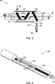
- 8080
- Faser-CO2-GasreinheitssensoranordnungFiber CO 2 gas purity sensor assembly
- 8282
- zentraler Faserkerncentral fiber core
- 8484
- Längsachselongitudinal axis
- 86, 8886, 88
- periodisch modulierte Brechungsindexgitterperiodically modulated refractive index gratings
- 9090
- Faserhüllefiber cladding
- 9292
- Anzeigeschichtdisplay layer
- 9494
- Gaskammergas chamber
- 9696
- Gaseinlassgas inlet
- 9898
- Gasauslassgas outlet
- 100100
- thermische Stabilisatorenthermal stabilizers
- 102102
- VentilValve
- 104104
- Strömungsmesserflowmeter
- 106106
- zickzackförmiger Gasströmungspfadzigzag gas flow path
- 120120
- Faser-Gasanzeige(FGS)-AnordnungFiber gas indicator (FGS) assembly
- 121121
- Faser-GassensoranordnungenFiber gas sensor arrays
- 122122
- FasergitterstrukturenFiber grating structures
- 124124
- apodisierte Fasergitterstrukturenapodized fiber lattice structures
- 126126
- V-RilleV-groove
- 128128
- Faserhüllefiber cladding
- 130130
- Diagramm einer FGS-Wellenlängenverschiebung als eine Funktion der TemperaturDiagram of a FGS wavelength shift as a function of temperature
- 132132
- FGS-SpitzenpositionFGS top position
- 140140
- Diagramm einer Variation der Wellenlängenverschiebung mit Bezug auf die TemperaturDiagram of a variation of the wavelength shift with respect to the temperature
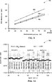
- 150150
- Diagramm einer Reaktion des Faser-CO2-Gassensors zur CO2-ReinheitsmessungDiagram of a reaction of the fiber CO 2 gas sensor to CO 2 purity measurement
- 152152
- Reaktion für einen Faser-CO2-Gassensor mit 500 nm Nickel als der AnzeigeschichtReaction for a fiber CO 2 gas sensor with 500 nm nickel as the indicating layer
- 154154
- Reaktion für einen Faser-CO2-Gassensor mit 100 nm Nickel als der AnzeigeschichtReaction for a fiber CO 2 gas sensor with 100 nm nickel as the indicating layer
- 170170
- Diagramm einer Reaktion eines Faser-CO2-Gasreinheitssensors für einen vollen Bereich von Messungen von mit Luft vermischtem CO2-GasDiagram of a response of a fiber CO 2 gas purity sensor for a full range of air-mixed CO 2 gas measurements
- 180180
- Diagramm der CO2-Gasnachweisempfindlichkeit von drei Faser-CO2-Gasreinheitssensoren mit mit N2 vermischtem CO2-GasDiagram of the CO 2 gas detection sensitivity of three fiber CO 2 gas cleanliness sensors with CO 2 gas mixed with N 2
- 182182
- Reaktion für einen Faser-CO2-Gassensor mit 500 nm Nickel als der AnzeigeschichtReaction for a fiber CO 2 gas sensor with 500 nm nickel as the indicating layer
- 184184
- Reaktion für einen Faser-CO2-Gassensor mit 500 nm Aluminium als der AnzeigeschichtReaction for a fiber CO 2 gas sensor with 500 nm aluminum as the indicating layer
- 186186
- Reaktion für einen Faser-CO2-Gassensor mit 500 nm Kupfer als der AnzeigeschichtReaction for a fiber CO 2 gas sensor with 500 nm copper as the indicating layer
- 190190
- Diagramm einer Reaktion eines Faser-CO2-Gasreinheitssensors zur CO2-ReinheitsmessungDiagram of a reaction of a fiber CO 2 gas purity sensor for CO 2 purity measurement
- 220220
- Diagramm der Reaktion eines Faser-Gassensors zur CO2-ReinheitsmessungDiagram of the reaction of a fiber gas sensor to CO 2 purity measurement
- 222222
- Grundliniebaseline
- 240240
- Wiederholbarkeitsreaktion eines Faser-CO2-Gassensors für ein mit Luft vermischtes CO2-GasRepeatability reaction of a fiber CO 2 gas sensor for an air-mixed CO 2 gas
- 260260
- Reaktion der Amplitude eines Faser-CO2-Gassensors als eine Funktion der GasströmungsrateResponse of the amplitude of a fiber CO 2 gas sensor as a function of gas flow rate
Claims (10)
Applications Claiming Priority (2)
| Application Number | Priority Date | Filing Date | Title |
|---|---|---|---|
| US12/845,871 | 2010-07-29 | ||
| US12/845,871 US8467977B2 (en) | 2010-07-29 | 2010-07-29 | Fiber optic carbon dioxide purity sensor package and system |
Publications (1)
| Publication Number | Publication Date |
|---|---|
| DE102011052233A1 true DE102011052233A1 (en) | 2012-02-02 |
Family
ID=44586744
Family Applications (1)
| Application Number | Title | Priority Date | Filing Date |
|---|---|---|---|
| DE102011052233A Withdrawn DE102011052233A1 (en) | 2010-07-29 | 2011-07-28 | Fiberoptic carbon dioxide purity sensor assembly and system |
Country Status (5)
| Country | Link |
|---|---|
| US (1) | US8467977B2 (en) |
| JP (1) | JP2012032398A (en) |
| KR (1) | KR20120012426A (en) |
| DE (1) | DE102011052233A1 (en) |
| GB (1) | GB2488613B (en) |
Families Citing this family (21)
| Publication number | Priority date | Publication date | Assignee | Title |
|---|---|---|---|---|
| US8768112B2 (en) | 2010-10-22 | 2014-07-01 | General Electric Company | System having fiber optic purity sensor |
| US8542955B2 (en) * | 2010-10-28 | 2013-09-24 | General Electric Company | Gas detection system incorporating fiber gas sensors having fiber bragg gratings |
| CN103107842B (en) * | 2012-09-05 | 2015-11-25 | 华为技术有限公司 | Optical splitter port identification system |
| CN105580487B (en) | 2013-09-25 | 2019-04-26 | 索尼公司 | Remote communication devices and method |
| EP3036940B1 (en) | 2013-09-25 | 2018-02-28 | Sony Corporation | Telecommunications apparatus and methods |
| EP3063894B1 (en) | 2013-10-31 | 2020-04-15 | Sony Corporation | Transmission of measurement reports in a wireless communication system |
| US9453807B2 (en) * | 2014-04-08 | 2016-09-27 | Ams International Ag | Thermal conductivity gas sensor with amplification material |
| WO2016120056A1 (en) | 2015-01-30 | 2016-08-04 | Sony Corporation | Telecommunications apparatus and methods |
| US10484888B2 (en) | 2015-02-12 | 2019-11-19 | Sony Corporation | Telecommunications apparatus and methods |
| EP3278612B1 (en) | 2015-03-31 | 2019-05-08 | Sony Corporation | Telecommunications apparatus and method |
| CN106770738B (en) * | 2016-12-03 | 2024-02-20 | 浙江大学 | Expired gas multicomponent detector with corrected carbon dioxide concentration and detection method |
| US10767878B2 (en) | 2017-11-21 | 2020-09-08 | Emerson Climate Technologies, Inc. | Humidifier control systems and methods |
| WO2019204792A1 (en) | 2018-04-20 | 2019-10-24 | Emerson Climate Technologies, Inc. | Coordinated control of standalone and building indoor air quality devices and systems |
| US11226128B2 (en) | 2018-04-20 | 2022-01-18 | Emerson Climate Technologies, Inc. | Indoor air quality and occupant monitoring systems and methods |
| US11371726B2 (en) | 2018-04-20 | 2022-06-28 | Emerson Climate Technologies, Inc. | Particulate-matter-size-based fan control system |
| US11486593B2 (en) | 2018-04-20 | 2022-11-01 | Emerson Climate Technologies, Inc. | Systems and methods with variable mitigation thresholds |
| WO2019204790A1 (en) | 2018-04-20 | 2019-10-24 | Emerson Climate Technologies, Inc. | Systems and methods with variable mitigation thresholds |
| WO2019217499A1 (en) * | 2018-05-11 | 2019-11-14 | Carrier Corporation | Screening apparatus comprising a wavelength-shifting element, and corresponding method |
| US11567025B2 (en) * | 2018-08-10 | 2023-01-31 | Tdk Corporation | Gas sensor |
| CN108838594B (en) * | 2018-08-23 | 2023-10-27 | 北京通为科技有限公司 | Packaging structure of fiber Bragg grating sensor |
| DE102019120699A1 (en) * | 2019-07-31 | 2021-02-04 | Wagner Group Gmbh | Gas measuring device with heating device |
Family Cites Families (12)
| Publication number | Priority date | Publication date | Assignee | Title |
|---|---|---|---|---|
| US5714121A (en) | 1995-09-28 | 1998-02-03 | Optical Sensors Incorporated | Optical carbon dioxide sensor, and associated methods of manufacture |
| DE19900019B4 (en) | 1999-01-02 | 2004-12-02 | Robert Bosch Gmbh | Fiber optic sensor |
| US6989246B2 (en) | 2002-01-10 | 2006-01-24 | Becton, Dickinson And Company | Sensor formulation for simultaneously monitoring at least two components of a gas composition |
| CA2372637A1 (en) | 2002-02-20 | 2003-08-20 | Institut National D'optique | Packaged optical sensors on the side of optical fibres |
| US20070048181A1 (en) | 2002-09-05 | 2007-03-01 | Chang Daniel M | Carbon dioxide nanosensor, and respiratory CO2 monitors |
| US7421162B2 (en) * | 2005-03-22 | 2008-09-02 | General Electric Company | Fiber optic sensing device and method of making and operating the same |
| US7151872B1 (en) | 2005-11-22 | 2006-12-19 | General Electric Company | Method, system and module for monitoring a power generating system |
| US20070243624A1 (en) | 2006-04-12 | 2007-10-18 | Proton Energy Systems Inc. | Hydrogen emission reporting system and method thereof |
| WO2008136870A2 (en) | 2006-12-18 | 2008-11-13 | University Of Pittsburgh - Of The Commonwealth System Of Higher Education | Fiber optic gas sensor |
| US7489835B1 (en) * | 2008-03-28 | 2009-02-10 | General Electric Company | Sensing system with fiber gas sensor |
| EP2202548A1 (en) | 2008-12-23 | 2010-06-30 | Nederlandse Organisatie voor Toegepast-Natuurwetenschappelijk Onderzoek TNO | Distributed optical chemical sensor |
| US8547553B2 (en) | 2010-03-17 | 2013-10-01 | General Electric Company | Fiber optic hydrogen purity sensor and system |
-
2010
- 2010-07-29 US US12/845,871 patent/US8467977B2/en active Active
-
2011
- 2011-07-18 GB GB1112281.9A patent/GB2488613B/en not_active Expired - Fee Related
- 2011-07-27 JP JP2011163776A patent/JP2012032398A/en active Pending
- 2011-07-28 KR KR1020110075123A patent/KR20120012426A/en not_active Application Discontinuation
- 2011-07-28 DE DE102011052233A patent/DE102011052233A1/en not_active Withdrawn
Also Published As
| Publication number | Publication date |
|---|---|
| JP2012032398A (en) | 2012-02-16 |
| US20120029835A1 (en) | 2012-02-02 |
| GB201112281D0 (en) | 2011-08-31 |
| GB2488613A (en) | 2012-09-05 |
| KR20120012426A (en) | 2012-02-09 |
| US8467977B2 (en) | 2013-06-18 |
| GB2488613B (en) | 2014-07-30 |
Similar Documents
| Publication | Publication Date | Title |
|---|---|---|
| DE102011052233A1 (en) | Fiberoptic carbon dioxide purity sensor assembly and system | |
| Aldhafeeri et al. | A review of methane gas detection sensors: Recent developments and future perspectives | |
| US10718711B1 (en) | Fiber optic sensing apparatus, system, and method of use thereof | |
| DE102011001190A1 (en) | Fiber optic hydrogen purge sensor and system | |
| Liu et al. | High sensitivity optical fiber sensors for simultaneous measurement of methanol and ethanol | |
| Caucheteur et al. | Hybrid fiber gratings coated with a catalytic sensitive layer for hydrogen sensing in air | |
| Rifat et al. | Development of photonic crystal fiber-based gas/chemical sensors | |
| DE102009003677A1 (en) | Measuring system with fiber-gas sensor | |
| Vitoria et al. | Fiber optic gas sensors based on lossy mode resonances and sensing materials used therefor: A comprehensive review | |
| Yang et al. | Optical fiber sensor based on a cholesteric liquid crystal film for mixed VOC sensing | |
| Mallik et al. | Whispering gallery mode micro resonators for multi-parameter sensing applications | |
| DE102004011731A1 (en) | Robust palladium-based hydrogen sensors | |
| Chen et al. | Ultra-fast hygrometer based on U-shaped optical microfiber with nanoporous polyelectrolyte coating | |
| US9019502B1 (en) | Electronically conductive perovskite-based oxide nanoparticles and films for optical sensing applications | |
| CN110726697A (en) | Mach-Zehnder interferometer optical fiber ammonia gas sensor based on tapered fine core optical fiber | |
| Deng et al. | Trace hydrogen sulfide gas sensor based on tungsten sulfide membrane-coated thin-core fiber modal interferometer | |
| Poole et al. | Potential to detect hydrogen concentration gradients with palladium infused mesoporous-titania on D-shaped optical fiber | |
| Wang et al. | Highly sensitive PCF-SPR biosensor for hyperthermia temperature monitoring | |
| US9568377B1 (en) | Nanocomposite thin films for optical temperature sensing | |
| Lee et al. | Simultaneous temperature and strain sensing with hybrid resonator of fiber Bragg grating and whispering gallery resonator | |
| Rong et al. | Delafossite AgAlO 2 modified long-period grating for highly-sensitive ammonia sensor | |
| Rodriguez-Rodriguez et al. | Polymer optical fiber moisture sensor based on evanescent-wave scattering to measure humidity in oil-paper insulation in electrical apparatus | |
| Silva et al. | Optical fiber sensing system based on long-period gratings for remote refractive index measurement in aqueous environments | |
| Tong et al. | Research on repeatability and stability of sensors based on alcohol-filled photonic crystal fiber | |
| Wang et al. | Humidity characteristics of a weak fiber Bragg grating array coated with polyimide |
Legal Events
| Date | Code | Title | Description |
|---|---|---|---|
| R119 | Application deemed withdrawn, or ip right lapsed, due to non-payment of renewal fee |