DE102010064278A1 - Method for density correction in vortex flow meter - Google Patents
Method for density correction in vortex flow meter Download PDFInfo
- Publication number
- DE102010064278A1 DE102010064278A1 DE102010064278A DE102010064278A DE102010064278A1 DE 102010064278 A1 DE102010064278 A1 DE 102010064278A1 DE 102010064278 A DE102010064278 A DE 102010064278A DE 102010064278 A DE102010064278 A DE 102010064278A DE 102010064278 A1 DE102010064278 A1 DE 102010064278A1
- Authority
- DE
- Germany
- Prior art keywords
- section
- medium
- region
- measuring cross
- measuring
- Prior art date
- Legal status (The legal status is an assumption and is not a legal conclusion. Google has not performed a legal analysis and makes no representation as to the accuracy of the status listed.)
- Withdrawn
Links
Images
Classifications
-
- G—PHYSICS
- G01—MEASURING; TESTING
- G01F—MEASURING VOLUME, VOLUME FLOW, MASS FLOW OR LIQUID LEVEL; METERING BY VOLUME
- G01F1/00—Measuring the volume flow or mass flow of fluid or fluent solid material wherein the fluid passes through a meter in a continuous flow
- G01F1/05—Measuring the volume flow or mass flow of fluid or fluent solid material wherein the fluid passes through a meter in a continuous flow by using mechanical effects
- G01F1/20—Measuring the volume flow or mass flow of fluid or fluent solid material wherein the fluid passes through a meter in a continuous flow by using mechanical effects by detection of dynamic effects of the flow
- G01F1/32—Measuring the volume flow or mass flow of fluid or fluent solid material wherein the fluid passes through a meter in a continuous flow by using mechanical effects by detection of dynamic effects of the flow using swirl flowmeters
- G01F1/3209—Measuring the volume flow or mass flow of fluid or fluent solid material wherein the fluid passes through a meter in a continuous flow by using mechanical effects by detection of dynamic effects of the flow using swirl flowmeters using Karman vortices
-
- G—PHYSICS
- G01—MEASURING; TESTING
- G01F—MEASURING VOLUME, VOLUME FLOW, MASS FLOW OR LIQUID LEVEL; METERING BY VOLUME
- G01F1/00—Measuring the volume flow or mass flow of fluid or fluent solid material wherein the fluid passes through a meter in a continuous flow
- G01F1/74—Devices for measuring flow of a fluid or flow of a fluent solid material in suspension in another fluid
-
- G—PHYSICS
- G01—MEASURING; TESTING
- G01F—MEASURING VOLUME, VOLUME FLOW, MASS FLOW OR LIQUID LEVEL; METERING BY VOLUME
- G01F1/00—Measuring the volume flow or mass flow of fluid or fluent solid material wherein the fluid passes through a meter in a continuous flow
- G01F1/76—Devices for measuring mass flow of a fluid or a fluent solid material
- G01F1/86—Indirect mass flowmeters, e.g. measuring volume flow and density, temperature or pressure
-
- G—PHYSICS
- G01—MEASURING; TESTING
- G01F—MEASURING VOLUME, VOLUME FLOW, MASS FLOW OR LIQUID LEVEL; METERING BY VOLUME
- G01F15/00—Details of, or accessories for, apparatus of groups G01F1/00 - G01F13/00 insofar as such details or appliances are not adapted to particular types of such apparatus
- G01F15/02—Compensating or correcting for variations in pressure, density or temperature
- G01F15/022—Compensating or correcting for variations in pressure, density or temperature using electrical means
- G01F15/024—Compensating or correcting for variations in pressure, density or temperature using electrical means involving digital counting
-
- G—PHYSICS
- G01—MEASURING; TESTING
- G01F—MEASURING VOLUME, VOLUME FLOW, MASS FLOW OR LIQUID LEVEL; METERING BY VOLUME
- G01F25/00—Testing or calibration of apparatus for measuring volume, volume flow or liquid level or for metering by volume
- G01F25/10—Testing or calibration of apparatus for measuring volume, volume flow or liquid level or for metering by volume of flowmeters
Landscapes
- Physics & Mathematics (AREA)
- Fluid Mechanics (AREA)
- General Physics & Mathematics (AREA)
- Measuring Volume Flow (AREA)
- Investigating Or Analyzing Materials By The Use Of Magnetic Means (AREA)
Abstract
Es wird ein Verfahren zum Bestimmen eines Massedurchflusses eines, zumindest zeitweise mindestens zweiphasigen Mediums durch ein Messrohr (4) eines Wirbelströmungsmessgerätes (2) bereitgestellt. Dabei weist das Messrohr (4) in einem Messquerschnitt mindestens einen Staukörper (8) zur Erzeugung von Wirbeln auf und durch sensorische Erfassung der erzeugten Wirbel wird eine Strömungsgeschwindigkeit des Mediums im Bereich des Messquerschnitts bestimmt. Bei dem Verfahren wird die Dichte des Mediums im Bereich des Messquerschnitts aus der spezifischen, totalen Enthalpie des Mediums im Bereich des Messquerschnitts, aus der Strömungsgeschwindigkeit des Mediums im Bereich des Messquerschnitts, aus einem statischen Druck des Mediums im Bereich des Messquerschnitts und aus der statischen Temperatur des Mediums im Bereich des Messquerschnitts bestimmt. Ferner wird der Massedurchfluss aus der bestimmten Strömungsgeschwindigkeit, der bestimmten Dichte und einem Strömungsquerschnitt des Mediums im Bereich des Messquerschnitts bestimmt.A method is provided for determining a mass flow of a, at least temporarily at least two-phase, medium through a measuring tube (4) of a vortex flow measuring device (2). The measuring tube (4) has at least one bluff body (8) for generating vortices in a measuring cross-section, and a flow velocity of the medium in the area of the measuring cross-section is determined by sensing the generated vortices. In the method, the density of the medium in the area of the measurement cross-section is determined from the specific, total enthalpy of the medium in the area of the measurement cross-section, from the flow velocity of the medium in the area of the measurement cross-section, from a static pressure of the medium in the area of the measurement cross-section and from the static temperature of the medium in the area of the measurement cross section. Furthermore, the mass flow is determined from the determined flow velocity, the determined density and a flow cross-section of the medium in the area of the measurement cross-section.
Description
Die vorliegende Erfindung betrifft ein Verfahren zum Bestimmen eines Massedurchflusses eines, zumindest zeitweise mindestens zweiphasigen Mediums durch ein Messrohr eines Wirbelströmungsmessgerätes, wobei das Messrohr in einem Messquerschnitt mindestens einen Staukörper zur Erzeugung von Wirbeln aufweist und wobei durch sensorische Erfassung der erzeugten Wirbel eine Strömungsgeschwindigkeit des Mediums im Bereich des Messquerschnitts bestimmt wird sowie ein entsprechend ausgebildetes Wirbelströmungsmessgerät.The present invention relates to a method for determining a mass flow of an at least temporarily at least two-phase medium through a measuring tube of a vortex flow meter, wherein the measuring tube in a measuring cross section at least one bluff body for generating vortices and wherein by sensory detection of the generated vortex a flow velocity of the medium in Area of the measuring cross section is determined and a correspondingly formed vortex flow meter.
Für die Durchflussmessung von strömungsfähigen Medien (z. B. Fluiden) in Rohrleitungen, insbesondere von Gasströmungen oder Dampfströmungen im Hochtemperaturbereich, werden häufig Wirbelströmungsmessgeräte eingesetzt. Bei derartigen Wirbelströmungsmessgeräten wird ein Staukörper, der ein Strömungshindernis für das strömende Medium bildet, derart in dem Strömungspfad angeordnet, dass das jeweilige Medium beidseitig des Strömungshindernisses vorbeiströmen kann. Dabei lösen sich an dem Strömungshindernis zu beiden Seiten hin Wirbel ab. Über einen weiten Reynoldszahlbereich lösen sich die Wirbel dabei alternierend an den beiden Seiten des Strömungshindernisses ab, so dass eine gestaffelte Anordnung der Wirbel entsteht. Diese gestaffelte Anordnung der Wirbel wird als Kármán'sche Wirbelstraße bezeichnet. Bei Wirbelströmungsmessgeräten wird dabei das Prinzip ausgenutzt, dass die Wirbelablösefrequenz, mit der diese Wirbel gebildet werden, über einen weiten Reynoldszahlbereich proportional zur Strömungsgeschwindigkeit bzw. zum Volumendurchfluss des jeweiligen Mediums ist. Die erzeugten Wirbel werden in dem Wirbelströmungsmessgerät sensorisch erfasst. Dementsprechend kann aus der erfassten Wirbelablösefrequenz der Wirbel, die im Folgenden als Vortexfrequenz bezeichnet wird, und einen, für den jeweiligen Typ von Wirbelströmungsmessgerät charakteristischen Kalibrierfaktor die Strömungsgeschwindigkeit bzw. der Volumendurchfluss bestimmt werden.For the flow measurement of fluid media (eg fluids) in pipelines, in particular gas flows or vapor flows in the high temperature range, vortex flow meters are often used. In such turbulence flow measuring devices, a bluff body, which forms a flow obstacle for the flowing medium, is arranged in the flow path in such a way that the respective medium can flow past on both sides of the flow obstacle. At the flow obstacle, vortices are released on both sides. Over a wide Reynolds number range, the vortices alternate alternately on the two sides of the flow obstacle, resulting in a staggered arrangement of the vortices. This staggered arrangement of vortices is referred to as Kármán vortex street. In vortex flowmeters, the principle is exploited here that the vortex shedding frequency, with which these vortexes are formed, is proportional to the flow velocity or to the volume flow of the respective medium over a wide Reynolds number range. The generated vortices are sensed in the vortex flow meter. Accordingly, from the detected vortex shedding frequency, the vortex, hereinafter referred to as vortex frequency, and a calibration factor characteristic of each type of vortex flow meter, can be determined as the flow velocity and the volume flow, respectively.
Liegen innerhalb der Rohrleitung Prozessbedingungen im Bereich eines Phasenübergangs des strömenden Mediums oder eines in dem Medium enthaltenen Stoffes vor, so kann bei einem Teil des Mediums ein Phasenübergang stattfinden. Das Medium liegt dann in zwei oder mehreren Phasen vor. Insbesondere kann ein Teil eines gasförmigen Mediums auskondensieren. Bei der Bestimmung des Volumendurchflusses oder des Massedurchflusses durch ein Wirbelströmungsmessgerät besteht dabei das Problem, dass dieses innerhalb des Messrohres im Bereich des Staukörpers (Messquerschnitt) einen reduzierten Strömungsquerschnitt verglichen mit einem stromaufwärtigen und einem stromabwärtigen Abschnitt des Messrohres aufweist. Dadurch ist die Strömungsgeschwindigkeit des Mediums im Bereich des Messquerschnitts lokal erhöht. Bei inkompressiblen Medien kann dieser Effekt relativ einfach in einen Kalibrierfaktor mit eingerechnet werden, durch den das (durch das Verhältnis der Strömungsquerschnitte vorgegebene und feste) Verhältnis zwischen der Strömungsgeschwindigkeit im Bereich des Messquerschnitts und der Strömungsgeschwindigkeit in einem stromaufwärts oder stromabwärts des Messquerschnitts gelegenen Rohrleitungsabschnitt (nachfolgend: Anschlussrohr) berücksichtigt wird. Bei kompressiblen Medien, wie beispielsweise bei Gasen, ist dieses Verhältnis jedoch nicht fest. Beispielsweise treten bei gasförmigen Medien im Bereich des Messquerschnitts ein erheblicher Temperaturabfall und ein Druckabfall auf. Die Dichte des Mediums unterscheidet sich im Bereich des Messquerschnitts erheblich von der Dichte im Anschlussrohrbereich. Zusätzlich kann der Fall auftreten, dass aufgrund der unterschiedlichen Prozessbedingungen im Bereich des Messquerschnitts ein Teil des Mediums auskondensiert, während er im Anschlussrohrbereich wieder verdampft, was zu einer erheblichen Abweichung der Dichte des Mediums im Bereich des Messquerschnitts von der Dichte des Mediums im Anschlussrohrbereich führt. Allgemein kann die Problematik auftreten, dass aufgrund der, im Bereich des Messquerschnitts vorliegenden Prozessbedingungen bei einem Teil des Mediums ein Phasenübergang auftritt, der nachfolgend im Anschlussrohrbereich wieder in umgekehrter Richtung abläuft. Wird ausgehend von der lokal im Bereich des Messquerschnitts gemessenen Strömungsgeschwindigkeit (alternativ: von dem lokal im Bereich des Messquerschnitts gemessenen Volumendurchfluss) mit einem konstanten Kalibrierfaktor, der spezifisch für den jeweiligen Typ von Wirbelströmungsmessgerät ist, die Strömungsgeschwindigkeit im Anschlussrohrbereich berechnet, so tritt aufgrund der oberhalb erläuterten Effekte ein Fehler auf. Diese Problematik besteht insbesondere dann, wenn im Bereich des Messquerschnitts aufgrund der lokal im Bereich des Messquerschnitts auftretenden Prozessbedingungen ein Phasenübergang von einem Teil des Mediums auftritt.If process conditions in the region of a phase transition of the flowing medium or of a substance contained in the medium are present within the pipeline, a phase transition may take place in a part of the medium. The medium is then present in two or more phases. In particular, a part of a gaseous medium can condense out. When determining the volume flow or the mass flow through a vortex flow meter, there is the problem that this has a reduced flow cross section within the measuring tube in the region of the bluff body (measuring cross section) compared with an upstream and a downstream portion of the measuring tube. As a result, the flow velocity of the medium is locally increased in the region of the measuring cross section. In the case of incompressible media, this effect can relatively easily be included in a calibration factor by which the ratio between the flow velocity in the region of the measuring cross section and the flow velocity (defined by the ratio of the flow cross sections) and the flow velocity in a pipeline section located upstream or downstream of the measuring cross section (hereafter : Connecting pipe) is taken into account. For compressible media, such as gases, this ratio is not fixed. For example, occur in gaseous media in the region of the measuring cross section, a significant temperature drop and a pressure drop. The density of the medium differs considerably in the area of the measuring cross-section from the density in the connecting pipe area. In addition, it may be the case that due to the different process conditions in the region of the measuring cross section, part of the medium condenses out, while it evaporates again in the connecting pipe region, which leads to a considerable deviation of the density of the medium in the region of the measuring cross section from the density of the medium in the connecting pipe region. In general, the problem may arise that, due to the process conditions present in the region of the measuring cross section, a phase transition occurs for a part of the medium, which subsequently proceeds again in the opposite direction in the connecting pipe region. If the flow velocity in the connection pipe area is calculated on the basis of the flow velocity measured locally in the area of the measuring cross section (alternatively: from the volume flow measured locally in the area of the measuring cross section) with a constant calibration factor which is specific to the respective type of vortex flow meter, then explained effects an error. This problem exists, in particular, when a phase transition of a part of the medium occurs in the region of the measuring cross section due to the process conditions occurring locally in the region of the measuring cross section.
Dementsprechend besteht die Aufgabe der vorliegenden Erfindung darin, ein Verfahren zur Bestimmung eines Durchflussmesswertes sowie ein entsprechend ausgebildetes Wirbelströmungsmessgerät bereitzustellen, bei dem das Auftreten eines Messfehlers aufgrund eines lokal, im Bereich des Messquerschnitts auftretenden Phasenübergangs eines Teils des Mediums vermieden wird.Accordingly, the object of the present invention is to provide a method for determining a flow measurement value and a correspondingly embodied vortex flow meter, in which the occurrence of a measurement error due to a locally occurring in the region of the measuring cross section phase transition of a portion of the medium is avoided.
Die Aufgabe wird durch ein Verfahren gemäß Anspruch 1 sowie durch ein Wirbelströmungsmessgerät gemäß Anspruch 13 gelöst. Vorteilhafte Weiterbildungen der Erfindung sind in den Unteransprüchen angegeben. The object is achieved by a method according to
Gemäß der vorliegenden Erfindung wird ein Verfahren zum Bestimmen eines Massedurchflusses eines, zumindest zeitweise mindestens zweiphasigen Mediums durch ein Messrohr eines Wirbelströmungsmessgerätes bereitgestellt. Dabei weist das Messrohr in einem Messquerschnitt mindestens einen Staukörper zur Erzeugung von Wirbeln auf und durch sensorische Erfassung der erzeugten Wirbel wird eine Strömungsgeschwindigkeit des Mediums im Bereich des Messquerschnitts bestimmt. Das Verfahren weist dabei nachfolgende Schritte auf:
- A) Bestimmen der Dichte des Mediums im Bereich des Messquerschnitts aus der spezifischen, totalen Enthalpie des Mediums im Bereich des Messquerschnitts, aus der Strömungsgeschwindigkeit des Mediums im Bereich des Messquerschnitts, aus einem statischen Druck des Mediums im Bereich des Messquerschnitts und aus einer statischen Temperatur des Mediums im Bereich des Messquerschnitts; und
- B) Bestimmen des Massedurchflusses aus der bestimmten Strömungsgeschwindigkeit, der bestimmten Dichte und einem Strömungsquerschnitt des Mediums im Bereich des Messquerschnitts.
- Determining the density of the medium in the region of the measuring cross section from the specific, total enthalpy of the medium in the region of the measuring cross section, from the flow velocity of the medium in the region of the measuring cross section, from a static pressure of the medium in the region of the measuring cross section and from a static temperature of the medium Medium in the region of the measuring cross section; and
- B) Determining the mass flow from the determined flow velocity, the specific density and a flow cross section of the medium in the region of the measuring cross section.
Indem gemäß der vorliegenden Erfindung die Dichte des Mediums im Bereich des Messquerschnitts bestimmt wird, kann aus dieser zusammen mit der Strömungsgeschwindigkeit im Bereich des Messquerschnitts (die durch das Wirbelströmungsmessgerät lokal im Bereich des Messquerschnitts erfasst wird) und dem Strömungsquerschnitt des Mediums im Bereich des Messquerschnitts (der aufgrund der Geräteabmessungen bekannt ist), der korrekte Massedurchfluss des Mediums berechnet werden. Da der Massenstrom entlang der Medium-führenden Rohrleitung konstant ist, bildet der so ermittelte Massedurchfluss auch einen korrekten Wert für den Anschlussrohrbereich. Indem bei dem Schritt des Bestimmens der Dichte (Schritt A)) die spezifische, totale Enthalpie des Mediums im Bereich des Messquerschnitts, die Strömungsgeschwindigkeit des Mediums im Bereich des Messquerschnitts, der statische Druck des Mediums im Bereich des Messquerschnitts und die statische Temperatur des Mediums im Bereich des Messquerschnitts eingehen, wird berücksichtigt, dass gegebenenfalls bei einem Teil des Mediums ein Phasenübergang stattgefunden hat. Ein Messfehler des bestimmten Massedurchflusses, der dadurch bedingt ist, dass lokal im Bereich des Messquerschnitts ein Phasenübergang eines Teils des Mediums stattfindet, wird somit vermieden.By determining the density of the medium in the region of the measuring cross section according to the present invention, this can be determined together with the flow velocity in the region of the measuring cross section (which is detected locally by the vortex flow meter in the region of the measuring cross section) and the flow cross section of the medium in the region of the measuring cross section (FIG. which is known due to the device dimensions), the correct mass flow of the medium can be calculated. Since the mass flow along the medium-carrying pipeline is constant, the mass flow determined in this way also forms a correct value for the connection pipe area. In the step of determining the density (step A)), the specific, total enthalpy of the medium in the region of the measuring cross section, the flow velocity of the medium in the region of the measuring cross section, the static pressure of the medium in the region of the measuring cross section and the static temperature of the medium in In the area of the measuring cross-section, it is considered that, if necessary, a phase transition has taken place in a part of the medium. A measurement error of the specific mass flow, which is due to the fact that a phase transition of a portion of the medium takes place locally in the region of the measuring cross section, is thus avoided.
Bei dem erfindungsgemäßen Verfahren (und entsprechend auch bei dem nachfolgend erläuterten, erfindungsgemäßen Wirbelströmungsmessgerät) kann jeweils die (in dem jeweiligen Anspruch) angegebene, physikalische Größe selbst bestimmt werden oder alternativ eine, für diese Größe charakteristische, alternative, physikalische Größe, aus der aufgrund allgemein bekannter, physikalischer Zusammenhänge die jeweils angegebene, pyhsikalische Größe erhältlich ist. Dieser Grundsatz gilt ins besondere für die Bestimmung der Strömungsgeschwindigkeit, der Dichte (vgl. Schritt A)) und des Massedurchflusses (vgl. Schritt B)). Eine für die Strömungsgeschwindigkeit alternative, physikalische Größe ist beispielsweise der Volumendurchfluss. Auch bei den jeweils angegebenen, physikalischen Größen, die für die Bestimmung (vgl. z. B. Schritte A) und B)) herangezogen werden, kann jeweils die (im jeweiligen Anspruch) angegebene, physikalische Größe herangezogen werden oder alternativ eine andere, physikalische Größe, bei der aufgrund allgemein bekannter, physikalischer Zusammenhänge bekannt ist, dass diese entsprechend für die Bestimmung herangezogen werden kann. Dieser Grundsatz gilt insbesondere für die Dichte, die spezifische, totale Enthalpie, die Strömungsgeschwindigkeit, den statischen Druck und die statische Temperatur bei der Bestimmung der Dichte (vgl. Schritt A)) sowie für die Strömungsgeschwindigkeit, die Dichte und den Strömungsquerschnitt bei der Bestimmung des Massedurchflusses (vgl. Schritt B)). Diese Grundsätze gelten entsprechend auch bei den nachfolgend erläuterten Bestimmungen von physikalischen Größen (z. B. in Bezug auf Weiterbildungen), ohne dass hierauf jedesmal explizit hingewiesen wird.In the method according to the invention (and correspondingly also in the vortex flowmeter according to the invention explained below), the physical variable (specified in the respective claim) can itself be determined or, alternatively, an alternative, physical variable characteristic of this variable, on the basis of which known, physical relationships, the specified in each case, physical size is available. This principle applies in particular to the determination of the flow velocity, the density (see step A)) and the mass flow rate (see step B)). An alternative physical variable for the flow velocity is, for example, the volume flow. The physical quantities specified in the respective claim can also be used for the particular physical quantities specified for the determination (cf., for example, steps A) and B)) or, alternatively, another physical property Size at which it is known on the basis of generally known physical relationships that it can be used accordingly for the determination. This principle applies in particular to the density, the specific total enthalpy, the flow velocity, the static pressure and the static temperature in determining the density (cf step A), as well as the flow velocity, the density and the flow cross section in the determination of the Mass flow (see step B)). These principles also apply accordingly to the determinations of physical quantities explained below (eg with regard to further training), without any explicit mention being made of them.
Wie in dem Fachgebiet allgemein bekannt ist, ergibt die Summe aus dem statischen Druck und dem dynamischen Druck eines strömenden Mediums dessen Totaldruck. Entsprechend ergibt die Summe aus der statischen Temperatur und der dynamischen Temperatur eines strömenden Mediums dessen Totaltemperatur. Dabei sind in dem Fachgebiet entsprechende Sensoren bekannt, durch die der statische Druck und die statische Temperatur eines strömenden Mediums, insbesondere des strömenden Mediums im Bereich des Messquerschnitts, erfassbar sind.As is well known in the art, the sum of the static pressure and the dynamic pressure of a flowing medium gives its total pressure. Accordingly, the sum of the static temperature and the dynamic temperature of a flowing medium gives its total temperature. In this case, corresponding sensors are known in the field, by means of which the static pressure and the static temperature of a flowing medium, in particular of the flowing medium in the region of the measuring cross section, can be detected.
Als Medium wird allgemein ein strömungsfähiges Medium bezeichnet, das aus einem (einzigen) Stoff (z. B. H2O) oder einem Stoffgemisch (z. B. Luft enthaltend Wasserdampf) gebildet sein kann. Das Medium liegt insbesondere in einer gasförmigen Phase vor, wobei ein Teil desselben zeitweise oder dauerhaft in einer zweiten Phase (flüssig oder fest) vorliegt. Dabei können die erste und die zweite Phase durch ein und denselben Stoff gebildet werden, der zu einem ersten Anteil in einer ersten Phase (bzw. Aggregatszustand) vorliegt und der zu einem zweiten Anteil in einer zweiten Phase (bzw. Aggregatszustand) vorliegt. Setzt sich das Medium aus mehreren Stoffen (z. B. unterschiedliche Gase, insbesondere Luft enthaltend Wasserdampf) zusammen, so kondensiert (d. h. Phasenübergang in flüssige Phase) oder friert (d. h. Phasenübergang in feste Phase) insbesondere nur ein Stoff desselben bei den, in Frage kommenden Prozessbedingungen zumindest teilweise aus. Weiterhin kann das Medium auch noch mindestens eine weitere Phase, wie beispielsweise Feststoffteile (z. B. Sand oder Staub) mitführen, bei der bei den in Frage kommenden Prozessbedingungen jedoch kein Phasenübergang stattfindet. Das Medium kann also auch mehr als nur zwei Phasen aufweisen.A medium is generally referred to as a flowable medium, which may be formed from a (single) substance (eg H 2 O) or a mixture of substances (eg air containing water vapor). The medium is present in particular in a gaseous phase, part of which is present temporarily or permanently in a second phase (liquid or solid). In this case, the first and the second phase by one and the same Substance are formed, which is present in a first portion in a first phase (or state of aggregation) and which is present in a second portion in a second phase (or state of aggregation). If the medium is composed of several substances (eg different gases, in particular air containing water vapor), then condenses (ie phase transition into liquid phase) or freezes (ie phase transition into solid phase) in particular only one substance of the same in the, in question coming process conditions at least partially. Furthermore, the medium may also carry at least one further phase, such as, for example, solid particles (eg sand or dust), in which, however, no phase transition takes place under the process conditions in question. The medium can therefore also have more than just two phases.
Das Messrohr, in welchem der Staukörper angeordnet ist, bildet insbesondere einen Teil des Wirbelströmungsmessgerätes und wird in eine, das strömende Medium führende Rohrleitung eingesetzt. Alternativ kann es auch einen integralen Bestandteil der jeweiligen Rohrleitung bilden. Die, durch den Staukörper erzeugten Wirbel in dem strömenden Medium bilden insbesondere Kármán'sche Wirbel, die durch mindestens einen entsprechenden Wirbelsensor des Wirbelströmungsmessgerätes erfassbar sind. Der Stauköper weist insbesondere mindestens zwei derart ausgebildete Abrisskanten auf, dass sich an diesen im Einsatz Kármán'sche Wirbel ablösen. Die spezifische, totale Enthalpie wird insbesondere durch die Summe der spezifischen Enthalpie und der spezifischen, kinetischen Energie des Mediums gebildet.The measuring tube, in which the bluff body is arranged, in particular forms part of the vortex flow meter and is inserted into a, the flowing medium leading pipeline. Alternatively, it may also form an integral part of the respective pipeline. The vortices generated by the bluff body in the flowing medium in particular form Karman vortices, which can be detected by at least one corresponding vortex sensor of the vortex flow meter. In particular, the storage enclosure has at least two tear-off edges formed in such a way that detach Kármán's vortexes during use. The specific, total enthalpy is formed in particular by the sum of the specific enthalpy and the specific kinetic energy of the medium.
Gemäß einer Weiterbildung werden die Schritte des Bestimmens der Strömungsgeschwindigkeit, des Bestimmens der Dichte (vgl. Schritt A)) und des Bestimmens des Massedurchflusses (vgl. Schritt B)) in dem Wirbelströmungsmessgerät durchgeführt. Insbesondere werden die, durch den Staukörper erzeugten Wirbel sensorisch (durch mindestens einen, entsprechend ausgebildeten Sensor) erfasst und die nachfolgenden Schritte des Bestimmens durch eine entsprechend ausgebildete Elektronik des Wirbelströmungsmessgerätes durchgeführt. Die Elektronik kann dabei digital und/oder analog ausgebildet sein, wie es in dem Fachgebiet allgemein bekannt ist.According to a development, the steps of determining the flow velocity, determining the density (see step A)) and determining the mass flow rate (see step B)) are performed in the vortex flow meter. In particular, the eddies generated by the bluff body are detected by sensors (by at least one, correspondingly designed sensor) and the subsequent steps of the determination are carried out by a correspondingly designed electronics of the turbulence meter. The electronics may be digital and / or analog, as is well known in the art.
In der Regel kann die spezifische, totale Enthalpie im Bereich des Messquerschnitts nicht unmittelbar bestimmt werden. Gemäß einer Weiterbildung wird die spezifische, totale Enthalpie des Mediums im Bereich des Messquerschnitts aus dem (statischen) Druck und der (statischen) Temperatur eines Systems bestimmt, dem das strömende Medium entnommen wird und in dem das Medium vor dessen Entnahme ruht. In einem solchen, ruhendem System entsprechen der Totaldruck und die Totaltemperatur jeweils dem statischen Druck und der statischen Temperatur des Mediums. Insbesondere liegt das Medium in diesem System in nur einer Phase, wie beispielsweise gasförmig, vor. Insbesondere wird davon ausgegangen, dass diese spezifische, totale Enthalpie durch das Medium auf dem Weg von dem System bis zu dem Messquerschnitt beibehalten wird. Dabei werden insbesondere die vereinfachenden Annahmen getroffen, dass es sich um eine stationäre Strömung des Mediums handelt und dass zwischen dem System und dem Messquerschnitt keine Wärmequellen existieren, dass kein Wärmestrom zu bzw. von dem Medium weg auftritt, dass keine Reibung auftritt und dass keine Änderung der potentiellen Energie auftritt. Die spezifische, totale Enthalpie entspricht in einem System, in dem das betreffende Medium ruht, der spezifischen Enthalpie. Diese kann anhand bekannter Korrelationen aus dem (statischen bzw. totalen) Druck und der (statischen bzw. totalen) Temperatur des Mediums in dem System bestimmt werden. Setzt sich das Medium aus mehreren Stoffen (Elemente, wie z. B. O2, oder Verbindungen, wie z. B. H2O) mit jeweils bekannten Massenanteilen zusammen, so kann die spezifische, totale Enthalpie jeweils separat für die verschiedenen Stoffe bestimmt werden. Anhand der jeweiligen Massenanteile der verschiedenen Stoffe kann dann die spezifische, totale Enthalpie für das Medium insgesamt bestimmt werden.As a rule, the specific, total enthalpy in the area of the measuring cross-section can not be determined directly. According to a development, the specific, total enthalpy of the medium in the region of the measuring cross section is determined from the (static) pressure and the (static) temperature of a system, from which the flowing medium is taken and in which the medium rests before it is removed. In such a stationary system, the total pressure and the total temperature respectively correspond to the static pressure and the static temperature of the medium. In particular, the medium is present in this system in only one phase, such as gaseous. In particular, it is believed that this specific, total enthalpy is maintained by the medium on its way from the system to the measurement cross section. In particular, the simplifying assumptions are made that it is a stationary flow of the medium and that no heat sources exist between the system and the measuring cross section, that no heat flow to or from the medium occurs, that no friction occurs and that no change the potential energy occurs. The specific, total enthalpy corresponds to the specific enthalpy in a system in which the medium in question rests. This can be determined by known correlations from the (static or total) pressure and the (static or total) temperature of the medium in the system. If the medium is composed of several substances (elements, such as, for example, O 2 or compounds, such as, for example, H 2 O) with known mass fractions, then the specific, total enthalpy can be determined separately for the different substances become. Based on the respective mass fractions of the various substances, the specific, total enthalpy for the medium as a whole can then be determined.
Gemäß einer Weiterbildung wird die spezifische, totale Enthalpie des Mediums im Bereich des Messquerschnitts aus einer bekannten, spezifischen, totalen Enthalpie des Mediums in einem, stromaufwärts oder stromabwärts von dem Messquerschnitt gelegenen Abschnitt unter Berücksichtigung eines Wärmeübergangs auf das strömende Medium von dem Abschnitt bis zu dem Messquerschnitt bestimmt. Insbesondere liegt der Abschnitt, in welchem die bekannte, spezifische, totale Enthalpie vorliegt, stromaufwärts von dem Bereich des Messquerschnitts. Insbesondere kann es sich bei dem Abschnitt auch um das oberhalb angegebene System handeln, dem das strömende Medium entnommen wird und in dem das Medium vor dessen Entnahme ruht. Alternativ kann es sich aber auch um einen anderen Abschnitt entlang des Strömungspfades des Mediums handeln, in dem dessen spezifische, totale Enthalpie bekannt ist. Der Wärmeübergang auf das strömende Medium von dem Abschnitt, in dem die spezifische, totale Enthalpie des Mediums bekannt ist bis zu dem Bereich des Messquerschnitts kann, je nach Einsatzbedingungen, in einer Wärmezufuhr oder in einer Wärmeabfuhr bestehen. Weiterhin ist der Wärmeübergang auf das Medium, wie unterhalb im Detail erläutert wird, von dem Massedurchfluss des Mediums abhängig.According to a development, the specific, total enthalpy of the medium in the region of the measuring cross section from a known, specific, total enthalpy of the medium in a upstream or downstream of the measuring cross section, taking into account a heat transfer to the flowing medium from the section to the Measuring cross section determined. In particular, the portion in which the known, specific, total enthalpy is present is upstream of the region of the measuring cross section. In particular, the section may also be the system indicated above, from which the flowing medium is withdrawn and in which the medium rests before it is removed. Alternatively, it may also be another section along the flow path of the medium, in which its specific, total enthalpy is known. The heat transfer to the flowing medium from the section in which the specific, total enthalpy of the medium is known up to the region of the measuring cross-section can, depending on the conditions of use, consist in a supply of heat or in heat removal. Furthermore, the heat transfer to the medium, as explained in detail below, depends on the mass flow rate of the medium.
Gemäß einer Weiterbildung werden der statische Druck und die statische Temperatur des Mediums in dem Bereich des Messquerschnitts erfasst. Diese Messwerte können zur Bestimmung der Dichte des Mediums (vgl. Schritt A)) herangezogen werden. Insbesondere ist in dem Bereich des Messquerschnitts zumindest ein Drucksensor zur Erfassung des statischen Drucks vorgesehen. Gemäß einer Weiterbildung ist in dem Bereich des Messquerschnitts zumindest ein Temperatursensor zur Erfassung der statischen Temperatur vorgesehen. According to a development, the static pressure and the static temperature of the medium are detected in the region of the measuring cross section. These measured values can be used to determine the density of the medium (cf step A)). In particular, at least one pressure sensor for detecting the static pressure is provided in the region of the measuring cross section. According to a development, at least one temperature sensor for detecting the static temperature is provided in the region of the measuring cross section.
Gemäß einer Weiterbildung enthält das strömende Medium mindestens einen Stoff, der zumindest bei einem Teil der möglichen (bzw. in Frage kommenden) Prozessbedingungen im Bereich des Messquerschnitts zu einem ersten Massenanteil in einer ersten Phase (bzw. Aggregatszustand) und zu dem verbleibenden, zweiten Massenanteil dieses Stoffes in einer zweiten Phase (bzw. Aggregatszustand) vorliegt. Als Stoff wird in diesem Zusammenhang ein Element (z. B. O2, N2, etc.) oder eine Verbindung (z. B. CO2, H2O, etc.) bezeichnet, der insbesondere bei Durchlaufen des jeweiligen Phasenübergangs chemisch unverändert bleibt Das Medium kann dabei, wie oberhalb erläutert wird, auch aus mehreren Stoffen (z. B. aus einem Gasgemisch, einem Gasgemisch mit Flüssigkeitsanteilen, etc.) bestehen, wobei vorzugsweise die Massenanteile der einzelnen Stoffe bekannt sind. Dabei ist bevorzugt, dass bei den in Frage kommenden Prozessbedingungen nur genau ein Stoff in zwei Phasen (bzw. Aggregatszuständen) vorliegen kann und die weiteren Stoffe jeweils nur in genau einer Phase vorliegen. Gemäß einer Weiterbildung ist dabei die erste Phase gasförmig und die zweite Phase ist flüssig. Insbesondere wird das Medium durch Wasserdampf gebildet, bei dem zumindest bei den im Bereich des Messquerschnitts in Frage kommenden Prozessbedingungen ein Teil auskondensieren kann, so dass Nassdampf vorliegt. Alternativ kann das Medium beispielsweise auch durch Wasserdampf mitführende Luft gebildet werden, bei der zumindest bei den im Bereich des Messquerschnitts in Frage kommenden Prozessbedingungen ein Teil des mitgeführten Wasserdampfs auskondensieren kann.According to a development, the flowing medium contains at least one substance which, at least for a part of the possible (or possible) process conditions in the region of the measuring cross-section, becomes a first mass fraction in a first phase (or state of aggregation) and the remaining, second mass fraction This substance is present in a second phase (or state of aggregation). A substance in this context is an element (eg O 2 , N 2 , etc.) or a compound (eg CO 2 , H 2 O, etc.) which, in particular when passing through the respective phase transition, chemically remains unchanged The medium can, as explained above, also consist of several substances (eg from a gas mixture, a gas mixture with liquid fractions, etc.), wherein preferably the mass fractions of the individual substances are known. In this case, it is preferred that only one substance can be present in two phases (or states of aggregation) under the process conditions in question, and the other substances are present in only one phase in each case. According to a development, the first phase is gaseous and the second phase is liquid. In particular, the medium is formed by water vapor, in which, at least in the case of the process conditions in question in the region of the measuring cross-section, a part can condense, so that wet steam is present. Alternatively, the medium can also be formed, for example, by air carrying air, in which part of the entrained water vapor can condense out, at least in the process conditions in question in the region of the measuring cross section.
Gemäß einer Weiterbildung wird der erste Massenanteil des Stoffes dadurch bestimmt, dass eine Gleichung, in welcher die spezifische, totale Enthalpie des Mediums im Bereich des Messquerschnitts durch die Summe der kinetischen Energie des Mediums im Bereich des Messquerschnitts, der spezifischen Enthalpie von dem Stoff in der ersten Phase im Bereich des Messquerschnitts mal den ersten Massenanteil des Stoffes, der spezifischen Enthalpie von dem Stoff in der zweiten Phase im Bereich des Messquerschnitts mal den zweiten Massenanteil des Stoffes und gegebenenfalls weiterer, spezifischer Enthalplen im Bereich des Messquerschnitts von weiteren, in dem Medium enthaltenen Stoffen in deren jeweiliger Phase mal deren jeweiligen Massenanteilen ausgedrückt wird, nach dem ersten Massenanteil des Stoffes in der ersten Phase aufgelöst wird. Daraus kann auch der zweite Massenanteil des Stoffes in der zweiten Phase bestimmt werden. Wird das Medium aus mehreren Stoffen gebildet, so sollten die Massenanteile der jeweiligen Stoffe bekannt sein. Dementsprechend kann, wie nachfolgend erläutert wird, die im Bereich des Messquerschnitts vorliegende Dichte auch dann korrekt bestimmt werden, wenn ein Teil eines Stoffes einen Phasenübergang durchläuft. Gemäß einer Weiterbildung wird die Dichte des Mediums im Bereich des Messquerschnitts aus dem ersten Massenanteil des Stoffes in der ersten Phase und dessen Dichte im Bereich des Messquerschnitts, dem zweiten Massenanteil des Stoffes in der zweiten Phase und dessen Dichte im Bereich des Messquerschnitts sowie gegebenenfalls weiterer Massenanteile von weiteren, in dem Medium enthaltenen Stoffen in deren jeweiliger Phase und deren jeweiliger Dichten im Bereich des Messquerschnitts bestimmt.According to a further development, the first mass fraction of the substance is determined by an equation in which the specific, total enthalpy of the medium in the region of the measuring cross section is given by the sum of the kinetic energy of the medium in the region of the measuring cross section, the specific enthalpy of the substance in the first phase in the region of the measuring cross section times the first mass fraction of the substance, the specific enthalpy of the substance in the second phase in the region of the measuring cross section times the second mass fraction of the substance and optionally further specific enthalples in the region of the measuring cross section of further, contained in the medium Substances in their respective phase times their respective mass fractions is expressed, after the first mass fraction of the substance in the first phase is dissolved. From this, the second mass fraction of the substance in the second phase can also be determined. If the medium is formed from several substances, the mass fractions of the respective substances should be known. Accordingly, as explained below, the density present in the region of the measuring cross-section can be correctly determined even when a part of a substance undergoes a phase transition. According to a development, the density of the medium in the region of the measuring cross section is made up of the first mass fraction of the substance in the first phase and its density in the region of the measuring cross section, the second mass fraction of the substance in the second phase and its density in the region of the measuring cross section and optionally further mass fractions determined by further substances contained in the medium in their respective phase and their respective densities in the region of the measuring cross-section.
Gemäß einer Weiterbildung wird mindestens eine der nachfolgenden, im Bereich des Messquerschnitts vorliegenden Größen aus dem, im Bereich des Messquerschnitts vorliegenden, statischen Druck des Mediums und aus der, im Bereich des Messquerschnitts vorliegenden, statischen Temperatur des Mediums bestimmt:
- • die spezifische Enthalpie des Stoffes in der ersten Phase im Bereich des Messquerschnitts;
- • die spezifische Enthalpie des Stoffes in der zweiten Phase im Bereich des Messquerschnitts;
- • weitere spezifische Enthalpien von weiteren, in dem Medium enthaltenen Stoffen in deren jeweiliger Phase im Bereich des Messquerschnitts;
- • Dichte des Stoffes in dessen erster Phase im Bereich des Messquerschnitts;
- • Dichte des Stoffes in dessen zweiter Phase im Bereich des Messquerschnitts; und/oder
- • Dichte von weiteren, in dem Medium enthaltenen Stoffen in deren jeweiliger Phase im Bereich des Messquerschnitts.
- • the specific enthalpy of the substance in the first phase in the area of the measuring cross section;
- • the specific enthalpy of the substance in the second phase in the area of the measuring cross section;
- • further specific enthalpies of other substances contained in the medium in their respective phase in the region of the measuring cross-section;
- • density of the substance in its first phase in the area of the measuring cross section;
- • density of the substance in its second phase in the area of the measuring cross section; and or
- • Density of other substances contained in the medium in their respective phase in the area of the measuring cross-section.
Wie allgemein bekannt ist, kann die spezifische Enthalpie des jeweiligen Stoffes in einer bestimmten Phase (bzw. Aggregatszustand) desselben anhand von dessen statischem Druck und dessen statischer Temperatur bestimmt werden. Hierfür werden insbesondere entsprechende Korrelationen verwendet. Auch kann die Dichte des jeweiligen Stoffes in einer bestimmten Phase (bzw. Aggregatszustand) desselben anhand von dessen statischem Druck und dessen statischer Temperatur bestimmt werden. Auf diese Weise können die, für das erfindungsgemäße Verfahren benötigten Größen einfach anhand des lokal, im Bereich des Messquerschnitts vorliegenden, statischen Drucks und der statischen Temperatur bestimmt werden.As is well known, the specific enthalpy of the particular substance in a particular phase (or state of aggregation) thereof can be determined on the basis of its static pressure and its static temperature. In particular, corresponding correlations are used for this purpose. Also, the density of the respective substance in a certain phase (or state of aggregation) thereof can be determined on the basis of its static pressure and its static temperature. In this way, the quantities required for the method according to the invention can be determined simply on the basis of the static pressure present in the region of the measuring cross section and the static temperature.
Gemäß einer Weiterbildung sind im Voraus ermittelte Abhängigkeiten der Dichte des Mediums im Bereich des Messquerschnitts von der spezifischen, totalen Enthalpie des Mediums im Bereich des Messquerschnitts, der Strömungsgeschwindigkeit des Mediums im Bereich des Messquerschnitts, dem statischen Druck des Mediums im Bereich des Messquerschnitts und der statischen Temperatur des Mediums im Bereich des Messquerschnitts elektronisch hinterlegt und bei dem Schritt des Bestimmens der Dichte des Mediums im Bereich des Messquerschnitts wird die Dichte anhand der, im Bereich des Messquerschnitts tatsächlich vorliegenden Größen der spezifischen, totalen Enthalpie des Mediums im Bereich des Messquerschnitts, der Strömungsgeschwindigkeit des Mediums im Bereich des Messquerschnitts, des statischen Druckes des Mediums im Bereich des Messquerschnitts und der statischen Temperatur des Mediums im Bereich des Messquerschnitts bestimmt. Die Ermittlung der Abhängigkeiten der Dichte von den jeweils angegebenen, physikalischen Größen im Voraus kann insbesondere experimentell erfolgen. Insbesondere können (im Rahmen einer Kalibrierungsmessung) jeweils verschiedene, bekannte Massedurchflusswerte in dem betreffenden Wirbeldurchflussmessgerat eingestellt werden und die weiteren, physikalischen Größen (spezifische, totale Enthalpie, Strömungsgeschwindigkeit, statischer Druck, statische Temperatur), die im Bereich des Messquerschnitts vorliegen, erfasst bzw. bestimmt werden. Aus der lokal im Messquerschnitt gemessenen Strömungsgeschwindigkeit (oder auch dem lokal gemessenen Volumendurchfluss) und dem jeweils bekannten Masedurchflusswert kann dann die Dichte des Mediums im Bereich des Messquerschnitts bei den betreffenden Prozessbedingungen bestimmt werden. Diese experimentelle Ermittlung wird insbesondere für verschiedene Werte der oberhalb angegebenen, jeweils im Bereich des Messquerschnitts vorliegenden, physikalischen Größen (spezifische, totale Enthalpie, Strömungsgeschwindigkeit, statischer Druck, statische Temperatur) durchgeführt, so dass die Abhängigkeiten der Dichte im Bereich des Messquerschnitts von diesen Größen bestimmt werden können. Alternativ zu der oberhalb erläuterten, experimentellen Ermittlung kann solche eine Ermittlung auch rechnerisch erfolgen. Die „elektronische Hinterlegung” erfolgt insbesondere in einem elektronischen Speicher des Wirbelströmungsmessgerätes, auf den eine Prozessoreinheit des Wirbelströmungsmessgerätes zugreifen kann. Stimmt eine oder mehrere der tatsächlich (im Einsatz) erfassten oder bestimmten, physikalischen Größen (spezifische, totale Enthalpie, Strömungsgeschwindigkeit, statischer Druck, statische Temperatur) nicht genau mit jeweils einer der elektronisch hinterlegten, physikalischen Größen überein (sondern liegt beispielsweise zwischen zwei Werten), so kann bei der Bestimmung der Dichte eine entsprechende Interpolation zwischen den jeweils benachbarten, hinterlegten Werten durchgeführt werden. Grundsätzlich kann im Rahmen dieser Weiterbildung die Dichte selbst bestimmt werden oder eine, für die Dichte charakteristische Größe, aus der aufgrund allgemein bekannter, physikalischer Zusammenhänge die Dichte erhältlich ist. Alternativ zu der Dichte kann beispielsweise der erste Massenanteil des Stoffes, der in zwei Phasen vorliegen kann, jeweils im Voraus für die verschiedenen Prozessbedingungen ermittelt werden und dessen Abhängigkeiten von den oberhalb angegebenen, physikalischen Größen (spezifische, totale Enthalpie, Strömungsgeschwindigkeit, statischer Druck, statische Temperatur) können elektronisch hinterlegt werden. Ferner kann im Rahmen dieser Weiterbildung auch eine andere, physikalische Größe, an deren Bestimmung ein Bedarf besteht, wie beispielsweise der Volumendurchfluss im Anschlussrohrbereich, (im Rahmen von Kalibrierungsmessungen oder rechnerisch) bestimmt werden. Entsprechend dieser erläuterten Abwandlungen kann auch die nachfolgend erläuterte Tabelle abgewandelt ausgestaltet sein. According to a further development, the dependence of the density of the medium in the region of the measuring cross section, the flow velocity of the medium in the region of the measuring cross section, the static pressure of the medium in the region of the measuring cross section and the static pressure in the region of the measuring cross section are determined in advance In the case of the step of determining the density of the medium in the region of the measuring cross section, the density is determined on the basis of the quantities of the specific, total enthalpy of the medium in the region of the measuring cross section, the flow velocity, which are actually present in the region of the measuring cross section of the medium in the region of the measuring cross section, the static pressure of the medium in the region of the measuring cross section and the static temperature of the medium in the region of the measuring cross section. The determination of the dependencies of the density of the respectively indicated, physical quantities in advance can in particular be carried out experimentally. In particular (as part of a calibration measurement) different, known mass flow values in the respective vortex flowmeter can be set and the other physical parameters (specific, total enthalpy, flow velocity, static pressure, static temperature), which are present in the region of the measurement cross section, detected or be determined. The density of the medium in the region of the measuring cross section at the relevant process conditions can then be determined from the flow velocity measured locally in the measuring cross section (or also the locally measured volume flow) and the respective known mass flow value. This experimental determination is carried out in particular for different values of the physical quantities specified above (specific, total enthalpy, flow velocity, static pressure, static temperature), in each case in the region of the measuring cross section, so that the dependencies of the density in the region of the measuring cross section of these variables can be determined. As an alternative to the experimental determination explained above, such a determination can also be carried out by calculation. The "electronic deposit" takes place in particular in an electronic memory of the vortex flow meter, which can be accessed by a processor unit of the vortex flow meter. Does one or more of the physical quantities (specific, total enthalpy, flow velocity, static pressure, static temperature) actually detected (in use) not exactly coincide with one of the electronically deposited physical quantities (for example, lies between two values) , so in determining the density, a corresponding interpolation between the respective adjacent, stored values can be performed. In principle, within the scope of this development, the density itself can be determined or a variable characteristic of the density from which the density can be obtained on the basis of generally known physical relationships. As an alternative to the density, for example, the first mass fraction of the substance, which may be present in two phases, in each case be determined in advance for the different process conditions and its dependencies on the physical variables specified above (specific, total enthalpy, flow velocity, static pressure, static Temperature) can be stored electronically. Furthermore, within the scope of this development, another physical variable whose determination is a requirement, such as, for example, the volumetric flow rate in the connection pipe region, can be determined (within the scope of calibration measurements or mathematically). According to these explained modifications, the table explained below can also be modified.
Gemäß einer Weiterbildung sind die Abhängigkeiten der Dichte des Mediums im Bereich des Messquerschnitts von der spezifischen, totalen Enthalpie des Mediums im Bereich des Messquerschnitts, der Strömungsgeschwindigkeit des Mediums im Bereich des Messquerschnitts, des statischen Druckes des Mediums im Bereich des Messquerschnitts und der statischen Temperatur des Mediums im Bereich des Messquerschnitts in Form einer mehrdimensionalen Tabelle hinterlegt.According to a further development, the dependencies of the density of the medium in the region of the measuring cross section on the specific, total enthalpy of the medium in the region of the measuring cross section, the flow velocity of the medium in the region of the measuring cross section, the static pressure of the medium in the region of the measuring cross section and the static temperature of the medium Medium in the area of the measuring cross-section in the form of a multi-dimensional table deposited.
Die vorliegende Erfindung betrifft ferner ein Wirbelströmungsmessgerät zum Bestimmen eines Massedurchflusses eines, zumindest zeitweise mindestens zweiphasigen Mediums, das im Einsatz durch ein Messrohr strömt, wobei das Wirbelströmungsmessgerät mindestens einen, innerhalb des Messrohres angeordneten Staukörper zur Erzeugung von Wirbeln, mindestens einen Wirbelsensor zur sensorischen Erfassung der erzeugten Wirbel und eine Elektronik zur Bestimmung der Strömungsgeschwindigkeit des Mediums im Bereich des Messquerschnitts aufweist. Die Elektronik des Wirbelströmungsmessgerätes ist dabei derart ausgebildet, dass durch diese eine Dichte des strömenden Mediums im Bereich des Messquerschnitts aus der spezifischen, totalen Enthalpie des Mediums im Bereich des Messquerschnitts, aus der Strömungsgeschwindigkeit des Mediums im Bereich des Messquerschnitts, aus einem statischen Druck des Mediums im Bereich des Messquerschnitts und aus einer statischen Temperatur des Mediums im Bereich des Messquerschnitts bestimmbar ist und dass durch diese aus der bestimmten Strömungsgeschwindigkeit, der bestimmten Dichte und einem Strömungsquerschnitt des Mediums im Bereich des Messquerschnitts der Massedurchfluss des Mediums bestimmbar ist. Bei dem erfindungsgemäßen Wirbelströmungsmessgerät sind die oberhalb in Bezug auf das erfindungsgemäße Verfahren erläuterten Weiterbildungen und Varianten in entsprechender Weise realisierbar. Oberhalb erläuterte Verfahrensschritte werden dabei, soweit dies technisch sinnvoll ist, insbesondere durch eine entsprechend ausgebildete Elektronik des Wirbelströmungsmessgerätes ausgeführt. Gemäß einer Weiterbildung weist das Wirbelströmungsmessgerät im Bereich des Messquerschnitts einen Drucksensor zur Bestimmung des statischen Drucks des Mediums im Bereich des Messquerschnitts und/oder einen Temperatursensor zur Bestimmung der statischen Temperatur des Mediums im Bereich des Messquerschnitts auf.The present invention further relates to a vortex flow meter for determining a mass flow of at least temporarily at least two-phase medium, which flows in use through a measuring tube, wherein the vortex flow meter at least one arranged within the measuring tube bluff body for generating vertebrae, at least one vortex sensor for sensory detection of generated vortices and electronics for determining the flow velocity of the medium in the region of the measuring cross section. The electronics of the vortex flow meter is designed such that a density of the flowing medium in the region of the measuring cross section from the specific, total enthalpy of the medium in the region of the measuring cross section, from the flow velocity of the medium in the region of the measuring cross section, from a static pressure of the medium is determinable in the region of the measuring cross section and from a static temperature of the medium in the region of the measuring cross section and that the mass flow of the medium can be determined by the latter from the determined flow velocity, the specific density and a flow cross section of the medium in the region of the measuring cross section. In the vortex flowmeter according to the invention, the refinements and variants explained above in relation to the method according to the invention are correspondingly realizable. Above explained method steps are carried out, as far as is technically feasible, in particular by a correspondingly designed electronics of the vortex flow meter. According to a development, the vortex flow meter has in the area of the measuring cross section a pressure sensor for determining the static pressure of the medium in the region of the measuring cross section and / or a temperature sensor for determining the static temperature of the medium in the region of the measuring cross section.
Weitere Vorteile und Zweckmäßigkeiten der Erfindung ergeben sich anhand der nachfolgenden Beschreibung eines Ausführungsbeispiels unter Bezugnahme auf die beigefügten Figuren. Von den Figuren zeigen:Further advantages and advantages of the invention will become apparent from the following description of an embodiment with reference to the accompanying figures. From the figures show:
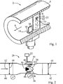
In
Das Wirbelströmungsmessgerät
In
In
Strömt beispielsweise feuchte Luft (Medium) durch eine Rohrleitung, in der das Wirbelströmungsmessgerät
Alternativ können die Prozessbedingungen bereits in der Rohrleitung derart sein, dass ein Teil des, in der feuchten Luft enthaltenen Wassersdampfs auskondensiert ist (bzw. alternativ ausgefroren ist) und in flüssiger (bzw. alternativ: fester) Phase (insbesondere als Tröpfchen) mitgeführt wird. Aufgrund des reduzierten Strömungsquerschnitts im Bereich des Messquerschnitts
Nachfolgend werden Ausführungsformen des erfindungsgemäßen Verfahrens und die Herleitung der jeweils relevanten, physikalischen Formeln erläutert. Wie in dem Fachgebiet bekannt ist, kann ein Strömungsfeld durch die Navier-Stokes-Gleichungen beschrieben werden. Für ein stationäres Kontrollvolumen lauten die Navier-Stokes-Gleichungen in integraler Form wie folgt, wobei durch die Gleichung (1) die Massenerhaltung, durch Gleichung (2) die Impulserhaltung und durch Gleichung (3) die Energieerhaltung ausgedrückt werden. Hereinafter, embodiments of the method according to the invention and the derivation of the respective relevant physical formulas will be explained. As is known in the art, a flow field may be described by the Navier-Stokes equations. For a steady state control volume, the Navier-Stokes equations in integral form are as follows, expressing mass conservation by equation (1), conservation of momentum by equation (2), and energy conservation by equation (3).


Dabei sind t die Zeit, V das ortsfeste Kontrollvolumen, ρ die Dichte, S die Grenzfläche des ortsfesten Kontrollvolumens, u → der Geschwindigkeitsvektor, n → der Normalenvektor der Grenzfläche, p der Druck, B → die spezifische Körperkraft, u der Geschwindigkeitsbetrag, τ der viskose Spannungstensor, e die spezifische, innere Energie, q → der Wärmestromvektor und Q die spezifische, volumetrische Energiezufuhr.Where t is the time, V the stationary control volume, ρ the density, S the interface of the fixed control volume, u → the velocity vector, n → the normal vector of the interface, p the pressure, B → the specific body force, u the velocity amount, τ the viscous stress tensor, e the specific internal energy, q → the heat flow vector and Q the specific, volumetric energy input.
Mit der Annahme, dass die Strömung stationär ist, ergibt sich aus der Massenerhaltung (vgl. Gleichung (1)): ![]()
![]()
Dies bedeutet anschaulich, dass der Massenstrom in das Kontrollvolumen hinein (in Gleichung (5) durch den Index 1 ausgedrückt) gleich dem Massenstrom aus dem Kontrollvolumen hinaus (in Gleichung (5) durch den Index 2 ausgedrückt) ist. Dieser Zusammenhang wird in der nachfolgenden Gleichung (5) ausgedrückt. Dies kann anhand der
In allgemeiner Form bedeutet dies, dass der, durch die nachfolgende Gleichung (6) ausgedrückte Massenstrom bzw. Massedurchfluss einer stationären Strömung in einem Rohr konstant ist. Dabei sind in Gleichung (6) m . der Massedurchfluss, ρ die Dichte, u die mittlere Strömungsgeschwindigkeit und A der verfügbare Strömungsquerschnitt. Insbesondere ändert sich der Massedurchfluss nicht entlang des Strömungspfades des Mediums. Dieses Prinzip wird bei dem erfindungsgemäßen Verfahren ausgenützt, wie unterhalb noch im Detail erläutert wird. Gemäß dem erfindungsgemäßen Verfahren wird nämlich der Massedurchfluss im Bereich des Messquerschnitts korrekt anhand der lokal, im Bereich des Messquerschnitts vorliegenden Prozessbedingungen bestimmt. Dieser Massedurchfluss liegt (bei Annahme einer stationären Strömung) an jeder Stelle entlang des Strömungspfades vor, unabhängig von etwaig auftretenden Dichteänderungen des strömenden Mediums.
Bei inkompressiblen Medien, wie beispielsweise bei Flüssigkeiten, gestaltet sich die Bestimmung des, im Anschlussrohrbereich vorliegenden Volumenstroms V .A ein Wirbelströmungsmessgerät relativ einfach. Die sensorisch erfassbare Wirbelablösefrequenz f der, durch den Staukörper gebildeten Wirbel ist über einen weiten Reynoldszahlbereich proportional zu der lokal, im Bereich des Messquerschnitts vorliegenden Strömungsgeschwindigkeit sowie zu dem lokal, im Bereich des Messquerschnitts vorliegenden Volumendurchfluss. Da bei inkompressiblen Medien die Dichte des Mediums entlang von dessen Strömungspfad konstant bleibt, ist die Wirbelablösefrequenz auch proportional zu dem Volumendurchfluss V .A im Anschlussrohrbereich sowie zu der Strömungsgeschwindigkeit uA im Anschlussrohrbereich, was durch einen entsprechenden Kalibrierfaktor kf ausgedrückt werden kann. Der Kalibrierfaktor kf ist dabei insbesondere spezifisch für den jeweiligen Typ von Wirbelströmungsmessgerät. Die erläuterten Beziehungen werden durch die nachfolgende Gleichung (7) ausgedrückt, in der mit AA der Strömungsquerschnitt im Anschlussrohrbereich bezeichnet wird: ![]()
![]()
Bei kompressiblen Medien hingehen ist die Dichte ρ eine Funktion des lokalen, statischen Drucks p und der statischen Temperatur T, was durch die nachfolgende Gleichung (8) ausgedrückt wird:
Bei einem ausschließlich gasförmig (d. h. einphasig) vorliegenden Medium kann die Abhängigkeit der Dichte von dem Druck und der statischen Temperatur relativ einfach bestimmt werden. Liegen die Prozessbedingungen im Bereich des Messquerschnitts jedoch in einem Bereich des Phasenübergangs von einem, in dem Medium enthaltenen Stoff, so wird die Dichte des Mediums zusätzlich dadurch bestimmt, zu welchen Anteilen der Stoff in den verschiedenen Phasen vorliegt. Dabei durchläuft nicht der gesamte Anteil des Stoffes schlagartig sondern allmählich solch einen Phasenübergang. Bei einem Phasenübergang wird jeweils eine Phasenübergangs-Enthalpie des betreffenden Phasenübergangs, wie beispielsweise eine Kondensationsenthalpie, frei bzw. aufgenommen.For a gaseous (i.e., monophasic) medium, the dependence of density on pressure and static temperature can be determined relatively easily. However, if the process conditions in the region of the measuring cross-section lie in a region of the phase transition of a substance contained in the medium, the density of the medium is additionally determined by what proportions the substance is present in the different phases. In this case, not the entire portion of the substance passes abruptly but gradually such a phase transition. In a phase transition, in each case a phase transition enthalpy of the relevant phase transition, such as, for example, a condensation enthalpy, is released or absorbed.
Aufgrund von dessen Funktionsweise kann durch das Wirbelströmungsmessgerät auch dann, wenn das Medium in zwei oder mehr Phasen vorliegt, relativ exakt die im Bereich des Messquerschnitts vorliegende Strömungsgeschwindigkeit u des Mediums (bzw. entsprechend auch dessen Volumendurchfluss) bestimmt werden. Aufgrund der hohen Dichteunterschiede zwischen flüssiger (bzw. alternativ: fester) und gasförmiger Phase nimmt selbst dann, wenn die flüssige (bzw. alternativ auch die feste) Phase einen erheblichen Massenanteil ausmacht, die gasförmige Phase den überwiegenden Anteil des Volumens ein. Vorzugsweise ist der Massenanteil xg der gasförmigen Phase > 0,5.Due to its mode of operation, the flow velocity u of the medium (or, correspondingly, its volume flow) present in the region of the measuring cross section can be determined relatively accurately by the vortex flow meter even if the medium is present in two or more phases. Due to the high density differences between liquid (or alternatively: solid) and gaseous phase, even if the liquid (or alternatively also the solid) phase makes up a considerable mass fraction, the gaseous phase occupies the predominant part of the volume. Preferably, the mass fraction x g of the gaseous phase is> 0.5.
Für die Bestimmung des Massedurchflusses muss die Dichte lokal im Bereich des Messquerschnitts möglichst exakt bestimmt werden. Die Bestimmung der Dichte des Mediums im Bereich des Messquerschnitts wird nachfolgend anhand des Phasen übergangs gasförmig-flüssig erläutert. Die Dichte wird bei sämtlichen erläuterten Ausführungsformen, wie nachfolgend im Detail erläutert wird, aus der spezifischen, totalen Enthalpie, aus der Strömungsgeschwindigkeit, aus dem statischen Druck und aus der statischen Temperatur bestimmt, wobei bei sämtlichen, physikalischen Größen auf den Bereich des Messquerschnitts Bezug genommen wird. Dabei wird die Dichte im Bereich des Messquerschnitts aus dem ersten Massenanteil des Stoffes (z. B. H2O) in der ersten (z. B. gasförmigen) Phase und dessen Dichte ρg im Bereich des Messquerschnitts. dem zweiten Massenanteil des Stoffes in der zweiten (z. B. flüssigen) Phase und dessen Dichte ρl im Bereich des Messquerschnitts sowie gegebenenfalls von weiteren, in dem Medium enthaltenen Stoffen (z. B. trockene Luft) in deren jeweiliger (z. B. gasförmiger) Phase und deren jeweiliger Dichten ρr im Bereich des Messquerschnitts bestimmt. Wird das Medium durch genau einen Stoff (z. B. H2O) gebildet, der bei den Prozessbedingungen sowohl in gasförmiger als auch in flüssiger Phase vorliegen kann, so kann die Dichte ρ des Mediums im Bereich des Messquerschnitts als Funktion des statischen Drucks p im Bereich des Messquerschnitts, der statischen Temperatur im Bereich des Messquerschnitts und dem Massenanteil der gasförmigen Phase xg ausgedrückt werden. Dieser Zusammenhang ist in der nachfolgenden Gleichung (9) dargestellt, wobei ρg(p, T) die Dichte der gasförmigen Phase dieses Stoffes in Abhängigkeit von dem statischen Druck p und der statischen Temperatur T und ρl(p, T) die Dichte der flüssigen Phase dieses Stoffes in Abhängigkeit von dem statischen Druck p und der statischen Temperatur T bilden. Die Druck- und Temperaturabhängigkeit der Dichte der jeweiligen Phase des jeweiligen Stoffes ist dabei bekannt (beispielsweise aus entsprechenden Korrelationen für den betreffenden Stoff erhältlich).To determine the mass flow, the density must be determined as accurately as possible locally in the area of the measuring cross section. The determination of the density of the medium in the region of the measuring cross-section will be explained below with reference to the phase transition gaseous-liquid. The density is determined in all of the illustrated embodiments, as will be explained in detail below, from the specific, total enthalpy, the flow rate, the static pressure and the static temperature, with reference to the area of the measuring cross section for all the physical quantities becomes. In this case, the density in the region of the measuring cross section is made up of the first mass fraction of the substance (eg H 2 O) in the first (eg gaseous) phase and its density ρ g in the region of the measuring cross section. the second mass fraction of the substance in the second (eg liquid) phase and its density ρ l in the region of the measurement cross-section and optionally of other substances contained in the medium (eg dry air) in their respective (eg gaseous) phase and their respective densities ρ r determined in the region of the measuring cross section. If the medium is formed by exactly one substance (eg H 2 O) which can be present in the process conditions both in gaseous and in liquid phase, then the density ρ of the medium in the region of the measuring cross section as a function of the static pressure p in the area of the measuring cross section, the static temperature in the area of the measuring cross section and the mass fraction of the gaseous phase x g are expressed. This relationship is shown in the following equation (9), where ρ g (p, T) is the density of the gaseous phase of this substance as a function of the static pressure p and the static temperature T and ρ l (p, T) the density of the liquid phase of this substance as a function of the static pressure p and the static temperature T form. The pressure and temperature dependence of the density of the respective phase of the respective substance is known (obtainable, for example, from corresponding correlations for the substance concerned).

Wird das Medium (z. B. feuchte Luft) aus mehreren Stoffen gebildet und weist es (genau) einen Stoff (z. B. H2O) auf, der zumindest bei einem Teil der möglichen Prozessbedingungen im Bereich des Messquerschnitts in zwei Phasen, vorliegend in der gasförmigen und der flüssigen Phase, vorliegt, so kann die Dichte ρ des Mediums im Bereich des Messquerschnitts als Funktion des statischen Drucks p im Bereich des Messquerschnitts, der statischen Temperatur im Bereich des Messquerschnitts, dem als bekannt vorausgesetzten Massenanteil x dieses Stoffes (Gesamtmasse des Stoffes relativ zu der Gesamtmasse des Mediums) und dem Massenanteil der gasförmigen Phase xg (Gesamtmasse des Stoffes in der gasförmigen Phase relativ zu der Gesamtmasse des Stoffes) im Bereich des Messquerschnitts entsprechend ausgedrückt werden. Dieser Zusammenhang ist in der nachfolgenden Gleichung (10) dargestellt, wobei ρr(p, T) die Dichte des restlichen, gasförmigen Mediums (z. B. trockene Luft) in Abhängigkeit von dem statischen Druck p und der statischen Temperatur T ist (diese Funktion der Dichte ρr ist bekannt): 
Wie anhand der Gleichungen (9) und (10) ersichtlich ist, kann die Dichte ρ des Mediums (z. B. feuchte Luft) im Bereich des Messquerschnitts aus dem ersten Massenanteil x·xg des Stoffes (z. B. H2O) in einer ersten (hier: gasförmigen) Phase und dessen Dichte ρg im Bereich des Messquerschnitts, dem zweiten Massenanteil x·(1 – xg) des Stoffes in einer zweiten (hier: flüssigen) Phase und dessen Dichte ρl im Bereich des Messquerschnitts sowie gegebenenfalls weiterer Massenanteile (1 – x) von weiteren, in dem Medium enthaltenen Stoffen (z. B. trockene Luft) in deren jeweiliger Phase (hier: gasförmig) und deren jeweiliger Dichten ρr im Bereich des Messquerschnitts ausgedrückt werden. Zur korrekten Bestimmung der Dichte ρ des Mediums muss folglich der Massenanteil der gasförmigen Phase xg bestimmt werden. Hierzu wird Gleichung (3) herangezogen, welche eine der Navier-Stokes-Gleichungen bildet und die Energieerhaltung ausdrückt. Unter den vereinfachenden Annahmen, dass eine stationäre Strömung vorliegt, dass keine Wärmequellen existieren, dass kein Wärmestrom zu bzw. von dem Medium weg auftritt, dass keine Reibung auftritt und dass keine Änderung der potentiellen Energie auftritt, sind der erste sowie der vierte bis siebte Term der Gleichung (3) jeweils gleich Null. Dementsprechend ergibt sich für die Energieerhaltung nachfolgende Gleichung (11): 
Dabei ist in Gleichung (11) h die spezifische Enthalpie, die sich, wie in Gleichung (12) angegeben ist, ausdrücken lässt. Weiterhin ist h0 die spezifische, totale Enthalpie des Mediums, die sich, wie in Gleichung (13) angegeben ist, ausdrücken lässt.
In Bezug auf das oberhalb erläuterte Kontrollvolumen gilt dementsprechend, dass der Strom der spezifischen, totalen Enthalpie in das Kontrollvolumen hinein (in Gleichung (14) durch den Index 1 ausgedrückt) gleich dem Strom der spezifischen, totalen Enthalpie aus dem Kontrollvolumen hinaus (in Gleichung (14) durch den Index 2 ausgedrückt) ist, was nachfolgend in Gleichung (14) ausgedrückt wird. Zusammen mit Gleichung (5) ergibt sich aus Gleichung (14) allgemein, dass der Strom der spezifischen, totalen Enthalpie h0 unter den oberhalb getroffenen (vereinfachenden) Annahmen konstant ist, was nachfolgend durch Gleichung (15) ausgedrückt wird.Accordingly, with respect to the control volume discussed above, the specific total enthalpy flow into the control volume (expressed by

Die spezifische, totale Enthalpie des Mediums kann ferner durch die Summe der kinetischen Energie des Mediums im Bereich des Messquerschnitts, der spezifischen Enthalpie hg(p, T) von dem Stoff (z. B. H2O) in der ersten (z. B. gasförmigen) Phase im Bereich des Messquerschnitts mal den ersten Massenanteil des Stoffes in der ersten Phase, der spezifischen Enthalpie hl(p, T) von dem Stoff in der zweiten (z. B. flüssigen) Phase im Bereich des Messquerschnitts mal den zweiten Massenanteil des Stoffes in der zweiten Phase und gegebenenfalls weiterer, spezifischer Enthalpien hr(p, T) von weiteren, in dem Medium enthaltenen Stoffen (z. B. trockene Luft) in deren jeweiliger Phase (insbesondere gasförmig) mal deren jeweiligen Massenanteilen ausgedrückt werden. Wird das Medium aus ausschließlich einem Stoff (z. B. H2O), der zumindest bei einem Teil der möglichen Prozessbedingungen in zwei Phasen vorliegt, gebildet, so ergibt sich für die angegebene Beziehung die Gleichung (16). Wird das Medium (z. B. feuchte Luft) aus mehreren Stoffen gebildet und weist es (genau) einen Stoff (z. B. H2O) auf, der zumindest bei einem Teil der möglichen Prozessbedingungen im Bereich des Messquerschnitts in zwei Phasen, vorliegend in der gasförmigen und der flüssigen Phase, vorliegt, so ergibt sich für die angegebene Beziehung die Gleichung (18). Werden diese Gleichungen (16) bzw. (18) nach dem Massenanteil des Stoffes (z. B. H2O) in der ersten (z. B. gasförmigen) Phase aufgelöst, so ergeben sich die Gleichungen (17) bzw. (19). The specific, total enthalpy of the medium can also be determined by the sum of the kinetic energy of the medium in the region of the measuring cross section, the specific enthalpy h g (p, T) of the substance (eg H 2 O) in the first (e.g. Gaseous) phase in the region of the measuring cross section times the first mass fraction of the substance in the first phase, the specific enthalpy h l (p, T) of the substance in the second (eg liquid) phase in the region of the measuring cross section times second mass fraction of the substance in the second phase and optionally further specific enthalpies h r (p, T) of further substances contained in the medium (eg dry air) in their respective phase (in particular gaseous) expressed times their respective mass fractions become. If the medium is formed exclusively from a substance (eg H 2 O) which is present in at least part of the possible process conditions in two phases, equation (16) results for the given relationship. If the medium (eg moist air) is formed from several substances and has (exactly) a substance (eg H 2 O) which, at least for a part of the possible process conditions in the region of the measuring cross section, has two phases, present in the gaseous and the liquid phase, the equation (18) results for the given relationship. If these equations (16) or (18) are resolved according to the mass fraction of the substance (eg H 2 O) in the first (eg gaseous) phase, the equations (17) and (19 ).

Dabei können die spezifischen Enthalpie hg(p, T) des Stoffes (z. B. H2O) in der ersten (z. B. gasförmigen) Phase, die spezifische Enthalpie hl(p, T) des Stoffes in der zweiten (z. B. flüssigen) Phase sowie die spezifische Enthalpie hr(p, T) von weiteren, in dem Medium enthaltenen Stoffen (z. B. trockene Luft) anhand der, im Bereich des Messquerschnitts vorliegenden Werte für die statische Temperatur T und den statischen Druck p anhand von Korrelationen, die für die verschiedenen Stoffe existieren, bestimmt werden. Um den Massenanteil des Stoffes (z. B. H2O) in der ersten (z. B. gasförmigen) Phase bestimmen zu können, muss folglich noch die spezifische, totale Enthalpie h0 des Mediums in dem Bereich des Messquerschnitts bestimmt werden. Möglichkeiten hierzu werden nachfolgend erläutert.In this case, the specific enthalpy h g (p, T) of the substance (eg H 2 O) in the first (eg gaseous) phase, the specific enthalpy h l (p, T) of the substance in the second (eg liquid) phase and the specific enthalpy h r (p, T) of further substances contained in the medium (eg dry air) on the basis of the values for the static temperature T and the static pressure p are determined by correlations that exist for the different substances. In order to be able to determine the mass fraction of the substance (eg H 2 O) in the first (eg gaseous) phase, it is therefore still necessary to determine the specific, total enthalpy h 0 of the medium in the region of the measurement cross section. Options for this are explained below.
Wie oberhalb unter Bezugnahme auf die Gleichungen (14) und (15) erläutert wird, ist unter Voraussetzung der oberhalb getroffenen, vereinfachenden Annahmen der Strom der spezifischen, totalen Enthalpie h0 entlang dem Strömungspfad des Mediums konstant. Wird das Medium aus einem (zumindest weitgehend im thermodynamischen Gleichgewicht befindlichen) System entnommen, in dem das Medium vor dessen Entnahme ruht, so kann die spezifische, totale Enthalpie h0 des strömenden Mediums im Bereich des Messquerschnitts aus dem statischen (bzw. totalen) Druck p0 und der statischen (bzw. totalen) Temperatur T0, die das Medium innerhalb dieses Systems aufweist, bestimmt werden. Das System kann beispielsweise durch einen Dampfkessel mit einem bekannten Dampfkesseldruck und einer bekannten Dampfkesseltemperatur gebildet werden. Alternativ kann das System für den Fall, dass durch die betreffende Rohrleitung Umgebungsluft angesaugt wird, durch den Umgebungsdruck und die Umgebungstemperatur charakterisiert werden. Das Medium liegt in dem System insbesondere vollständig gasförmig vor. Die spezifische, totale Enthalpie h0 entspricht in dem System, in dem das betreffende Medium ruht (und in einem thermodynamischen Gleichgewicht vorliegt), der spezifischen Enthalpie h(p0, T0). Die spezifische Enthalpie h(p0, T0) kann für den jeweiligen Stoff in dessen jeweiliger Phase anhand bekannter Korrelationen aus dem (statischen bzw. totalen) Druck p0 und der (statischen bzw. totalen) Temperatur T0 des Mediums in dem System bestimmt werden. Setzt sich das Medium aus mehreren Stoffen (Elemente, wie z. B. O2, oder Verbindungen, wie z. B. H2O) mit jeweils bekannten Massenanteilen zusammen, so kann die spezifische Enthalpie h(p0, T0) des Mediums in dem System jeweils separat für die verschiedenen Stoffe in deren jeweiliger Phase (aus dem statischen Druck p0 und der statischen Temperatur T0) bestimmt werden. Anhand der jeweiligen Massenanteile der verschiedenen Stoffe in dem System kann dann die spezifischen Enthalpie h(p0, T0) für das gesamte Medium bestimmt werden. In dem Bereich des Messquerschnitts setzt sich die spezifische, totale Enthalpie h0 des Mediums aus der spezifischen Enthalpie h(p, T) und der spezifischen, kinetischen Energie u2/2 zusammen. Dieser Zusammenhang ist in der nachfolgenden Gleichung (20) ausgedrückt.
Findet ein Wärmeübergang auf das Medium entlang von dessen Strömungspfad statt, so kann die spezifische, totale Enthalpie h0,b des Mediums im Bereich des Messquerschnitts auch aus einer bekannten, spezifischen, totalen Enthalpie h0,a des Mediums in einem stromaufwärts oder stromabwärts von dem Messquerschnitt gelegenen Abschnitt unter Berücksichtigung eines Wärmeübergangs auf das strömende Medium von dem Abschnitt (Index a) bis zu dem Messquerschnitt (Index b) bestimmt werden. Diese Variante wird durch die nachfolgende Gleichung (21) ausgedrückt, wobei der Term![]()
![]()

In Gleichung (21) geht auch der Massedurchfluss des Mediums ein, dessen genaue Bestimmung gerade Gegenstand des erfindungsgemäßen Verfahrens ist. Diese Problematik kann insbesondere iterativ gelöst werden. Hierzu kann insbesondere zunächst die bekannte spezifische, totale Enthalpie h0,a, die in dem Abschnitt (Index a) vorliegt, als spezifische, totale Enthalpie des Mediums in dem Bereich des Messquerschnitts eingesetzt werden (z. B. in Gleichung (17) oder (19)). Daraus kann dann nach dem erfindungsgemäßen Verfahren der Massedurchfluss bestimmt werden (wie es unterhalb noch im Detail erläutert wird). Der ermittelte Massedurchfluss kann dann wiederum in Gleichung (21) eingesetzt werden. Daraus kann dann die spezifische, totale Enthalpie h0,b im Bereich des Messquerschnitts nach Gleichung (21) bestimmt werden. Diese kann dann wiederum als spezifische Enthalpie des Mediums im Bereich des Messquerschnitts zur Bestimmung des Massedurchflusses nach dem erfindungsgemäßen Verfahren herangezogen werden. Dabei können so viele Iterationen durchgeführt werden, bis ein ausreichend korrektes Ergebnis erhalten wird bzw. bis sich die erhaltenen Werte für den Massedurchfluss nur noch in geringem Maß von Iteration zu Iteration ändern.Equation (21) also includes the mass flow rate of the medium, the exact determination of which is the subject matter of the method according to the invention. This problem can be solved in particular iteratively. In particular, the known specific total enthalpy h 0, a , which is present in the section (index a), can be used as a specific, total enthalpy of the medium in the region of the measuring cross section (eg in equation (17) or (19)). From this, the mass flow rate can then be determined by the method according to the invention (as will be explained below in detail). The determined mass flow can then be used again in equation (21). From this, the specific, total enthalpy h 0, b in the area of the measuring cross-section can then be determined according to equation (21). This can in turn be used as a specific enthalpy of the medium in the region of the measuring cross section for determining the mass flow rate according to the method according to the invention. In this case, it is possible to carry out so many iterations until a sufficiently correct result is obtained or until the values obtained for the mass flow rate change only slightly from iteration to iteration.
Ferner besteht in Bezug auf Gleichung (21) die Möglichkeit, dass für die bekannte, spezifische, totale Enthalpie h0,a des Mediums dann, wenn das Medium aus einem ruhenden System, wie es oberhalb beschrieben ist, entnommen wird, durch die spezifische, totale Enthalpie des Mediums in diesem System gebildet wird (vgl. Gleichung (20)). Durch Anwendung der Gleichung (21) kann dann ein Wärmeübergang auf das strömende Medium auf dem Weg von dem System bis zu dem Messquerschnitt berücksichtigt werden.Further, with respect to equation (21), for the known, specific, total enthalpy h 0, a of the medium, when the medium is taken from a quiescent system as described above, there is the possibility of total enthalpy of the medium is formed in this system (see equation (20)). By applying equation (21), a heat transfer to the flowing medium on the way from the system to the measuring cross section can then be taken into account.
Die nach dem Verfahren nach Gleichung (20) und/oder nach dem Verfahren nach Gleichung (21) erhaltene, spezifische, totale Enthalpie h0 des Mediums in dem Bereich des Messquerschnitts kann dann in die Gleichung (17) bzw. (19) eingesetzt werden. Daraus kann dann der Masseanteil xg des Stoffes (z. B. H2O) in der ersten Phase im Bereich des Messquerschnitts berechnet werden. Der Masseanteil xg kann dann wiederum in die Gleichung (9) bzw. (10) eingesetzt werden. Daraus kann dann die Dichte des Mediums im Bereich des Messquerschnitts bestimmt werden. Der Massedurchfluss wird anschließend gemäß Gleichung (6) aus der bestimmten Strömungsgeschwindigkeit u des Mediums im Bereich des Messquerschnitts, der bestimmten Dichte ρ des Mediums im Bereich des Messquerschnitts und aus dem Strömungsquerschnitt A des Mediums im Bereich des Messquerschnitts bestimmt.The specific total enthalpy h 0 of the medium in the region of the measuring cross section obtained by the method according to equation (20) and / or by the method according to equation (21) can then be inserted into equation (17) or (19) , From this, the mass fraction x g of the substance (eg H 2 O) in the first phase in the region of the measuring cross section can then be calculated. The mass fraction x g can then be used again in the equation (9) or (10). From this, the density of the medium in the region of the measuring cross section can then be determined. The mass flow is then determined according to equation (6) from the determined flow velocity u of the medium in the region of the measuring cross section, the specific density ρ of the medium in the region of the measuring cross section and from the flow cross section A of the medium in the region of the measuring cross section.
Soll der Volumendurchfluss des Mediums im Anschlussrohrbereich bestimmt werden, so ist der gemäß Gleichung (6) erhaltene Massedurchfluss noch durch die Dichte des Mediums, die im Anschlussrohrbereich vorliegt, (vgl. z. B. ρ1 in
Die vorliegende Erfindung ist nicht auf die, unter Bezugnahme auf die Figuren erläuterten Ausführungsbeispiele beschränkt. Beispielsweise kann das Wirbelströmungsmessgerät auf verschiedene Weisen, wie es insbesondere aus dem Stand der Technik bekannt ist, aufgebaut sein. Insbesondere kann der grundsätzliche Aufbau einem Wirbelströmungsmessgerät entsprechen, wie es im einleitenden Teil erläutert wurde. Bezüglich der Anordnung und Ausbildung des Wirbelsensors sind verschiedene Varianten, wie beispielsweise die integrale Ausbildung in dem Staukörper oder die separate Ausbildung als Paddel, das stromabwärts von dem Staukörper angeordnet ist, möglich. Weiterhin sind unterschiedliche Formen des Staukörpers und unterschiedliche Ausbildungen der Abrisskanten möglich. Ferner können im Rahmen der Bestimmung der Dichte des Mediums im Bereich des Messquerschnitts auch weitere Effekte, wie beispielsweise Reibungseffekte, berücksichtigt werden. Wie dem Fachmann geläufig ist, kann dazu insbesondere auch noch die Gleichung (2), welche die Impulserhaltung betrifft, miteinbezogen werden.The present invention is not limited to the embodiments explained with reference to the figures. For example, the vortex flow meter may be constructed in various ways, as known in particular from the prior art. In particular, the basic structure may correspond to a vortex flow meter, as explained in the introductory part. With regard to the arrangement and design of the vortex sensor, various variants, such as the integral formation in the bluff body or the separate formation as a paddle, which is arranged downstream of the bluff body, are possible. Furthermore, different shapes of the bluff body and different configurations of the fouling edges are possible. Furthermore, as part of the determination of the density of the medium in the region of the measuring cross section, other effects, such as frictional effects, are taken into account. As is known to the person skilled in the art, equation (2), which relates to the conservation of momentum, may be included in particular.
Die oberhalb erläuterten Ausführungsbeispiele betrafen jeweils den Phasenübergang zwischen gasförmig und flüssig. Alternativ kann das erfindungsgemäße Verfahren entsprechend für den Phasenübergang zwischen gasförmig und fest realisiert werden. In letzterem Fall sind anstelle der druck- und temperaturabhängigen Dichte und druck- und temperaturabhängigen spezifischen Enthalpie des Stoffes in der flüssigen Phase die druck- und temperaturabhängige Dichte und die druck- und temperaturabhängige spezifische Enthalpie des Stoffes in der festen Phase heranzuziehen.The embodiments explained above each related to the phase transition between gaseous and liquid. Alternatively, the method according to the invention can be realized correspondingly for the phase transition between gaseous and solid. In the latter case, instead of the pressure and temperature-dependent density and pressure and temperature-dependent specific enthalpy of the substance in the liquid phase, the pressure and temperature-dependent density and the pressure and temperature-dependent specific enthalpy of the substance in the solid phase are to be used.
Weiterhin kann für den Fall, dass der statische Druck p nicht lokal an der betreffenden Stelle (z. B. im Bereich des Messquerschnitts; im Anschlussrohrbereich, etc.) gemessen werden kann, der statische Druck p gemäß der nachfolgenden Gleichung (22) berechnet werden: ![]()
![]()
Dabei ist pt der Totaldruck und M die Mach-Zahl des Mediums. Die Mach-Zahl M wird durch nachfolgende Gleichung (23) ausgedrückt, wobei u die Strömungsgeschwindigkeit des Mediums und a die Schallgeschwindigkeit ist. γ wird durch die Gleichung (24) ausgedrückt, wobei cv die spezifische Wärmekapazität des Mediums bei konstantem Volumen und cp die spezifische Wärmekapazität unter konstantem Druck ist.Here, p t is the total pressure and M is the Mach number of the medium. The Mach number M is expressed by the following equation (23), where u is the flow velocity of the medium and a is the sound velocity. γ is expressed by the equation (24), where c v is the specific heat capacity of the medium at constant volume and c p is the specific heat capacity under constant pressure.
![]()
![]()
Claims (14)
Priority Applications (5)
| Application Number | Priority Date | Filing Date | Title |
|---|---|---|---|
| DE102010064278A DE102010064278A1 (en) | 2010-12-28 | 2010-12-28 | Method for density correction in vortex flow meter |
| US13/976,533 US9476741B2 (en) | 2010-12-28 | 2011-11-23 | Method for density correction in a vortex, flow measuring device |
| EP11788136.7A EP2659235B8 (en) | 2010-12-28 | 2011-11-23 | Method for density correction in a vortex flowmeter |
| CN201180063390.1A CN103282749B (en) | 2010-12-28 | 2011-11-23 | Method for density correction in an eddy-low measuring instrument |
| PCT/EP2011/070864 WO2012089430A1 (en) | 2010-12-28 | 2011-11-23 | Method for density correction in an eddy-flow measuring instrument |
Applications Claiming Priority (1)
| Application Number | Priority Date | Filing Date | Title |
|---|---|---|---|
| DE102010064278A DE102010064278A1 (en) | 2010-12-28 | 2010-12-28 | Method for density correction in vortex flow meter |
Publications (1)
| Publication Number | Publication Date |
|---|---|
| DE102010064278A1 true DE102010064278A1 (en) | 2012-06-28 |
Family
ID=45044585
Family Applications (1)
| Application Number | Title | Priority Date | Filing Date |
|---|---|---|---|
| DE102010064278A Withdrawn DE102010064278A1 (en) | 2010-12-28 | 2010-12-28 | Method for density correction in vortex flow meter |
Country Status (5)
| Country | Link |
|---|---|
| US (1) | US9476741B2 (en) |
| EP (1) | EP2659235B8 (en) |
| CN (1) | CN103282749B (en) |
| DE (1) | DE102010064278A1 (en) |
| WO (1) | WO2012089430A1 (en) |
Cited By (3)
| Publication number | Priority date | Publication date | Assignee | Title |
|---|---|---|---|---|
| DE102012112976A1 (en) * | 2012-12-21 | 2014-06-26 | Endress + Hauser Flowtec Ag | Method and vortex flow meter for determining the mass flow ratio of a multiphase flow |
| DE102013110243A1 (en) * | 2013-09-17 | 2015-04-02 | Endress + Hauser Flowtec Ag | Method for monitoring a measuring device of automation technology |
| CN110207852A (en) * | 2019-05-24 | 2019-09-06 | 中国航天空气动力技术研究院 | A kind of electro-arc heater air-flow enthalpy Fast measurement system and method |
Families Citing this family (7)
| Publication number | Priority date | Publication date | Assignee | Title |
|---|---|---|---|---|
| US9322683B2 (en) * | 2014-05-12 | 2016-04-26 | Invensys Systems, Inc. | Multivariable vortex flowmeter |
| CN104374436A (en) * | 2014-11-18 | 2015-02-25 | 中环天仪股份有限公司 | Integrated detection structure of vortex flowmeter |
| US10175083B1 (en) * | 2017-08-30 | 2019-01-08 | Schneider Electric Systems Usa, Inc. | Vortex flowmeter having injection cleaning ports |
| TWI721460B (en) * | 2018-07-13 | 2021-03-11 | 美商愛康運動與健康公司 | Cycling shoe power sensors |
| DE102018119805B4 (en) * | 2018-08-15 | 2020-03-19 | SIKA Dr. Siebert & Kühn GmbH & Co. KG | Device and method for determining the flow velocity of a fluid in a hollow body |
| RU201794U1 (en) * | 2020-07-07 | 2021-01-13 | Акционерное общество "Научно-исследовательский институт Приборостроения имени В.В. Тихомирова" | Flow meter |
| DE102021117707A1 (en) | 2021-07-08 | 2023-01-12 | Endress+Hauser Flowtec Ag | Measuring system for measuring a flow parameter of a fluid substance flowing in a pipeline |
Citations (7)
| Publication number | Priority date | Publication date | Assignee | Title |
|---|---|---|---|---|
| US4574643A (en) * | 1984-10-31 | 1986-03-11 | Alberta Oil Sands Technology And Research Authority | Two phase flowmeter |
| US4984456A (en) * | 1988-12-19 | 1991-01-15 | Toyota Jidosha Kabushiki Kaisha | Device for detecting a mass flow of air fed into an engine cylinder |
| EP0666468A2 (en) * | 1994-02-04 | 1995-08-09 | The Foxboro Company | Multimeasurement replaceable vortex sensor |
| US6170338B1 (en) * | 1997-03-27 | 2001-01-09 | Rosemont Inc. | Vortex flowmeter with signal processing |
| WO2004023081A2 (en) * | 2002-09-06 | 2004-03-18 | Invensys Systems, Inc. | Multi-measurement vortex flow meter |
| US20080141769A1 (en) * | 2006-12-18 | 2008-06-19 | Schmidt Eric C | Vortex flowmeter with temperature compensation |
| DE102007030690A1 (en) * | 2007-06-30 | 2009-05-07 | Endress + Hauser Flowtec Ag | Measuring system for a medium flowing in a process line |
Family Cites Families (7)
| Publication number | Priority date | Publication date | Assignee | Title |
|---|---|---|---|---|
| US6298734B1 (en) * | 1999-03-17 | 2001-10-09 | Vortek Instruments Llc | Rocker style sensor system for use in a vortex shedding flowmeter |
| ATE549602T1 (en) * | 2002-01-23 | 2012-03-15 | Cidra Corporate Services Inc | DEVICE AND METHOD FOR MEASURING PARAMETERS OF A MIXTURE WITH SOLID PARTICLES SUSPENDED IN A FLUID FLOWING IN A PIPE |
| US7032432B2 (en) * | 2002-01-23 | 2006-04-25 | Cidra Corporation | Apparatus and method for measuring parameters of a mixture having liquid droplets suspended in a vapor flowing in a pipe |
| CA2513982C (en) * | 2003-01-22 | 2013-12-24 | David L. Hagen | Reactor |
| US7533579B2 (en) * | 2006-01-19 | 2009-05-19 | Invensys Systems, Inc. | Reduced bore vortex flowmeter having a stepped intake |
| PL1933097T3 (en) | 2006-12-07 | 2013-09-30 | Grundfos Management As | Method for controlling a variable speed circulation pump for heating system |
| US8447536B2 (en) * | 2007-06-30 | 2013-05-21 | Endress + Hauser Flowtec Ag | Medium density measuring system |
-
2010
- 2010-12-28 DE DE102010064278A patent/DE102010064278A1/en not_active Withdrawn
-
2011
- 2011-11-23 US US13/976,533 patent/US9476741B2/en active Active
- 2011-11-23 WO PCT/EP2011/070864 patent/WO2012089430A1/en active Application Filing
- 2011-11-23 EP EP11788136.7A patent/EP2659235B8/en active Active
- 2011-11-23 CN CN201180063390.1A patent/CN103282749B/en active Active
Patent Citations (7)
| Publication number | Priority date | Publication date | Assignee | Title |
|---|---|---|---|---|
| US4574643A (en) * | 1984-10-31 | 1986-03-11 | Alberta Oil Sands Technology And Research Authority | Two phase flowmeter |
| US4984456A (en) * | 1988-12-19 | 1991-01-15 | Toyota Jidosha Kabushiki Kaisha | Device for detecting a mass flow of air fed into an engine cylinder |
| EP0666468A2 (en) * | 1994-02-04 | 1995-08-09 | The Foxboro Company | Multimeasurement replaceable vortex sensor |
| US6170338B1 (en) * | 1997-03-27 | 2001-01-09 | Rosemont Inc. | Vortex flowmeter with signal processing |
| WO2004023081A2 (en) * | 2002-09-06 | 2004-03-18 | Invensys Systems, Inc. | Multi-measurement vortex flow meter |
| US20080141769A1 (en) * | 2006-12-18 | 2008-06-19 | Schmidt Eric C | Vortex flowmeter with temperature compensation |
| DE102007030690A1 (en) * | 2007-06-30 | 2009-05-07 | Endress + Hauser Flowtec Ag | Measuring system for a medium flowing in a process line |
Cited By (5)
| Publication number | Priority date | Publication date | Assignee | Title |
|---|---|---|---|---|
| DE102012112976A1 (en) * | 2012-12-21 | 2014-06-26 | Endress + Hauser Flowtec Ag | Method and vortex flow meter for determining the mass flow ratio of a multiphase flow |
| DE102013110243A1 (en) * | 2013-09-17 | 2015-04-02 | Endress + Hauser Flowtec Ag | Method for monitoring a measuring device of automation technology |
| US10175089B2 (en) | 2013-09-17 | 2019-01-08 | Endress + Hauser Flowtec Ag | Method for monitoring a measuring device of automation technology |
| CN110207852A (en) * | 2019-05-24 | 2019-09-06 | 中国航天空气动力技术研究院 | A kind of electro-arc heater air-flow enthalpy Fast measurement system and method |
| CN110207852B (en) * | 2019-05-24 | 2020-09-18 | 中国航天空气动力技术研究院 | Rapid measurement system and method for enthalpy value of airflow of electric arc heater |
Also Published As
| Publication number | Publication date |
|---|---|
| US20130282309A1 (en) | 2013-10-24 |
| US9476741B2 (en) | 2016-10-25 |
| EP2659235A1 (en) | 2013-11-06 |
| CN103282749A (en) | 2013-09-04 |
| WO2012089430A1 (en) | 2012-07-05 |
| EP2659235B1 (en) | 2020-09-16 |
| EP2659235B8 (en) | 2021-01-20 |
| CN103282749B (en) | 2017-05-10 |
Similar Documents
| Publication | Publication Date | Title |
|---|---|---|
| DE102010064278A1 (en) | Method for density correction in vortex flow meter | |
| EP3537124B1 (en) | Method and system for non-intrusive determining of a temperature of a fluid flowing through a conduit section | |
| DE112004000752B4 (en) | Two-phase vapor measurement system | |
| DE102007052041B4 (en) | Method for operating a density measuring device and device for density measurement | |
| DE60005669T2 (en) | FLOW MEASUREMENT METHOD FOR MULTI-PHASE FLOWS BY MEANS OF A VENTURI FLOW METER | |
| EP3021117A1 (en) | Method and measuring device for the determination of specific values for the type of gas | |
| DE102010040396A1 (en) | Flow meter for detecting a property of a fluid medium | |
| DE3239126A1 (en) | FLOWMETER FOR FLUIDE | |
| DE102008041145A1 (en) | Sensor arrangement for determining a parameter of a fluid medium | |
| DE102012218758A1 (en) | Sensor arrangement for determining the moisture content of a flowing in a main flow fluid medium | |
| EP3325923B1 (en) | Flow meter according to the vortex counting principle | |
| EP2936082A1 (en) | Method and vortex flow meter for determining the mass flow ratio of a multiphase flow | |
| DE102010040600A1 (en) | Method for detecting a blockage in a Coriolis flowmeter | |
| DE102008013224A1 (en) | Measuring system for determining and/or monitoring flow of measuring medium through measuring tube, has measuring tube, where signal path runs and partly lies in partial volume of tube on plane | |
| DE102008055032B4 (en) | Arrangement and method for multiphase flow measurement | |
| EP2041523B1 (en) | Measuring arrangement for flow measurement in a channel | |
| WO2016020277A1 (en) | Magnetoinductive flowmeter having a plurality of measuring electrode pairs and different measuring tube cross sections | |
| DE102007037394A1 (en) | Flow meter for a medium through a pipeline measures pressure at a diaphragm reducing the pipe cross section, and the difference between two temperature sensors | |
| DE102012001573B4 (en) | Method for measuring a flow rate of a flowing gas and flow meter | |
| DE102019125682A1 (en) | Arrangement and method for recognizing and correcting an incorrect flow measurement | |
| Coleman | Effects of suspended sediment on open channel velocity distributions | |
| Zhai et al. | Measurements on interfacial characteristics and droplet entrainment in horizontal liquid–liquid flows: A comparison of PLIF versus WMS | |
| EP0686254A1 (en) | Vortex-type flowmeter with a baffle element | |
| DE102012209149A1 (en) | Ultrasonic sensor e.g. ultrasonic flow meter for detecting property of fluid medium in air tract of engine of motor vehicle, has flow control element which is comprised in upstream and downstream of measuring element | |
| DE102015112930B4 (en) | Electromagnetic flow meter |
Legal Events
| Date | Code | Title | Description |
|---|---|---|---|
| R163 | Identified publications notified | ||
| R012 | Request for examination validly filed | ||
| R119 | Application deemed withdrawn, or ip right lapsed, due to non-payment of renewal fee |