DE102010063243A1 - Quick-change system and operating method of a container-handling machine - Google Patents
Quick-change system and operating method of a container-handling machine Download PDFInfo
- Publication number
- DE102010063243A1 DE102010063243A1 DE102010063243A DE102010063243A DE102010063243A1 DE 102010063243 A1 DE102010063243 A1 DE 102010063243A1 DE 102010063243 A DE102010063243 A DE 102010063243A DE 102010063243 A DE102010063243 A DE 102010063243A DE 102010063243 A1 DE102010063243 A1 DE 102010063243A1
- Authority
- DE
- Germany
- Prior art keywords
- machine
- securing
- quick
- change system
- holder
- Prior art date
- Legal status (The legal status is an assumption and is not a legal conclusion. Google has not performed a legal analysis and makes no representation as to the accuracy of the status listed.)
- Withdrawn
Links
- 238000011017 operating method Methods 0.000 title claims abstract description 9
- 230000009471 action Effects 0.000 claims abstract description 9
- 238000012937 correction Methods 0.000 claims abstract description 6
- 238000000034 method Methods 0.000 claims abstract description 6
- 230000001419 dependent effect Effects 0.000 claims abstract description 5
- 230000008859 change Effects 0.000 claims description 32
- 238000010438 heat treatment Methods 0.000 claims description 21
- 238000000071 blow moulding Methods 0.000 claims description 10
- 238000001514 detection method Methods 0.000 claims description 9
- 238000012806 monitoring device Methods 0.000 claims description 7
- 238000007664 blowing Methods 0.000 claims description 4
- 230000001939 inductive effect Effects 0.000 claims description 3
- 230000005291 magnetic effect Effects 0.000 claims description 3
- 230000005693 optoelectronics Effects 0.000 claims description 2
- 239000000047 product Substances 0.000 description 11
- 238000003780 insertion Methods 0.000 description 2
- 230000037431 insertion Effects 0.000 description 2
- 230000007246 mechanism Effects 0.000 description 2
- 238000012545 processing Methods 0.000 description 2
- 238000007669 thermal treatment Methods 0.000 description 2
- BUHVIAUBTBOHAG-FOYDDCNASA-N (2r,3r,4s,5r)-2-[6-[[2-(3,5-dimethoxyphenyl)-2-(2-methylphenyl)ethyl]amino]purin-9-yl]-5-(hydroxymethyl)oxolane-3,4-diol Chemical compound COC1=CC(OC)=CC(C(CNC=2C=3N=CN(C=3N=CN=2)[C@H]2[C@@H]([C@H](O)[C@@H](CO)O2)O)C=2C(=CC=CC=2)C)=C1 BUHVIAUBTBOHAG-FOYDDCNASA-N 0.000 description 1
- 206010031009 Oral pain Diseases 0.000 description 1
- 230000008901 benefit Effects 0.000 description 1
- 238000006243 chemical reaction Methods 0.000 description 1
- 230000002950 deficient Effects 0.000 description 1
- 238000013461 design Methods 0.000 description 1
- 230000003292 diminished effect Effects 0.000 description 1
- 238000005553 drilling Methods 0.000 description 1
- 238000004146 energy storage Methods 0.000 description 1
- 210000003746 feather Anatomy 0.000 description 1
- 230000000977 initiatory effect Effects 0.000 description 1
- 230000007257 malfunction Effects 0.000 description 1
- 239000005022 packaging material Substances 0.000 description 1
- 238000010008 shearing Methods 0.000 description 1
- 230000035939 shock Effects 0.000 description 1
- 230000008054 signal transmission Effects 0.000 description 1
- 239000006228 supernatant Substances 0.000 description 1
- 230000009885 systemic effect Effects 0.000 description 1
- 230000007704 transition Effects 0.000 description 1
Images


Classifications
-
- B—PERFORMING OPERATIONS; TRANSPORTING
- B29—WORKING OF PLASTICS; WORKING OF SUBSTANCES IN A PLASTIC STATE IN GENERAL
- B29C—SHAPING OR JOINING OF PLASTICS; SHAPING OF MATERIAL IN A PLASTIC STATE, NOT OTHERWISE PROVIDED FOR; AFTER-TREATMENT OF THE SHAPED PRODUCTS, e.g. REPAIRING
- B29C49/00—Blow-moulding, i.e. blowing a preform or parison to a desired shape within a mould; Apparatus therefor
- B29C49/42—Component parts, details or accessories; Auxiliary operations
- B29C49/48—Moulds
-
- B—PERFORMING OPERATIONS; TRANSPORTING
- B29—WORKING OF PLASTICS; WORKING OF SUBSTANCES IN A PLASTIC STATE IN GENERAL
- B29C—SHAPING OR JOINING OF PLASTICS; SHAPING OF MATERIAL IN A PLASTIC STATE, NOT OTHERWISE PROVIDED FOR; AFTER-TREATMENT OF THE SHAPED PRODUCTS, e.g. REPAIRING
- B29C49/00—Blow-moulding, i.e. blowing a preform or parison to a desired shape within a mould; Apparatus therefor
- B29C49/42—Component parts, details or accessories; Auxiliary operations
- B29C49/64—Heating or cooling preforms, parisons or blown articles
- B29C49/68—Ovens specially adapted for heating preforms or parisons
-
- B—PERFORMING OPERATIONS; TRANSPORTING
- B29—WORKING OF PLASTICS; WORKING OF SUBSTANCES IN A PLASTIC STATE IN GENERAL
- B29C—SHAPING OR JOINING OF PLASTICS; SHAPING OF MATERIAL IN A PLASTIC STATE, NOT OTHERWISE PROVIDED FOR; AFTER-TREATMENT OF THE SHAPED PRODUCTS, e.g. REPAIRING
- B29C49/00—Blow-moulding, i.e. blowing a preform or parison to a desired shape within a mould; Apparatus therefor
- B29C49/42—Component parts, details or accessories; Auxiliary operations
- B29C49/78—Measuring, controlling or regulating
-
- B—PERFORMING OPERATIONS; TRANSPORTING
- B29—WORKING OF PLASTICS; WORKING OF SUBSTANCES IN A PLASTIC STATE IN GENERAL
- B29C—SHAPING OR JOINING OF PLASTICS; SHAPING OF MATERIAL IN A PLASTIC STATE, NOT OTHERWISE PROVIDED FOR; AFTER-TREATMENT OF THE SHAPED PRODUCTS, e.g. REPAIRING
- B29C49/00—Blow-moulding, i.e. blowing a preform or parison to a desired shape within a mould; Apparatus therefor
- B29C49/42—Component parts, details or accessories; Auxiliary operations
- B29C49/48—Moulds
- B29C2049/4856—Mounting, exchanging or centering moulds or parts thereof
-
- B—PERFORMING OPERATIONS; TRANSPORTING
- B29—WORKING OF PLASTICS; WORKING OF SUBSTANCES IN A PLASTIC STATE IN GENERAL
- B29C—SHAPING OR JOINING OF PLASTICS; SHAPING OF MATERIAL IN A PLASTIC STATE, NOT OTHERWISE PROVIDED FOR; AFTER-TREATMENT OF THE SHAPED PRODUCTS, e.g. REPAIRING
- B29C49/00—Blow-moulding, i.e. blowing a preform or parison to a desired shape within a mould; Apparatus therefor
- B29C49/42—Component parts, details or accessories; Auxiliary operations
- B29C49/58—Blowing means
- B29C2049/5893—Mounting, exchanging or centering blowing means
-
- B—PERFORMING OPERATIONS; TRANSPORTING
- B29—WORKING OF PLASTICS; WORKING OF SUBSTANCES IN A PLASTIC STATE IN GENERAL
- B29C—SHAPING OR JOINING OF PLASTICS; SHAPING OF MATERIAL IN A PLASTIC STATE, NOT OTHERWISE PROVIDED FOR; AFTER-TREATMENT OF THE SHAPED PRODUCTS, e.g. REPAIRING
- B29C49/00—Blow-moulding, i.e. blowing a preform or parison to a desired shape within a mould; Apparatus therefor
- B29C49/08—Biaxial stretching during blow-moulding
- B29C49/10—Biaxial stretching during blow-moulding using mechanical means for prestretching
- B29C49/12—Stretching rods
- B29C49/1202—Means for fixing the stretching rod to the driving means, e.g. clamping means or bayonet connections
-
- B—PERFORMING OPERATIONS; TRANSPORTING
- B29—WORKING OF PLASTICS; WORKING OF SUBSTANCES IN A PLASTIC STATE IN GENERAL
- B29C—SHAPING OR JOINING OF PLASTICS; SHAPING OF MATERIAL IN A PLASTIC STATE, NOT OTHERWISE PROVIDED FOR; AFTER-TREATMENT OF THE SHAPED PRODUCTS, e.g. REPAIRING
- B29C49/00—Blow-moulding, i.e. blowing a preform or parison to a desired shape within a mould; Apparatus therefor
- B29C49/42—Component parts, details or accessories; Auxiliary operations
- B29C49/64—Heating or cooling preforms, parisons or blown articles
- B29C49/68—Ovens specially adapted for heating preforms or parisons
- B29C49/6825—Mounting exchanging or centering ovens or parts thereof
-
- B—PERFORMING OPERATIONS; TRANSPORTING
- B29—WORKING OF PLASTICS; WORKING OF SUBSTANCES IN A PLASTIC STATE IN GENERAL
- B29C—SHAPING OR JOINING OF PLASTICS; SHAPING OF MATERIAL IN A PLASTIC STATE, NOT OTHERWISE PROVIDED FOR; AFTER-TREATMENT OF THE SHAPED PRODUCTS, e.g. REPAIRING
- B29C49/00—Blow-moulding, i.e. blowing a preform or parison to a desired shape within a mould; Apparatus therefor
- B29C49/42—Component parts, details or accessories; Auxiliary operations
- B29C49/64—Heating or cooling preforms, parisons or blown articles
- B29C49/68—Ovens specially adapted for heating preforms or parisons
- B29C49/683—Adjustable or modular conditioning means, e.g. position and number of heating elements
-
- Y—GENERAL TAGGING OF NEW TECHNOLOGICAL DEVELOPMENTS; GENERAL TAGGING OF CROSS-SECTIONAL TECHNOLOGIES SPANNING OVER SEVERAL SECTIONS OF THE IPC; TECHNICAL SUBJECTS COVERED BY FORMER USPC CROSS-REFERENCE ART COLLECTIONS [XRACs] AND DIGESTS
- Y10—TECHNICAL SUBJECTS COVERED BY FORMER USPC
- Y10T—TECHNICAL SUBJECTS COVERED BY FORMER US CLASSIFICATION
- Y10T29/00—Metal working
- Y10T29/53—Means to assemble or disassemble
- Y10T29/53039—Means to assemble or disassemble with control means energized in response to activator stimulated by condition sensor
- Y10T29/53061—Responsive to work or work-related machine element
Landscapes
- Engineering & Computer Science (AREA)
- Manufacturing & Machinery (AREA)
- Mechanical Engineering (AREA)
- Physics & Mathematics (AREA)
- Thermal Sciences (AREA)
- Blow-Moulding Or Thermoforming Of Plastics Or The Like (AREA)
- Automatic Tape Cassette Changers (AREA)
Abstract
In einem Schnellwechselsystem für produktabhängig wechselbare Maschinenelemente (E) in einer einen Betriebsablauf mit Produkten ausführenden Maschine (M), insbesondere in einer Behälterbehandlungsmaschine, in welchem das Maschinenelement (E) manuell oder durch einen Wechsler in einer Wechselrichtung (26) in einem Halter (2) zu einer Sollposition (X) bringbar und durch eine wenigstens ein Sicherungselement (S) umfassende Sicherung (P1) in der Sollposition (X) festlegbar ist, ist wenigstens eine zweite Sicherung (P2) vorgesehen, mit der das entweder nicht in die Sollposition (X) gebrachte oder aus der Sollposition (X) verlagerte Maschinenelement in einer von der Sollposition (X) abweichenden Sicherungsposition (X) festlegbar ist. Verfahrensgemäßwird die Sicherungsposition (Y) detektiert und als Anlass für eine Korrekturmaschine vor Betriebsaufnahme oder im Betriebsablauf ausgewertet, ehe eine Korrekturmaßnahme eingeleitet und ausgeführt wird.In a quick-change system for product-dependent exchangeable machine elements (E) in an operating procedure with products exporting machine (M), in particular in a container treatment machine in which the machine element (E) manually or by a changer in an alternating direction (26) in a holder (2 ) can be brought to a desired position (X) and by a at least one fuse element (S) comprehensive fuse (P1) in the desired position (X) can be fixed, at least one second fuse (P2) is provided with which the either not in the desired position ( X) or displaced from the desired position (X) machine element in one of the desired position (X) deviating securing position (X) can be fixed. According to the method, the securing position (Y) is detected and evaluated as a cause for a correction machine before start-up or in operation before a corrective action is initiated and executed.
Description
Die Erfindung betrifft ein Schnellwechselsystem gemäß Oberbegriff des Patentanspruchs 1 sowie ein Betriebsverfahren einer Behälter-Behandlungsmaschine gemäß Oberbegriff des Patentanspruchs 13.The invention relates to a quick-change system according to the preamble of
Im Betriebsablauf ein Produkt behandelnde oder bearbeitende Maschinen weisen oftmals Maschinenelemente auf, die bei einem Produktwechsel produktabhängig gewechselt werden müssen. Hierzu sind z. B. in Behälter-Behandlungsmaschinen Wechselsysteme bekannt, bei denen ein Bediener oder eine Servoeinrichtung das Maschinenelement und Schrauben, Drehgriffe, oder ähnliche Befestigungselemente so bedient, dass das Maschinenelement nach dem Wechsel an der Sollposition eindeutig kontrolliert festgelegt ist. Dies ist jedoch zeitaufwendig und für Bediener mühsam, insbesondere in Maschinen, die eine Vielzahl zu wechselnder Maschinenelemente enthalten. Um die Wechselzeiten zu minimieren, sind deshalb Schnellwechselsysteme bekannt geworden, bei denen das Maschinenelement in der Sollposition z. B. über einen Kraftspeicher durch Federkraft festgelegt wird, d. h., dass das Schnellwechselsystem die Sollposition selbsttätig einstellt.In the course of a product handling or processing machines often have machine elements that must be changed depending on the product in a product change. For this purpose, z. B. in container handling machines change systems known in which an operator or a servo device, the machine element and screws, handles, or similar fasteners operated so that the machine element is set clearly controlled after changing the target position. However, this is time consuming and troublesome for operators, especially in machines containing a variety of machine elements to be changed. To minimize the change times, therefore, quick change systems have become known in which the machine element in the desired position z. B. is determined via an energy storage by spring force, d. h., That the quick-change system automatically sets the target position.
Solche Schnellwechselsysteme sind in unterschiedlichsten Maschinen Standard geworden, und, ohne Einschränkung, insbesondere in Behälter-Behandlungsmaschinen, wie beispielsweise Behälter-Blasformmaschinen, und dort speziell zur Festlegung wechselbarer Garniturteile, Formschalen, Formböden, und dergleichen, wobei in diesen nur beispielhaft angeführten Fällen die Sollposition verrastet, gekuppelt, verriegelt oder auf ähnliche Weise eingestellt wird, beispielsweise unterstützt durch Federn.Such quick-change systems have become standard in a wide variety of machines, and, without limitation, especially in container treatment machines, such as container blow molding machines, and there specifically for fixing changeable Garniturteile, mold shells, mold floors, and the like, in which only exemplified cases the target position locked, coupled, locked or adjusted in a similar manner, for example, supported by springs.
Bei dem aus
In einer aus
Ähnlich wird in einer aus der
Der Erfindung liegt die Aufgabe zugrunde, ein Schnellwechselsystem der eingangs genannten Art dahingehend zu verbessern, dass die Gefahr von Schäden durch nach einem Wechsel fehlerhaft positionierten Maschinenelementen auch im Betriebsablauf der. Maschine minimiert ist, und ein Betriebsverfahren einer Behälter-Behandlungsmaschine anzugeben, das trotz systembedingter Nachteile des Schnellwechselsystems hohe Betriebssicherheit gewährleistet.The invention has for its object to improve a quick-change system of the type mentioned in that the risk of damage by incorrectly positioned after a change machine elements in the operation of the. Machine is minimized, and to provide an operating method of a container-handling machine, despite systemic disadvantages of Quick change system ensures high operational reliability.
Die gestellte Aufgabe wird mit den Merkmalen des Patentanspruchs 1, und verfahrengemäß mit den Merkmalen des Patentanspruchs 13 gelöst.The object is achieved with the features of
Die zweite Sicherung gewährleistet trotz des kurze Wechselzeiten ermöglichenden Schnellwechselsystems, dass sich ein z. B. im Betriebsablauf unkontrolliert lösendes Maschinenelement, das Maschinenelement nicht unkontrolliert komplett vom Halter löst oder soweit verlagert, dass es im Betriebsablauf Schäden hervorruft. Die zweite Sicherung ist so ausgeführt und platziert, dass ein sich zunächst unkontrolliert lösendes Maschinenelement gleich wieder kontrolliert in der Sicherungsposition festgelegt wird, und sich nicht mehr weiter lösen kann. In der Sicherungsposition bleibt es so positioniert, dass es zu keinen oder keinen nennenswerten Schäden in der Maschine kommen kann. Zunächst ist durch die zweite Sicherung sichergestellt, dass ein sich lösendes Maschinenelement die Betriebssicherheit zumindest anfänglich nicht vermindert.The second assurance ensures despite the short change times enabling quick change system that a z. B. machine operation uncontrolled dissolving machine element, the machine element does not uncontrollably completely detached from the holder or shifted so far that it causes damage during operation. The second fuse is designed and placed so that an initially uncontrolled solving machine element is set again controlled in the backup position, and can not solve further. In the safety position, it remains positioned so that no or no significant damage can occur in the machine. First, it is ensured by the second fuse that a loosening machine element, the reliability at least initially not diminished.
Verfahrensgemäß wird die zweite Sicherung eingesetzt, um eine definierte Detektion eines gelösten Maschinenelements zu ermöglichen, und bei Detektion der Sicherungsposition diese zum Initiieren oder Anfordern einer Korrekturmaßnahme auszuwerten. Die zweite Sicherung und die von dieser für das Maschinenelement eingestellte Sicherungsposition kann nämlich für den Betriebsablauf eine Gefahr darstellen, da nur in der Sollposition eine ordnungsgemäße Produktbehandlung zuverlässig gewährleistet wird, und bei länger dauemdem Betriebsablauf dennoch Schäden hervorrufen würde. Hier können jedoch Gegenmaßnahmen eingeleitet werden. Die Detektion ist einfach und mit einfachen Detektionsmitteln durchführbar, da nur auf die Sicherungsposition geachtet zu werden braucht, und nicht jegliche unkontrollierte Positionsänderung des Maschinenelementes abzutasten ist. Es wird sozusagen kombinatorisch aus Sicherheitsgründen die zweite Sicherung im Schnellwechselsystem vorgesehen, um das Maschinenelement im Falle einer Fehlfunktion am vollständigen Lösen vom Halter oder am zu weiten Austreten aus dem Halter zu hindern, und wird diese zweite Sicherung als Voraussetzung für eine verfahrensmäßig einfache und zuverlässige Detektion und gegebenenfalls Beseitigung eines die Betriebsgefahr erhöhenden Fehlers verwendet. Dies ist besonders zweckmäßig im Heizmodul einer Behälter-Blasformmaschine, beispielsweise für Garniturteile an einer Förderkette zum Transport der Preforms durch das Heizmodul, weil sich vollständig lösende oder zu weit vorstehende Garniturteile Heizeinrichtungen nachhaltig beschädigen könnten, und vor allem die ordnungsgemäße Behandlung der Preforms im Heizmodul nicht mehr gewährleistet wäre, sondern zu teurem Ausschuss führen könnte. Dieses Betriebsverfahren ist aber auch beispielsweise für Formschalen oder Formböden von Blasformen in der Blasformmaschine zweckmäßig, die mit einem Schnellwechselsystem in kurzen Wechselzeiten wechselbar sind.According to the method, the second fuse is used to allow a defined detection of a disengaged machine element, and upon detection of the safety position to evaluate this for initiating or requesting a corrective action. Namely, the second fuse and set by this for the machine element security position can pose a danger to the operation, as only in the desired position, a proper product treatment is reliably guaranteed, and would cause damage during longer dauemdem operation. However, countermeasures can be taken here. The detection is simple and can be carried out with simple detection means, since only needs to be paid to the backup position, and not every uncontrolled change in position of the machine element is to be sampled. For safety reasons, the second fuse in the quick-change system is provided in a combinatorial manner in order to prevent the machine element from completely releasing from the holder or from being released too far from the holder in the event of a malfunction, and this second fuse is required as a prerequisite for a simple and reliable detection and, if necessary, eliminating an operational risk increasing error. This is particularly useful in the heating module of a container blow molding machine, for example for Garniturteile on a conveyor chain for transporting the preforms by the heating module, because completely solving or overly protruding Garniturteile could permanently damage heaters, and especially the proper treatment of the preforms in the heating module more guaranteed, but could lead to more expensive committee. However, this method of operation is also useful, for example, for shell molds or mold bottoms of blow molds in the blow molding machine, which are changeable with a quick change system in short changeover times.
Bei einer zweckmäßigen Ausführungsform des Schnellwechselsystems sind die Sollposition und die Sicherungsposition jeweils mechanisch verriegelte Positionen des Maschinenelements im Halter, vorzugsweise in der Sollposition durch einen formschlüssigen Eingriff zwischen dem Maschinenelement und dem Sicherungselement und in der Sicherungsposition durch einen formschlüssigen Eingriff zwischen dem Maschinenelement und entweder demselben oder einem weiteren Sicherungselement. Speziell die Sicherungsposition verhindert, dass sich das Maschinenelement etwa unter betriebsbedingten Vibrationen oder im Betriebsablauf darauf ausgeübten Kräften über die Sicherungsposition hinaus unkontrolliert bis in eine gefährliche Position bewegen oder vollständig vom Halter lösen kann. Es könnte im Falle eines zweiten federbelasteten Sicherungselementes für die Sicherungsposition die Scherungsposition selbst dann zur Schadensabkehr fixiert werden, wenn die Feder des ersten Sicherungselementes gebrochen oder dessen Funktion gestört sein sollte.In an expedient embodiment of the quick-change system, the desired position and the securing position are mechanically locked positions of the machine element in the holder, preferably in the desired position by a positive engagement between the machine element and the securing element and in the securing position by a positive engagement between the machine element and either the same or another fuse element. Specifically, the securing position prevents the machine element from being able to move uncontrolled to a dangerous position or completely detached from the holder, for example, during operational vibrations or operational forces exerted thereon beyond the securing position. In the case of a second spring-loaded securing element for the securing position, it would be possible for the shearing position to be fixed for the purpose of avoiding damage even when the spring of the first securing element is broken or its function is disturbed.
Bei einer weiteren zweckmäßigen Ausführungsform ist das jeweilige Sicherungselement im Halter beweglich angeordnet, durch Federkraft in eine Verriegelungsposition an dem Maschinenelement, und durch eine externe Kraftbeaufschlagung rasch aus der Verriegelungsposition in eine Freigabeposition bringbar. Die externe Kraftbeaufschlagung kann durch einen Bediener, beispielsweise mit der Hand, oder durch einen Wechsler oder Wechselautomaten maschinell aufgebracht werden. Die Verriegelungsposition wird hingegen durch die Federkraft eingestellt, nachdem die externe Kraftbeaufschlagung aufgehört hat.In a further expedient embodiment, the respective securing element is movably arranged in the holder, by spring force in a locking position on the machine element, and brought by an external force application rapidly from the locking position to a release position. The external application of force can be applied by an operator, for example by hand, or by a changer or automatic exchange machine. The locking position, on the other hand, is adjusted by the spring force after the external application of force ceased.
Bei einer besonders zweckmäßigen Ausführungsform des Schnellwechselsystems ist die Sicherungsposition des Maschinenelements im Halter durch eine Überwachungseinrichtung detektierbar und, falls nach einem Wechsel detektiert, als Anlass für eine Korrekturmaßnahme vor Betriebsaufnahme oder im Betriebsablauf der Maschine auswertbar. Die Detektion der Sicherungsposition kann z. B. über mindestens einen Umlauf oder mehrere Umläufe der Maschine vorgenommen werden, um das erst sich allmählich einstellende Lösen des Maschinenelements zuverlässig festzustellen und Nachfolgeschäden auch für das behandelnde Produkt auszuschließen oder zu minimieren.In a particularly expedient embodiment of the quick-change system, the securing position of the machine element in the holder can be detected by a monitoring device and, if detected after a change, can be evaluated as the occasion for a corrective action before the start of operation or during operation of the machine. The detection of the security position can z. B. be carried out over at least one revolution or several revolutions of the machine to reliably determine the only gradually adjusting release of the machine element and exclude consequential damages for the treatment product or minimize.
Bei einer zweckmäßigen Ausführungsform wird das Schnellwechselsystem für ein Maschinenelement verwendet, das eine Formschale oder Bodenform einer Preform-Blasform oder ein Garniturteil, wie eine Abschirmplatte oder ein Heizdorn einer Preform-Förderkette in einem Heizmodul, jeweils in einer Behälter-Blasformmaschine, ist.In an expedient embodiment, the quick-change system is used for a machine element that has a shell mold or Bottom shape of a preform blow mold or a Garniturteil, such as a shield plate or a heating mandrel of a preform conveyor chain in a heating module, each in a container blow molding machine, is.
In einer konkreteren Ausführungsform ist der Garniturteil am Halter der Preform-Förderkette in der Sollposition und der Sicherungsposition mit wenigstens einem Steckfuß in einer die Wechselrichtung definierenden Bohrung des Halters festgelegt. Das jeweilige Sicherungselement kreuzt im Halter die Bohrung und wird durch wenigstens eine Feder in Eingriffsrichtung zum Eingriff mit dem Steckfuß beaufschlagt. Dabei ist die Sicherungsposition mit einem vorbestimmten, eine Gefährdung ausschließenden Abstand in Wechselrichtung von der Sollposition angeordnet, und zwar an der Seite der Sollposition, von der sich der Steckfuß beim Wechsel zur Sollposition bewegt. Sollte der Steckfuß nicht ordnungsgemäß bis zur Sollposition gebracht worden sein, oder sollte das Sicherungselement nicht ordnungsgemäß eingerastet sein und die Sollposition fixieren, wird der sich zunächst unkontrolliert lösende Steckfuß gleich in der vorbestimmten Sicherungsposition abgefangen und fixiert, einerseits, um eine Gefährdung zu minimieren oder auszuschließen, andererseits um die Sicherungsposition eindeutig und einfach detektieren zu können.In a more concrete embodiment, the garniture judgment is fixed to the holder of the preform conveyor chain in the desired position and the securing position with at least one plug-in foot in a hole defining the direction of change of the holder. The respective fuse element crosses the bore in the holder and is acted upon by at least one spring in the engagement direction for engagement with the plug foot. In this case, the securing position is arranged with a predetermined, excludes a risk gap in the direction of the desired position, on the side of the target position, of which moves the plug when changing to the desired position. If the plug foot has not been properly brought to the desired position, or should the securing element not be properly engaged and fix the target position, the first uncontrollably releasing plug foot is immediately caught and fixed in the predetermined securing position, on the one hand, to minimize or eliminate a hazard On the other hand, in order to detect the safety position clearly and easily.
Dabei können das Sicherungselement ein Rastelement und der Steckfuß zumindest zwei axial beabstandete, die Sollposition und die Sicherungsposition definierende Rastvertiefungen zum Eingriff jeweils des Rastelements aufweisen.In this case, the securing element may have a latching element and the plug-in foot at least two axially spaced, the desired position and the securing position defining latching recesses for engagement of each of the latching element.
Diese Struktur kann auch umgekehrt verwirklicht werden, in dem das Sicherungselement eine Rastvertiefung und der Steckfuß zumindest zwei axial beabstandete, die Sollposition und die Sicherungsposition definierende Rastelemente zum Eingriff jeweils in die Rastvertiefung aufweisen.This structure can also be realized vice versa, in which the securing element has a latching recess and the plug-in foot at least two axially spaced, the desired position and the securing position defining latching elements for engagement in each case in the latching recess.
Baulich einfach und funktionssicher ist eine erste Rastvertiefung des Steckfußes, die eine axial breitere Kerbe oder eine erste Umfangsnut ist, und ist die zweite Rastvertiefung eine axial schmalere Kerbe oder eine zweite Umfangsnut im Steckfuß. Das Rastelement ist wenigstens eine in einer den Steckfuß mit Spiel umgreifenden Ausnehmung des Sicherungselement einwärts vorstehenden Nase, deren Breite beispielsweise der axialen Weite der zweiten Rastvertiefung entspricht. Die zweite Rastvertiefung kann im übrigen eine geringere Tiefe haben, als die erste Rastvertiefung.Structurally simple and reliable is a first locking recess of the plug foot, which is an axially wider notch or a first circumferential groove, and the second detent recess is an axially narrower notch or a second circumferential groove in the plug foot. The latching element is at least one in the foot with a play encompassing recess of the securing element inwardly projecting nose whose width corresponds, for example, the axial width of the second detent recess. The second detent recess may otherwise have a smaller depth than the first detent recess.
Die Überwachungseinrichtung zum Detektieren der Sicherungsposition kann wenigstens einen separiert vom Halter stationär positionierten Detektor aufweisen. Dank der stationären Positionierung des Detektors ist eine einfache Leistungsversorgung oder Signalübertragung gewährleistet, während sich der Halter mit dem Maschinenelement im Betriebsablauf am Detektor vorbei bewegt. Der Detektor kann, vorzugsweise, einen Überstand des Maschinenelements in der Sicherungsposition oder eines markanten Teils des Maschinenelements über den Halter oder relativ zu gefährdeten anderen Komponenten in der Maschine detektieren.The monitoring device for detecting the securing position may comprise at least one detector positioned in a stationary position separately from the holder. Thanks to the stationary positioning of the detector, a simple power supply or signal transmission is ensured, while the holder with the machine element moves past the detector during operation. The detector may, preferably, detect a projection of the machine element in the securing position or a prominent part of the machine element over the holder or relative to other vulnerable components in the machine.
Zweckmäßig ist hierfür wenigstens ein optoelektrischer, induktiver oder magnetischer oder mechanischer Detektor vorgesehen, und mit einer Maschinensteuerung verbunden.Suitably for this purpose at least one opto-electrical, inductive or magnetic or mechanical detector is provided, and connected to a machine control.
Zweckmäßig wird, vorzugsweise in einem gut zugänglichen Servicebereich der Maschine, z. B. an der Preform-Förderkette, ein fernbetätigter, beispielsweise pneumatischer, Korrekturantrieb zum Nachjustieren des Maschinenelements aus der Sicherungsposition zurück in die Sollposition vorgesehen. Nach Detektion der Sicherungsposition wird das Maschinenelement beispielsweise in einer programmierten Routine in den Servicebereich gestellt und nachjustiert, ehe der Betriebsablauf aufgenommen oder weitergeführt wird. Der Korrekturantrieb könnte auch ein Wechselautomat sein, der an sich zum Wechsel vieler Maschinenelemente vorgesehen ist.It is expedient, preferably in an easily accessible service area of the machine, for. B. on the preform conveyor chain, a remotely operated, for example, pneumatic, correction drive for readjusting the machine element from the securing position provided back to the desired position. After detection of the securing position, the machine element is placed in the service area, for example in a programmed routine, and readjusted before the operating procedure is started or continued. The correction drive could also be a change machine, which is intended to change many machine elements.
Verfahrensgemäß kann es bei vielen wechselbaren Maschinenelementen in der Maschine zweckmäßig sein, wenn bei Detektieren einer Sicherungsposition die Adresse des betroffenen Maschinenelements innerhalb der Maschine identifiziert und, vorzugsweise, angezeigt wird. Dann kann ein Bediener eingreifen, oder kann der Fehler automatisch einfacher behoben werden.According to the method, in the case of many replaceable machine elements in the machine, it may be expedient for the address of the relevant machine element within the machine to be identified and, preferably, displayed when a securing position is detected. Then an operator can intervene or the error can be corrected automatically more easily.
Ferner ist es zweckmäßig, wenn als Korrekturmaßnahme das Maschinenelement aus der Sicherungsposition wieder in die Sollposition nachjustiert oder neuerlich ordnungsgemäß gewechselt wird, und/oder ihm kein Produkt zugeordnet oder ein ihm bereits zugeordnetes Produkt ausgesondert wird. Dies ist speziell bei einem Preformprodukt zweckmäßig, das in der Sicherungsposition des Maschinenelements bzw. Garniturteils nicht mehr ordnungsgemäß behandelt würde. Alternativ oder additiv kann die Maschine auch komplett stillgesetzt werden.Furthermore, it is expedient if, as a corrective measure, the machine element is readjusted from the securing position back into the desired position or is again properly changed, and / or no product is assigned to it or a product already assigned to it is rejected. This is particularly useful in a preform product that would no longer be properly handled in the backup position of the machine element or garniture judgment. Alternatively or additively, the machine can also be completely shut down.
Zweckmäßig wird zum Durchführen der Korrekturmaßnahme das in der Sicherungsposition detektierte Maschinenelement zur Nachjustierung oder zum neuerlichen Wechsel zuvor in einen vorbestimmten, gut zugänglichen Servicebereich der Maschine transportiert. Dort wird dann manuell oder automatisch die Korrekturmaßnahme eingeleitet und durchgeführt.For carrying out the corrective action, the machine element detected in the safety position is expediently transported to a predetermined, easily accessible service area of the machine for readjustment or renewed change. There, the corrective action is then initiated or carried out manually or automatically.
Ausführungsformen der Erfindung werden anhand der Zeichnung erläutert. Es zeigen:Embodiments of the invention will be explained with reference to the drawing. Show it:
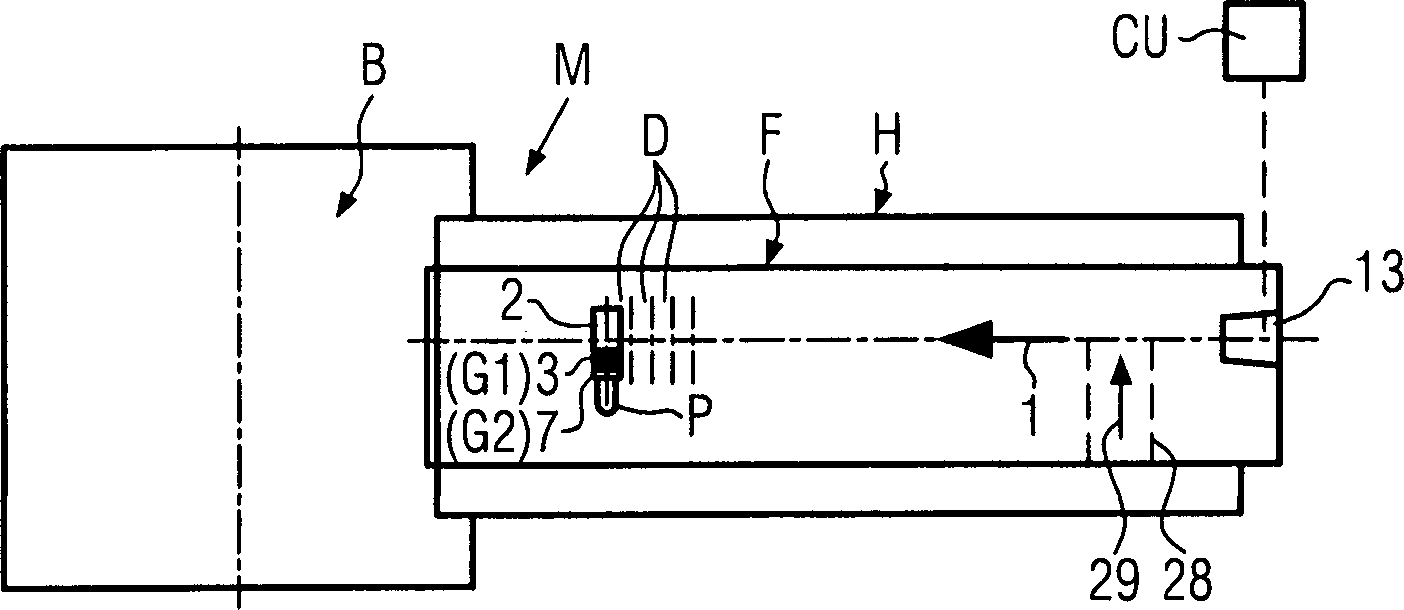
Eine Mündung
Die Mündung
Gemäß
Die Schnittdarstellungen in den
Der Endabschnitt
Eine Schulter
Sicherheitshalber könnten noch weitere zweite Rastvertiefungen
Das Rastelement
Das Sicherungselement S weist einen von außen zugänglichen, beispielsweise verdickten Kopf
Sollte bei einem Wechsel der Steckfuß
Im Betriebsablauf der Maschine, beispielsweise unter betriebsbedingten Erschütterungen und/oder durch das Eigengewicht des Maschinenelements E, könnte sich dann der Endabschnitt
Gemäß
Aufgrund der relativen Dimensionierungen der ersten und zweiten Rastvertiefungen
Eine umgekehrte Struktur der Verrastung
Da das in der Sicherungsposition Y festgelegte Maschinenelement E, beispielsweise der Garniturteil G2, keine ordnungsgemäße Behandlung beispielsweise des Preforms P im Mündungsbereich
Ein ähnliches Schnellwechselsystem, wie anhand der
Das Konzept des Schnellwechselsystems mit der zweiten Sicherung P2 und der Sicherungsposition Y nur geringfügig beabstandet von der Sollposition X kann beispielsweise in der Maschine M gem.
ZITATE ENTHALTEN IN DER BESCHREIBUNG QUOTES INCLUDE IN THE DESCRIPTION
Diese Liste der vom Anmelder aufgeführten Dokumente wurde automatisiert erzeugt und ist ausschließlich zur besseren Information des Lesers aufgenommen. Die Liste ist nicht Bestandteil der deutschen Patent- bzw. Gebrauchsmusteranmeldung. Das DPMA übernimmt keinerlei Haftung für etwaige Fehler oder Auslassungen.This list of the documents listed by the applicant has been generated automatically and is included solely for the better information of the reader. The list is not part of the German patent or utility model application. The DPMA assumes no liability for any errors or omissions.
Zitierte PatentliteraturCited patent literature
- EP 2030759 A [0004] EP 2030759A [0004]
- WO 2009/103435 A [0005] WO 2009/103435 A [0005]
- DE 19803820 A [0006] DE 19803820 A [0006]
- DE 102007037400 A [0049] DE 102007037400 A [0049]
Claims (16)
Priority Applications (4)
| Application Number | Priority Date | Filing Date | Title |
|---|---|---|---|
| DE102010063243A DE102010063243A1 (en) | 2010-12-16 | 2010-12-16 | Quick-change system and operating method of a container-handling machine |
| EP11190355.5A EP2465663B1 (en) | 2010-12-16 | 2011-11-23 | Quick swap system and operating method of a container treatment machine |
| US13/328,205 US8939746B2 (en) | 2010-12-16 | 2011-12-16 | Quick-change system and operating method for a container processing machine |
| CN201110431733.7A CN102529071B (en) | 2010-12-16 | 2011-12-16 | Quick swap system and operating method of a container treatment machine |
Applications Claiming Priority (1)
| Application Number | Priority Date | Filing Date | Title |
|---|---|---|---|
| DE102010063243A DE102010063243A1 (en) | 2010-12-16 | 2010-12-16 | Quick-change system and operating method of a container-handling machine |
Publications (1)
| Publication Number | Publication Date |
|---|---|
| DE102010063243A1 true DE102010063243A1 (en) | 2012-06-21 |
Family
ID=45023725
Family Applications (1)
| Application Number | Title | Priority Date | Filing Date |
|---|---|---|---|
| DE102010063243A Withdrawn DE102010063243A1 (en) | 2010-12-16 | 2010-12-16 | Quick-change system and operating method of a container-handling machine |
Country Status (4)
| Country | Link |
|---|---|
| US (1) | US8939746B2 (en) |
| EP (1) | EP2465663B1 (en) |
| CN (1) | CN102529071B (en) |
| DE (1) | DE102010063243A1 (en) |
Families Citing this family (4)
| Publication number | Priority date | Publication date | Assignee | Title |
|---|---|---|---|---|
| EP3184484B1 (en) * | 2015-12-22 | 2019-10-09 | Sidel Participations, S.A.S. | Filling device for selectively contact or contactless filling an article with a pourable product |
| DE102016001630A1 (en) * | 2016-02-15 | 2017-08-17 | Khs Corpoplast Gmbh | A heating device for the thermal conditioning of preforms intended for blow molding |
| DE102016121685A1 (en) | 2016-11-11 | 2018-05-17 | Krones Ag | Device for heating plastic preforms with shielding plate |
| US10246269B2 (en) * | 2017-03-22 | 2019-04-02 | Fogg Filler Company | Bottle retaining assembly with quick release for a bottle filler |
Citations (7)
| Publication number | Priority date | Publication date | Assignee | Title |
|---|---|---|---|---|
| DE6922331U (en) * | 1968-07-16 | 1969-11-27 | Sig Schweiz Industrieges | PACKAGING CONVERTIBLE TO DIFFERENT BAG SIZE |
| DE19803820A1 (en) | 1998-01-31 | 1999-08-05 | Jagenberg Diana Gmbh | Machine or additional unit for producing folded containers, in particular folding boxes, from blanks |
| US20020036027A1 (en) * | 2000-09-28 | 2002-03-28 | Shikoku Kakoki Co., Ltd. | Liquid metering and filling lifter for containers |
| DE102007037400A1 (en) | 2007-08-08 | 2009-02-12 | Krones Ag | Blowing machine for containers and mandrel holders |
| DE102008033549A1 (en) * | 2007-07-18 | 2009-02-19 | G.D Società per Azioni | Method for controlling an automatic production / packaging machine |
| EP2030759A1 (en) | 2007-08-27 | 2009-03-04 | Krones AG | Blowing machine with fitting holder and such a fitting holder |
| WO2009103435A1 (en) | 2008-02-19 | 2009-08-27 | Khs Ag | System for processing packaging means and method for adjusting such a system correctly for a format |
Family Cites Families (4)
| Publication number | Priority date | Publication date | Assignee | Title |
|---|---|---|---|---|
| CN2834875Y (en) | 2005-10-28 | 2006-11-08 | 蔡佳翰 | Sealing mechanism of bottle blowing machine |
| CN200960722Y (en) | 2006-09-26 | 2007-10-17 | 汪祥建 | Stopping device for plastic bottle blowing machine stretching cylinder |
| CN101722674A (en) * | 2008-10-15 | 2010-06-09 | 扬州捷迈锻压机械有限公司 | Quick replacing system for moulds |
| DE102009023726A1 (en) * | 2009-06-03 | 2010-12-09 | Krones Ag | Blowing machine and automatic change machine |
-
2010
- 2010-12-16 DE DE102010063243A patent/DE102010063243A1/en not_active Withdrawn
-
2011
- 2011-11-23 EP EP11190355.5A patent/EP2465663B1/en active Active
- 2011-12-16 CN CN201110431733.7A patent/CN102529071B/en active Active
- 2011-12-16 US US13/328,205 patent/US8939746B2/en active Active
Patent Citations (7)
| Publication number | Priority date | Publication date | Assignee | Title |
|---|---|---|---|---|
| DE6922331U (en) * | 1968-07-16 | 1969-11-27 | Sig Schweiz Industrieges | PACKAGING CONVERTIBLE TO DIFFERENT BAG SIZE |
| DE19803820A1 (en) | 1998-01-31 | 1999-08-05 | Jagenberg Diana Gmbh | Machine or additional unit for producing folded containers, in particular folding boxes, from blanks |
| US20020036027A1 (en) * | 2000-09-28 | 2002-03-28 | Shikoku Kakoki Co., Ltd. | Liquid metering and filling lifter for containers |
| DE102008033549A1 (en) * | 2007-07-18 | 2009-02-19 | G.D Società per Azioni | Method for controlling an automatic production / packaging machine |
| DE102007037400A1 (en) | 2007-08-08 | 2009-02-12 | Krones Ag | Blowing machine for containers and mandrel holders |
| EP2030759A1 (en) | 2007-08-27 | 2009-03-04 | Krones AG | Blowing machine with fitting holder and such a fitting holder |
| WO2009103435A1 (en) | 2008-02-19 | 2009-08-27 | Khs Ag | System for processing packaging means and method for adjusting such a system correctly for a format |
Also Published As
| Publication number | Publication date |
|---|---|
| EP2465663B1 (en) | 2017-08-09 |
| CN102529071A (en) | 2012-07-04 |
| US8939746B2 (en) | 2015-01-27 |
| CN102529071B (en) | 2015-07-01 |
| EP2465663A2 (en) | 2012-06-20 |
| US20120153524A1 (en) | 2012-06-21 |
| EP2465663A3 (en) | 2016-06-15 |
Similar Documents
| Publication | Publication Date | Title |
|---|---|---|
| EP3284577B1 (en) | Device and method for forming plastic pre-forms into plastic containers with changing device for tools | |
| EP2845714B1 (en) | Method and device for heating plastic pre-forms with simultaneous installation or removal of carrier units and screening elements | |
| DE3613489C2 (en) | ||
| EP2878425B1 (en) | Blow-moulding machine with changing robot and method for the operation of same | |
| EP2878424B1 (en) | Blow-moulding machine with changeable blow-moulding robot with additional processing function | |
| EP2030759B1 (en) | Blowing machine with fitting holder and such a fitting holder | |
| EP2108928B1 (en) | Device and procedure to monitor the operability of a container treatment device | |
| DE102013113074A1 (en) | Blow molding machine with changing robot and gripping device and method for their operation | |
| EP3623791B1 (en) | Device for testing a connection between a tamper-evident ring of a tamper-evident closure provided in a closure cap and a lid base body | |
| WO2014114411A1 (en) | Method for operating a container handling installation and container handling installation | |
| EP2386403B1 (en) | Heating tunnel and handling device for preforms | |
| EP2465663B1 (en) | Quick swap system and operating method of a container treatment machine | |
| DE602004005193T2 (en) | DEVICE FOR PRODUCING CLOSURES | |
| EP3133034A1 (en) | Device and method for feeding products | |
| EP4159408B1 (en) | Device for heating plastic preforms, having a shielding plate | |
| DE202015106885U1 (en) | Vertical packaging machine | |
| EP3138778B1 (en) | Jacket closing machine | |
| EP3190093B1 (en) | Device for producing hollow glass items | |
| EP2657179B1 (en) | Device for closing plastic bottles | |
| WO2019154525A1 (en) | Measurement module for calibrating a container handling device | |
| EP3967472A1 (en) | Method and device for packaging injection molded parts | |
| DE102023113975A1 (en) | Coupling system for glue hoses and method for operating a gluing machine | |
| EP4559828A1 (en) | Method for applying a label to a container | |
| DE102022131014A1 (en) | Industrial robot with safety mechanism for a gripper head | |
| WO2025040273A1 (en) | Container conveying device for conveying containers |
Legal Events
| Date | Code | Title | Description |
|---|---|---|---|
| R163 | Identified publications notified | ||
| R012 | Request for examination validly filed | ||
| R119 | Application deemed withdrawn, or ip right lapsed, due to non-payment of renewal fee |