DE102010041957A1 - Electrode configuration for touch detection and method for detecting a touch of a hand-held device - Google Patents
Electrode configuration for touch detection and method for detecting a touch of a hand-held device Download PDFInfo
- Publication number
- DE102010041957A1 DE102010041957A1 DE102010041957A DE102010041957A DE102010041957A1 DE 102010041957 A1 DE102010041957 A1 DE 102010041957A1 DE 102010041957 A DE102010041957 A DE 102010041957A DE 102010041957 A DE102010041957 A DE 102010041957A DE 102010041957 A1 DE102010041957 A1 DE 102010041957A1
- Authority
- DE
- Germany
- Prior art keywords
- electrode
- handset
- hand
- electrical
- field
- Prior art date
- Legal status (The legal status is an assumption and is not a legal conclusion. Google has not performed a legal analysis and makes no representation as to the accuracy of the status listed.)
- Withdrawn
Links
Images
Classifications
-
- G—PHYSICS
- G06—COMPUTING; CALCULATING OR COUNTING
- G06F—ELECTRIC DIGITAL DATA PROCESSING
- G06F3/00—Input arrangements for transferring data to be processed into a form capable of being handled by the computer; Output arrangements for transferring data from processing unit to output unit, e.g. interface arrangements
- G06F3/01—Input arrangements or combined input and output arrangements for interaction between user and computer
- G06F3/03—Arrangements for converting the position or the displacement of a member into a coded form
- G06F3/041—Digitisers, e.g. for touch screens or touch pads, characterised by the transducing means
- G06F3/044—Digitisers, e.g. for touch screens or touch pads, characterised by the transducing means by capacitive means
-
- G—PHYSICS
- G01—MEASURING; TESTING
- G01R—MEASURING ELECTRIC VARIABLES; MEASURING MAGNETIC VARIABLES
- G01R1/00—Details of instruments or arrangements of the types included in groups G01R5/00 - G01R13/00 and G01R31/00
- G01R1/02—General constructional details
- G01R1/06—Measuring leads; Measuring probes
- G01R1/067—Measuring probes
- G01R1/06766—Input circuits therefor
-
- G—PHYSICS
- G06—COMPUTING; CALCULATING OR COUNTING
- G06F—ELECTRIC DIGITAL DATA PROCESSING
- G06F1/00—Details not covered by groups G06F3/00 - G06F13/00 and G06F21/00
- G06F1/16—Constructional details or arrangements
- G06F1/1613—Constructional details or arrangements for portable computers
- G06F1/1626—Constructional details or arrangements for portable computers with a single-body enclosure integrating a flat display, e.g. Personal Digital Assistants [PDAs]
-
- G—PHYSICS
- G06—COMPUTING; CALCULATING OR COUNTING
- G06F—ELECTRIC DIGITAL DATA PROCESSING
- G06F1/00—Details not covered by groups G06F3/00 - G06F13/00 and G06F21/00
- G06F1/26—Power supply means, e.g. regulation thereof
- G06F1/32—Means for saving power
- G06F1/3203—Power management, i.e. event-based initiation of a power-saving mode
- G06F1/3206—Monitoring of events, devices or parameters that trigger a change in power modality
- G06F1/3231—Monitoring the presence, absence or movement of users
-
- G—PHYSICS
- G06—COMPUTING; CALCULATING OR COUNTING
- G06F—ELECTRIC DIGITAL DATA PROCESSING
- G06F2200/00—Indexing scheme relating to G06F1/04 - G06F1/32
- G06F2200/16—Indexing scheme relating to G06F1/16 - G06F1/18
- G06F2200/163—Indexing scheme relating to constructional details of the computer
- G06F2200/1631—Panel PC, e.g. single housing hosting PC and display panel
-
- H—ELECTRICITY
- H03—ELECTRONIC CIRCUITRY
- H03K—PULSE TECHNIQUE
- H03K17/00—Electronic switching or gating, i.e. not by contact-making and –breaking
- H03K17/94—Electronic switching or gating, i.e. not by contact-making and –breaking characterised by the way in which the control signals are generated
- H03K17/945—Proximity switches
- H03K17/955—Proximity switches using a capacitive detector
-
- Y—GENERAL TAGGING OF NEW TECHNOLOGICAL DEVELOPMENTS; GENERAL TAGGING OF CROSS-SECTIONAL TECHNOLOGIES SPANNING OVER SEVERAL SECTIONS OF THE IPC; TECHNICAL SUBJECTS COVERED BY FORMER USPC CROSS-REFERENCE ART COLLECTIONS [XRACs] AND DIGESTS
- Y02—TECHNOLOGIES OR APPLICATIONS FOR MITIGATION OR ADAPTATION AGAINST CLIMATE CHANGE
- Y02D—CLIMATE CHANGE MITIGATION TECHNOLOGIES IN INFORMATION AND COMMUNICATION TECHNOLOGIES [ICT], I.E. INFORMATION AND COMMUNICATION TECHNOLOGIES AIMING AT THE REDUCTION OF THEIR OWN ENERGY USE
- Y02D10/00—Energy efficient computing, e.g. low power processors, power management or thermal management
Abstract
Bereitgestellt wird einer Elektrodenkonfiguration für eine kapazitive Sensoreinrichtung eines Handgeräts zur Berührungsdetektion einer Bedienperson, wobei die Elektrodenkonfiguration zumindest eine Sendeelektrode, zumindest eine Empfangselektrode und zumindest eine erste Feldmesselektrode umfasst. Die erfindungsgemäße Elektrodenkonfiguration ermöglicht eine Detektion der Lage des Handgerätes relativ zu dem Körper einer Bedienperson ist. Bereitgestellt wird auch Verfahren zur Detektion einer Berührung eines Handgerätes durch eine Bedienperson, wobei das Verfahren angepasst ist die Lage des Handgerätes relativ zu dem Körper einer Bedienperson zu detektieren.An electrode configuration is provided for a capacitive sensor device of a hand-held device for touch detection by an operator, the electrode configuration comprising at least one transmitting electrode, at least one receiving electrode and at least one first field measuring electrode. The electrode configuration according to the invention enables the position of the hand-held device to be detected relative to the body of an operator. A method is also provided for the detection of a touch of a hand-held device by an operator, the method being adapted to detect the position of the hand-held device relative to the body of an operator.
Description
Gegenstand der ErfindungSubject of the invention
Die Erfindung betrifft eine Elektrodenkonfiguration für eine kapazitive Sensoreinrichtung eines Handgeräts zur Berührungsdetektion einer Bedienperson. Die Erfindung betrifft des Weiteren ein Handgerät mit einer erfindungsgemäßen Elektrodenkonfiguration. Ferner betrifft die Erfindung ein Verfahren zur Detektion einer Berührung eines Handgerätes mit einer erfindungsgemäßen Elektrodenkonfiguration durch eine Bedienperson.The invention relates to an electrode configuration for a capacitive sensor device of a hand-held device for detecting the touch of an operator. The invention further relates to a hand-held device with an electrode configuration according to the invention. Furthermore, the invention relates to a method for detecting a touch of a handset with an electrode configuration according to the invention by an operator.
Hintergrund der Erfindung und Stand der TechnikBackground of the invention and prior art
Im Stand der Technik sind Sensoreinrichtungen bekannt, welche an einem Handgerät angeordnet werden können, um eine Annäherung an das Handgerät durch eine Hand zu detektieren. So ist es etwa bekannt, kapazitive Sensoren an einem Handgerät anzuordnen, um aufgrund einer Veränderung der dielektrischen Eigenschaften im Bereich der Sensorelektroden des kapazitiven Sensors auf eine Annäherung einer Hand an die Sensorelektroden zu schließen. Mit derartigen aus dem Stand der Technik bekannten kapazitiven Sensoren kann neben einer Annäherung einer Hand an das Handgerät auch ein Umgreifen des Handgeräts durch die Hand detektiert werden. Damit ist es möglich, das Handgerät zu aktivieren, sobald ein Umgreifen des Handgerätes durch eine Hand detektiert worden ist.In the prior art sensor devices are known, which can be arranged on a handset to detect an approach to the handset by a hand. For example, it is known to arrange capacitive sensors on a hand-held device in order to close due to a change in the dielectric properties in the region of the sensor electrodes of the capacitive sensor on an approach of a hand to the sensor electrodes. With such known from the prior art capacitive sensors in addition to an approach of a hand to the handset and a grasping the handset can be detected by the hand. This makes it possible to activate the handset, as soon as a grasping of the handset has been detected by a hand.
Hierbei ist allerdings nachteilig, dass nicht jedes Umgreifen eines Handgerätes mit der Absicht verbunden ist, das Handgerät tatsächlich zu benutzen. So werden beispielsweise Mobiltelefon oftmals in der Hand getragen, ohne diese unmittelbar benutzen zu wollen. Eine Detektion eines Umgreifens des Mobiltelefons mit dem Verfahren aus dem Stand der Technik würde dieses also in jedem Fall aktivieren. Die Aktivierung des Mobiltelefons führt unter anderem dann zu einem erhöhten Energieverbrauch.However, it is disadvantageous that not every embrace of a handset is connected with the intention to actually use the handset. For example, mobile phones are often carried in the hand, without wanting to use them directly. A detection of a gripping of the mobile phone with the method of the prior art would thus activate this in any case. The activation of the mobile phone leads among other things to an increased energy consumption.
Im Stand der Technik wird durch Einsatz eines Timers versucht, diesen Nachteil zu überwinden. Dabei wird nach der Detektion eines Umgreifens das Mobiltelefon bzw. das Handgerät aktiviert und gleichzeitig ein Timer gestartet. Erreicht der Timer einen vorbestimmten Wert, ohne dass eine Bedienung des Mobiltelefons vorgenommen wurde, wird das Mobiltelefon wieder abgeschaltet. Damit wird der Nachteil des unnötigen Energieverbrauchs allerdings nur teilweise vermieden, weil das Mobiltelefon zunächst aktiviert wird, bevor mit Erreichen eines bestimmten Timerwertes das Mobiltelefon wieder deaktiviert wird.The prior art attempts to overcome this disadvantage by using a timer. In this case, after the detection of a gripping the mobile phone or the handset is activated and simultaneously started a timer. If the timer reaches a predetermined value without an operation of the mobile phone has been made, the mobile phone is switched off again. However, the disadvantage of unnecessary energy consumption is only partially avoided because the mobile phone is first activated before the mobile phone is deactivated again when a certain timer value is reached.
Ferner ist aus dem Stand der Technik bekannt, zusätzlich zu dem kapazitiven Sensor für die Detektion des Umgreifens einen Lagesensor vorzusehen, welcher Informationen darüber liefert, ob sich das Mobiltelefon in einer aufrechten Position befindet, was in der Regel auf eine Benutzung des Mobiltelefons schließen lässt. Nachteilig ist hierbei, dass zwei verschiedene Sensortechnologien zum Einsatz kommen, was zu einem erhöhten Materialaufwand führt. Ferner ist auch durch die Verwendung des zusätzlichen Lagesensors nicht gewährleistet, dass das Mobiltelefon, selbst wenn es in einer aufrechten Position gehalten wird, auch tatsächlich benutzt wird, beispielsweise wenn das Mobiltelefon mit dem Display zur Handfläche hin in der Hand gehalten wird.It is also known from the prior art to provide a position sensor in addition to the capacitive sensor for the detection of gripping, which provides information on whether the mobile phone is in an upright position, which usually suggests a use of the mobile phone. The disadvantage here is that two different sensor technologies are used, which leads to an increased cost of materials. Furthermore, the use of the additional position sensor also does not ensure that the mobile phone is actually used, even when it is held in an upright position, for example, when the mobile phone is held with the display towards the palm of the hand.
Aufgabe der ErfindungObject of the invention
Aufgabe der vorliegenden Erfindung war es daher, Lösungen bereitzustellen, mit welchen die Absicht einer Bedienung eines elektrischen Handgerätes zuverlässiger erkannt werden kann.The object of the present invention was therefore to provide solutions with which the intention of operating an electrical hand-held device can be recognized more reliably.
Erfindungsgemäße LösungInventive solution
Diese Aufgabe wird erfindungsgemäß mit einer Elektrodenkonfiguration für eine kapazitive Sensoreinrichtung eines Handgerätes zur Berührungsdetektion einer Bedienperson, durch ein Handgerät mit einer erfindungsgemäßen Elektrodenkonfiguration sowie ein Verfahren zur Detektion einer Berührung eines Handgerätes nach den unabhängigen Ansprüchen gelöst. Vorteilhafte Ausgestaltungen der Erfindung sind in den jeweiligen abhängigen Ansprüchen angegeben.This object is achieved according to the invention with an electrode configuration for a capacitive sensor device of a hand-held device for detecting the touch of an operator, a hand-held device with an electrode configuration according to the invention and a method for detecting a touch of a hand-held device according to the independent claims. Advantageous embodiments of the invention are specified in the respective dependent claims.
Bereitgestellt wird demnach eine Elektrodenkonfiguration für eine kapazitive Sensoreinrichtung eines Handgeräts zur Berührungsdetektion einer Bedienperson, wobei die Elektrodenkonfiguration umfasst
- – zumindest eine Sendeelektrode,
- – zumindest eine Empfangselektrode, und
- – zumindest eine erste Feldmesselektrode,
- At least one transmitting electrode,
- - At least one receiving electrode, and
- At least a first field sensing electrode,
Die Elektrodenkonfiguration kann ferner zumindest eine zweite Feldmesselektrode umfassen, wobei das erste elektrische Wechselfeld zumindest teilweise in die zumindest eine zweite Feldmesselektrode einkoppelbar ist und wobei das an der zumindest einen zweiten Feldmesselektrode eingekoppelte erste elektrische Wechselfeld indikativ für die Lage des Handgerätes relativ zu dem Körper der Bedienperson ist.The electrode configuration may further include at least one second field sensing electrode, wherein the first alternating electrical field is at least partially coupled into the at least one second field sensing electrode and wherein the first alternating electric field coupled to the at least one second field sensing electrode is indicative of the position of the handset relative to the body of the operator is.
Die zumindest eine erste Feldmesselektrode kann an einer Vorderseite des Handgerätes anordenbar sein und die zumindest eine zweite Feldmesselektrode kann an einer Rückseite des Handgerätes anordenbar sein, wobei eine an der ersten Feldmesselektrode abgegriffene erste elektrische Größe und eine an der zweiten Feldmesselektrode abgegriffene zweite elektrische Größe indikativ für die Lage des Handgerätes relativ zu dem Körper der Bedienperson ist.The at least one first field sensing electrode may be disposable on a front side of the handset and the at least one second field sensing electrode may be disposable on a back side of the handset, indicative of a first electrical quantity sensed at the first field sensing electrode and a second electrical sensing sensed at the second field sensing electrode the position of the handset is relative to the body of the operator.
Die abgegriffene erste elektrische Größe und die abgegriffene zweite elektrische Größe können einer Auswerteeinrichtung, welche mit der zumindest einen ersten Feldmesselektrode und mit der zumindest einen zweiten Feldmesselektrode gekoppelt ist, zuführbar sein, wobei die Auswerteeinrichtung angepasst ist, eine Differenz zwischen der ersten elektrischen Größe und der zweiten elektrischen Größe zu bilden, wobei die Differenz indikativ für die Lage des Handgerätes relativ zu dem Körper der Bedienperson ist.The tapped first electrical variable and the tapped second electrical variable can be fed to an evaluation device, which is coupled to the at least one first field sensing electrode and to the at least one second field sensing electrode, wherein the evaluation device is adapted, a difference between the first electrical variable and the second electrical quantity, wherein the difference is indicative of the position of the handset relative to the body of the operator.
Der Wert der Differenz kann kleiner Null sein, wenn die Rückseite des Handgerätes zur Handfläche einer das Handgerät umgreifenden Hand ausgerichtet ist und der Wert der Differenz kann größer Null sein, wenn die Vorderseite des Handgerätes zur Handfläche einer das Handgerät umgreifenden Hand ausgerichtet ist.The value of the difference may be less than zero when the back of the handset is aligned with the palm of a hand embracing hand and the value of the difference may be greater than zero when the front of the handset is aligned with the palm of a hand embracing the handset.
Die Auswerteeinrichtung kann weiter angepasst sein, zu überprüfen, ob die erste elektrische Größe und die zweite elektrische Größe betragsmäßig oberhalb eines ersten Schwellenwertes liegen, wenn die Differenz zwischen der ersten elektrischen Größe und der zweiten elektrischen Größe betragsmäßig unterhalb eines zweiten Schwellenwertes liegt.The evaluation device can be further adapted to check whether the first electrical variable and the second electrical variable are in absolute value above a first threshold value if the difference between the first electrical variable and the second electrical variable is below a second threshold value.
Ferner kann eine der beiden Feldmesselektroden mit einem zweiten elektrischen Wechselsignal beaufschlagbar sein, zum Erzeugen eines zweiten elektrischen Wechselfeldes, welches an der mit dem zweiten elektrischen Wechselsignal beaufschlagten Feldmesselektrode emittierbar ist und an der jeweils anderen Feldmesselektrode der beiden Feldmesselektroden einkoppelbar ist, wenn die Differenz zwischen der ersten elektrischen Größe und der zweiten elektrischen Größe betragsmäßig unterhalb eines zweiten Schwellenwertes liegt.Furthermore, one of the two field sensing electrodes can be acted upon by a second alternating electrical signal for generating a second alternating electric field which can be emitted at the field measuring electrode subjected to the second alternating electrical signal and can be coupled to the respective other field measuring electrode of the two field measuring electrodes, if the difference between the field measuring electrodes amount of the first electrical variable and the second electrical quantity is below a second threshold value.
Die Elektrodenkonfiguration kann ferner zumindest eine Kompensationselektrode umfassen, welche mit einem dritten elektrischen Wechselsignal beaufschlagbar ist, zum Erzeugen eines an der zumindest einen Kompensationselektrode emittierbaren dritten elektrischen Wechselfeldes, wobei das dritte elektrische Wechselfeld zumindest teilweise in die zumindest eine Empfangselektrode einkoppelbar ist und wobei das an der zumindest einen Empfangselektrode zusammen mit dem eingekoppelten ersten elektrischen Wechselfeld eingekoppelte dritte elektrische Wechselfeld indikativ für das Umgreifen des Handgerätes durch die Hand der Bedienperson ist.The electrode configuration may further comprise at least one compensation electrode, which can be acted upon by a third alternating electrical signal, for generating a third alternating electric field which can be emitted at the at least one compensation electrode, wherein the third alternating electrical field can be coupled at least partially into the at least one receiving electrode and wherein the at the at least one receiving electrode together with the coupled first alternating electric field coupled third alternating electric field indicative of embracing the handset by the hand of the operator.
Vorzugsweise ist das dritte elektrische Wechselsignal phasenverschoben zum ersten elektrischen Wechselsignal ist. Die Amplitude des ersten elektrischen Wechselsignals ist vorzugsweise größer als die Amplitude des dritten elektrischen Wechselsignals.Preferably, the third electrical alternating signal is out of phase with the first electrical alternating signal. The amplitude of the first electrical alternating signal is preferably greater than the amplitude of the third electrical alternating signal.
Die zumindest eine Sendeelektrode und die zumindest eine Empfangselektrode sind vorzugsweise so relativ zueinander an dem Handgerät anordenbar, dass sie bei einem Umgreifen des Handgerätes durch eine Hand von dieser zumindest teilweise überdeckt werden.The at least one transmitting electrode and the at least one receiving electrode are preferably so relative to each other on the handset can be arranged that they are at least partially covered by a hand when embracing the handset by this hand.
Bereitgestellt wird auch ein Handgerät, insbesondere Mobilfunkgerät, mit einer erfindungsgemäßen Elektrodenkonfiguration, wobei
- – die zumindest eine Sendeelektrode an einer ersten Seitenwandung des Handgerätes angeordnet ist,
- – die zumindest eine Empfangselektrode an einer der ersten Seitenwandung gegenüberliegenden zweiten Seitenwandung des Handgerätes angeordnet ist, und
- – die zumindest eine erste Feldmesselektrode an der Vorderseite oder an der Rückseite des Handgerätes angeordnet ist.
- The at least one transmitting electrode is arranged on a first side wall of the hand-held device,
- - The at least one receiving electrode is disposed on one of the first side wall opposite the second side wall of the handset, and
- - The at least one first Feldmesselektrode is arranged on the front or on the back of the handset.
Die zumindest eine erste Feldmesselektrode kann im Bereich des Schwerpunktes des Handgerätes an der Vorderseite oder an der Rückseite des Handgerätes angeordnet sein.The at least one first field sensing electrode can be arranged in the region of the center of gravity of the handheld device at the front or at the rear of the handheld device.
Ferner wird ein Verfahren zur Detektion einer Berührung eines Handgerätes durch eine Bedienperson bereitgestellt, wobei das Verfahren zumindest die folgenden Schritte umfasst:
- – Beaufschlagen zumindest einer Sendeelektrode mit einem ersten elektrischen Wechselsignal, zum Erzeugen eines an der zumindest einen Sendeelektrode emittierbaren ersten elektrischen Wechselfeldes, welches zumindest teilweise in zumindest eine Empfangselektrode und in zumindest eine erste Feldmesselektrode einkoppelbar ist,
- – Auswerten eines an der ersten Feldmesselektrode abgegriffenen ersten elektrischen Signals, welches ein Maß für die kapazitive Kopplung zwischen der zumindest einen Sendeelektrode und der zumindest einen ersten Feldmesselektrode ist,
- – Auswerten eines an der Empfangselektrode abgegriffenen dritten elektrischen Signals, welches ein Maß für die kapazitive Kopplung zwischen der zumindest einen Sendeelektrode und der zumindest einen Empfangselektrode ist, wobei
- – das erste elektrische Signals indikativ für die Lage des Handgerätes relativ zu dem Körper der Bedienperson ist, und
- – das dritte elektrische Signal indikativ für das Umgreifen des Handgerätes durch eine Hand der Bedienperson ist.
- Applying at least one transmitting electrode with a first alternating electrical signal, for generating a first alternating electric field which can be emitted at the at least one transmitting electrode and which can be coupled at least partially into at least one receiving electrode and into at least one first field measuring electrode;
- Evaluating a first electrical signal tapped at the first field sensing electrode, which is a measure of the capacitive coupling between the at least one transmitting electrode and the at least one first field measuring electrode,
- - Evaluating a tapped at the receiving electrode third electrical signal, which is a measure of the capacitive coupling between the at least one transmitting electrode and the at least one receiving electrode, wherein
- The first electrical signal is indicative of the position of the handset relative to the body of the operator, and
- - The third electrical signal is indicative of embracing the handset by a hand of the operator.
Das erste elektrische Wechselfeld kann in zumindest eine zweite Feldmesselektrode einkoppelbar sein, wobei das Verfahren weiter umfasst:
- – Auswerten eines an der zweiten Feldmesselektrode abgegriffenen zweiten elektrischen Signals, und
- – Ermitteln einer Differenz zwischen dem ersten elektrischen Signal und dem zweiten elektrischen Signal, wobei die Differenz indikativ für die Lage des Handgerätes relativ zu dem Körper der Bedienperson ist.
- - Evaluating a tapped at the second field sensing electrode second electrical signal, and
- Determining a difference between the first electrical signal and the second electrical signal, wherein the difference is indicative of the position of the handset relative to the body of the operator.
Das Verfahren kann weiter umfassen:
- – Beaufschlagen zumindest einer Kompensationselektrode mit einem dritten elektrischen Wechselsignal, zum Erzeugen eines an der zumindest einen Kompensationselektrode emittierbaren dritten elektrischen Wechselfeldes, welches zusammen mit dem ersten elektrischen Wechselfeld in die zumindest eine Empfangselektrode einkoppelbar ist.
- - Applying at least one compensation electrode with a third electrical alternating signal, for generating a third alternating electric field which can be emitted at the at least one compensation electrode and which can be coupled into the at least one receiving electrode together with the first alternating electrical field.
Die zumindest eine Empfangselektrode kann in einen Sendemodus umgeschaltet werden, nachdem das Umgreifen des Handgerätes durch die Hand detektiert worden ist, wobei in dem Sendemodus die zumindest eine Empfangselektrode mit einem vierten elektrischen Wechselsignal beaufschlagt wird, um an der zumindest einen Empfangselektrode ein viertes elektrisches Wechselfeld zu emittieren, welches in zumindest eine der Feldmesselektroden einkoppelbar ist. Damit kann die Detektionsgenauigkeit weiter verbessert werden.The at least one receiving electrode can be switched to a transmission mode after hand gripping of the handset has been detected, wherein in the transmission mode the at least one receiving electrode is acted upon by a fourth alternating electrical signal to apply a fourth alternating electric field to the at least one receiving electrode emit, which can be coupled into at least one of the field sensing electrodes. Thus, the detection accuracy can be further improved.
Ferner kann zumindest eine der Feldmesselektroden in einem Sendemodus betrieben werden, in welchem die Feldmesselektrode mit einem elektrischen Wechselsignal beaufschlagt wird, um ein elektrisches Wechselfeld zu emittieren, welches in die andere Feldmesselektrode einkoppelbar ist.Further, at least one of the field sensing electrodes may be operated in a transmitting mode in which the field sensing electrode is applied with an alternating electrical signal to emit an alternating electric field which is injectible into the other field sensing electrode.
Kurzbeschreibung der FigurenBrief description of the figures
Weitere Einzelheiten und Merkmale der Erfindung ergeben sich aus der nachfolgenden Beschreibung in Verbindung mit der Zeichnung. Es zeigt:Further details and features of the invention will become apparent from the following description taken in conjunction with the drawings. It shows:
Detaillierte Beschreibung der ErfindungDetailed description of the invention
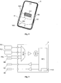
Die Elektroden SE, EE und KE sind jeweils so an den Seitenwandungen des Handgerätes G angeordnet, dass beim Umgreifen des Handgerätes durch eine Hand diese zumindest teilweise durch die Hand überdeckt werden. Die Sendeelektrode SE wird mit einem ersten elektrischen Wechselsignal beaufschlagt, um ein an der Sendeelektrode SE emittiertes erstes elektrisches Wechselfeld WF1 zu erzeugen. Wird das Handgerät G von einer Hand umgriffen, koppelt das an der Sendeelektrode SE emittierte erste elektrische Wechselfeld WF1 über die Hand in die Empfangselektrode EE ein.The electrodes SE, EE and KE are each arranged on the side walls of the hand-held device G so that when the hand-held device is gripped by a hand they are at least partially covered by the hand. The transmitting electrode SE is supplied with a first alternating electrical signal to generate a first alternating electric field WF1 emitted at the transmitting electrode SE. If the handset G is gripped by one hand, the first alternating electric field WF1 emitted at the transmitting electrode SE is coupled via the hand into the receiving electrode EE.
Durch die Anordnung der Elektroden SE bzw. EE an der Seitenwandung des Handgerätes G wird gewährleistet, dass es, wenn das elektrische Handgerät G auf einer (elektrisch leitfähigen) Ablagefläche abgelegt ist, zu keiner Fehldetektion kommt, d. h., dass durch die Ablage des Handgerätes G auf einer Ablagefläche nicht fälschlicherweise ein Umgreifen des Handgerätes detektiert wird. Weil die Elektroden SE und EE an der Seitenwandung des Handgerätes angeordnet sind, koppelt nur ein geringer Teil des an der Sendeelektrode SE emittierten elektrischen Wechselfeldes WF1 über die Ablagefläche in die Empfangselektrode EE ein.The arrangement of the electrodes SE and EE on the side wall of the hand-held device G ensures that, when the electrical hand-held device G is placed on a (electrically conductive) storage surface, there is no misdetection, ie. h., That by the storage of the handset G on a storage surface is not erroneously a grasping of the handset is detected. Because the electrodes SE and EE are arranged on the side wall of the hand-held device, only a small part of the alternating electric field WF1 emitted at the transmitting electrode SE couples into the receiving electrode EE via the depositing surface.
Um die Gefahr einer Fehldetektion noch weiter zu verringern, ist die Kompensationselektrode KE vorgesehen. Die Kompensationselektrode KE wird mit einem dritten elektrischen Wechselsignal beaufschlagt. Das dritte elektrische Wechselsignal ist vorzugsweise phasenverschoben zu dem ersten elektrischen Wechselsignal. Vorzugsweise weist das dritte elektrische Wechselsignal eine Amplitude auf, welche geringer ist, als die Amplitude des ersten elektrischen Wechselsignals. To further reduce the risk of misdetection, the compensation electrode KE is provided. The compensation electrode KE is supplied with a third alternating electrical signal. The third alternating electrical signal is preferably out of phase with the first alternating electrical signal. Preferably, the third electrical alternating signal has an amplitude which is lower than the amplitude of the first electrical alternating signal.
Durch Beaufschlagen der Kompensationselektrode KE mit dem dritten elektrischen Wechselsignal wird bewirkt, dass an der Kompensationselektrode KE ein drittes elektrisches Wechselfeld emittiert wird, welches in die Empfangselektrode EE einkoppelt. Die Kompensationselektrode KE ist vorzugsweise derart relativ zu der Empfangselektrode EE an dem Handgerät G angeordnet, dass das an der Kompensationselektrode KE emittierte dritte elektrische Wechselfeld auch dann in die Empfangselektrode EE einkoppelt, wenn das elektrische Handgerät G nicht von einer Hand umgriffen wird. Ist das Handgerät G auf einer (elektrisch leitfähigen) Ablagefläche abgelegt und koppelt ein geringer Teil des an der Sendeelektrode SE emittierten elektrischen Wechselfeldes über die Ablagefläche in die Empfangselektrode EE ein, wird dieses elektrische Wechselfeld durch das phasenverschobene und vorzugsweise bedampfte von der Kompensationselektrode KE emittierte dritte elektrische Wechselfeld nahezu ausgelöscht. Der Pegelanstieg eines in der Empfangselektrode EE gemessenen elektrischen Stromes, welcher durch das eingekoppelte erste elektrische Wechselfeld und das eingekoppelte dritte elektrische Wechselfeld bewirkt wird, ist dabei so gering, dass eine Fehldetektion eines Umgreifens nahezu vollständig vermieden wird.By applying the compensation electrode KE with the third electrical alternating signal, a third alternating electrical field is emitted at the compensation electrode KE, which couples into the receiving electrode EE. The compensation electrode KE is preferably arranged relative to the receiving electrode EE on the handset G, that the third alternating electric field emitted at the compensation electrode KE also coupled into the receiving electrode EE when the electric handset G is not encompassed by a hand. If the hand-held device G is deposited on an (electrically conductive) storage surface and couples a small part of the alternating electric field emitted at the transmitting electrode SE via the depositing surface into the receiving electrode EE, this alternating electric field is emitted by the phase-shifted and preferably vapor-deposited third electron emitted by the compensation electrode KE alternating electric field almost extinguished. The increase in level of an electrical current measured in the receiving electrode EE, which is caused by the coupled-in first alternating electrical field and the coupled-in third alternating electrical field, is so small that a misdetection of gripping around is almost completely avoided.
Umgreift eine Hand das elektrische Handgerät G, so dass die Hand die Sendeelektrode SE und die Empfangselektrode EE zumindest teilweise überdeckt, wird ein Teil des an der Sendeelektrode SE emittierten ersten elektrischen Wechselfeldes WF1 über die Hand in die Empfangselektrode EE eingekoppelt, wobei sich das über die Hand direkt in die Empfangselektrode EE eingekoppelte erste elektrische Wechselfeld WF1 dem Wirkbereich der Kompensationselektrode KE entzieht. Dies führt zu einem signifikanten Pegelanstieg des an der Empfangselektrode EE gemessenen elektrischen Stromes, welcher indikativ für das Umgreifen des Handgerätes durch die Hand ist.If a hand grips the electrical hand-held device G, so that the hand at least partially covers the transmitting electrode SE and the receiving electrode EE, a part of the first alternating electric field WF1 emitted at the transmitting electrode SE is coupled via the hand into the receiving electrode EE, the signal being transmitted via the Hand directly into the receiving electrode EE coupled first alternating electric field WF1 the effective range of the compensation electrode KE withdraws. This leads to a significant increase in the level of the electrical current measured at the receiving electrode EE, which is indicative of the gripping of the handheld device by the hand.
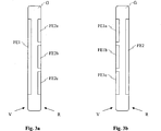
Des Weiteren ist an der Vorderseite des elektrischen Handgerätes G eine erste Feldmesselektrode FE1 angeordnet. An der Rückseite des elektrischen Handgerätes G ist eine zweite Feldmesselektrode FE2 angeordnet. Diese beiden Feldmesselektroden FE1 und FE2 sind dazu vorgesehen, um eine tatsächliche Bedienung des elektrischen Handgerätes zu erkennen.Furthermore, a first field sensing electrode FE1 is arranged on the front side of the electrical hand-held device G. At the back of the electric hand-held device G, a second field sensing electrode FE2 is arranged. These two field sensing electrodes FE1 and FE2 are provided to detect actual operation of the electrical handset.
Das an der Sendeelektrode SE emittierte erste elektrische Wechselfeld WF1 koppelt auch in die erste Feldmesselektrode FE1 und in die zweite Feldmesselektrode FE2 ein. Wird nun das elektrische Handgerät G von einer Hand so umgriffen, dass die Rückseite des Handgerätes G der Handfläche zugewandt ist, ist die kapazitive Koppelung zwischen der Sendeelektrode SE und der zweiten Feldmesselektrode FE2 größer als die kapazitive Koppelung zwischen der Sendeelektrode SE und der ersten Feldmesselektrode FE1. Dies führt dazu, dass der elektrische Strom in der zweiten Feldmesselektrode FE2 wesentlich größer ist, als der elektrische Strom in der ersten Feldmesselektrode FE1. Wird ein Umgreifen des Handgerätes detektiert, wie vorstehend beschrieben, und ist der elektrische Strom in der zweiten Feldmesselektrode FE2 größer als der elektrische Strom in der ersten Feldmesselektrode FE1, kann daraus geschlossen werden, dass eine Bedienintention des Benutzers vorliegt.The first alternating electric field WF1 emitted at the transmitting electrode SE also couples into the first field measuring electrode FE1 and into the second field measuring electrode FE2. If now the electric hand-held device G is grasped by one hand so that the back of the hand-held device G faces the palm, the capacitive coupling between the transmitting electrode SE and the second field sensing electrode FE2 is greater than the capacitive coupling between the transmitting electrode SE and the first field sensing electrode FE1 , This results in that the electric current in the second field sensing electrode FE2 is substantially greater than the electric current in the first field sensing electrode FE1. If a grasping of the handset is detected, as described above, and the electric current in the second field sensing electrode FE2 is greater than the electric current in the first field sensing electrode FE1, it can be concluded that an operating intention of the user exists.
Ist hingegen der elektrische Strom in der ersten Feldmesselektrode FE1 größer als der elektrische Strom in der zweiten Feldmesselektrode FE2, kann daraus geschlossen werden, dass die Vorderseite des elektrischen Handgerätes G der Handfläche einer das Handgerät G umgreifenden Hand zugewandt ist. Dieser Situation kann eindeutig eine Nichtbedienung des elektrischen Handgerätes zugeordnet werden.If, however, the electrical current in the first field sensing electrode FE1 is greater than the electrical current in the second field sensing electrode FE2, it can be concluded that the front side of the electrical handset G faces the palm of a hand surrounding the handset G. This situation can clearly be attributed to a non-operation of the electrical handset.
Die Auswertung kann beispielsweise durch Vergleich der elektrischen Ströme in den Feldmesselektroden FE1 und FE2 vorgenommen werden. Alternativ kann auch eine Differenzbildung der elektrischen Ströme in der ersten Feldmesselektrode FE1 und in der zweiten Feldmesselektrode FE2 durchgeführt werden. Ist die Differenz der beiden Ströme in den Feldmesselektroden FE1 und FE2 kleiner Null, ist die Rückseite des Handgerätes G der Handfläche zugewandt, während die Vorderseite des Handgerätes G der Handfläche zugewandt ist, wenn die Differenz der Ströme größer Null ist.The evaluation can be carried out, for example, by comparing the electrical currents in the field sensing electrodes FE1 and FE2. Alternatively, it is also possible to carry out a subtraction of the electrical currents in the first field measuring electrode FE1 and in the second field measuring electrode FE2. If the difference of the two currents in the field sensing electrodes FE1 and FE2 is less than zero, the back of the handset G faces the palm while the front of the handset G faces the palm when the difference in currents is greater than zero.
Vorzugsweise werden die Ströme in den Feldmesselektroden FE1 und FE2 bzw. die Differenz dieser Ströme erst dann ermittelt, wenn ein Umgreifen des elektrischen Handgerätes G detektiert worden ist. Damit wird vermieden, dass eine Fehldetektion einer Bedienintention detektiert wird, was beispielsweise dann der Fall sein könnte, wenn das elektrische Handgerät G mit der Rückseite auf einer elektrisch leitfähigen Oberfläche abgelegt wird. In diesem Fall wäre der elektrische Strom in der zweiten Feldmesselektrode FE2 wesentlich größer als der elektrische Strom in der ersten Feldmesselektrode FE1.Preferably, the currents in the field sensing electrodes FE1 and FE2 or the difference of these currents are only determined when a gripping of the electrical hand-held device G has been detected. This avoids that a misdetection of an operating intention is detected, which could be the case, for example, when the electrical hand-held device G is placed on an electrically conductive surface with the rear side. In this case, the electric current in the second field sensing electrode FE2 would be much larger than the electric current in the first field sensing electrode FE1.
Das bedeutet, dass die Feldmesselektroden FE1 und FE2 bzw. die Auswertung der elektrischen Ströme an den Feldmesselektroden FE1 und FE2 erst dann aktiviert werden, wenn ein Umgreifen des elektrischen Handgerätes detektiert worden ist. This means that the field sensing electrodes FE1 and FE2 or the evaluation of the electrical currents at the field sensing electrodes FE1 and FE2 are activated only when encircling the electrical handset has been detected.
Um die Detektionsgenauigkeit zur Detektion der Bedienintention weiter zu erhöhen, können die für die Detektion des Umgreifens vorgesehenen Elektroden SE, EE und KE in einem zweiten Betriebsmodus betrieben werden. In dem zweiten Betriebsmodus kann die Empfangselektrode EE als zusätzliche Sendeelektrode betrieben werden, an welcher ebenfalls das erste elektrische Wechselfeld WF1 emittierbar ist. Dadurch wird an beiden Seiten des elektrischen Handgerätes das erste elektrische Wechselfeld WF1 emittiert, welches über die Hand in die Feldmesselektroden FE1 bzw. FE2 einkoppelt. Damit wird vermieden, dass bei ungünstigem Umgreifen des Handgerätes durch die Hand keine bzw. nur eine sehr geringe Koppelung zwischen der Sendeelektrode SE und den Feldmesselektroden FE1 bzw. FE2 vorhanden ist.In order to further increase the detection accuracy for the detection of the operating intention, the electrodes SE, EE and KE provided for the detection of the encompassing can be operated in a second operating mode. In the second operating mode, the receiving electrode EE can be operated as an additional transmitting electrode on which the first alternating electric field WF1 can likewise be emitted. As a result, the first alternating electric field WF1 is emitted on both sides of the electrical hand-held device, which feeds via the hand into the field measuring electrodes FE1 or FE2. This avoids that in case of unfavorable embrace of the handset by hand no or only a very small coupling between the transmitting electrode SE and the field sensing electrodes FE1 and FE2 is present.
In einer Ausgestaltung der Erfindung ist es ausreichend, lediglich eine der beiden Feldmesselektroden FE1 bzw. FE2 vorzusehen. Beispielsweise kann es ausreichend sein, lediglich die an der Vorderseite des elektrischen Handgerätes angeordnete erste Feldmesselektrode FE1 vorzusehen. Erreicht der an der ersten Feldmesselektrode FE1 gemessene elektrische Strom einen vorbestimmten Schwellenwert, kann daraus geschlossen werden, dass das elektrische Handgerät G so von der Hand umgriffen wird, dass die Vorderseite des Handgerätes G der Handfläche zugewandt ist.In one embodiment of the invention, it is sufficient to provide only one of the two field sensing electrodes FE1 and FE2. For example, it may be sufficient to provide only the first field sensing electrode FE1 arranged on the front side of the electrical hand-held device. If the electrical current measured at the first field sensing electrode FE1 reaches a predetermined threshold value, it can be concluded that the handheld electrical appliance G is gripped by the hand so that the front side of the handheld device G faces the palm of the hand.
Im umgekehrten Fall, wenn nur die zweite Feldmesselektrode FE2 an der Rückseite des Handgerätes G vorgesehen ist, kann bei Überschreiten eines vorbestimmten Schwellenwertes des an der zweiten Feldmesselektrode FE2 gemessenen elektrischen Stromes geschlossen werden, dass das elektrische Handgerät G so von der Hand umgriffen wird, dass die Rückseite der Handfläche zugewandt ist.In the opposite case, if only the second field sensing electrode FE2 is provided on the rear side of the handset G, it can be concluded, when a predetermined threshold value of the electric current measured at the second field sensing electrode FE2 is reached, that the handheld electric device G is encompassed by the hand facing the back of the palm.
Wird das elektrische Handgerät, etwa ein Mobiltelefon, zwischen einer Schulter und dem Kopf eingeklemmt, kann es vorkommen, dass die kapazitive Koppelung zwischen der Sendeelektrode SE und der ersten Feldmesselektrode FE1 nahezu identisch zur kapazitiven Koppelung zwischen der Sendeelektrode SE und der zweiten Feldmesselektrode FE2 ist. In diesem Fall würde die Differenz der in den Feldmesselektroden FE1 und FE2 gemessenen elektrischen Ströme nahezu Null sein, so dass ein Vergleich der in den Feldmesselektroden FE1 und FE2 gemessenen elektrischen Ströme bzw. eine Differenzbildung dieser elektrischen Ströme nicht zum gewünschten Ergebnis führen würde. Um auch diesen Fall sicher zu erkennen, ist es vorteilhaft, zusätzlich zu dem Vergleich der elektrischen Ströme bzw. zur Differenzbildung zusätzlich auch die Absolutwerte der elektrischen Ströme an den Feldmesselektroden FE1 und FE2 zu bestimmen. Übersteigen die in den Feldmesselektroden FE1 und FE2 gemessenen Ströme jeweils einen vorbestimmten Schwellenwert und wurde zuvor ein Umgreifen des elektrischen Handgerätes detektiert, kann daraus geschlossen werden, dass das elektrische Handgerät sowohl an der Rückseite als auch an der Vorderseite von dem Körper der Bedienperson umgeben ist, was beispielsweise beim Einklemmen des Handgerätes G zwischen Schulter und Kopf der Fall ist.If the electrical hand-held device, for example a mobile telephone, is clamped between a shoulder and the head, it can happen that the capacitive coupling between the transmitting electrode SE and the first field measuring electrode FE1 is almost identical to the capacitive coupling between the transmitting electrode SE and the second field measuring electrode FE2. In this case, the difference of the electrical currents measured in the field sensing electrodes FE1 and FE2 would be almost zero, so that a comparison of the measured in the field sensing electrodes FE1 and FE2 electrical currents or a difference of these electrical currents would not lead to the desired result. In order to reliably detect this case as well, it is advantageous, in addition to the comparison of the electrical currents or for subtraction, to additionally determine the absolute values of the electric currents at the field sensing electrodes FE1 and FE2. If the currents measured in the field measuring electrodes FE1 and FE2 each exceed a predetermined threshold value and if a gripping of the electrical handset has previously been detected, it can be concluded that the electrical handset is surrounded by the body of the operator at both the back and the front, which is the case, for example, when clamping the handset G between the shoulder and the head.
Übersteigen die in den Feldmesselektroden gemessenen elektrischen Ströme diesen vorbestimmten Schwellenwert nicht, nachdem ein Umgreifen des Handgerätes detektiert worden ist, kann davon ausgegangen werden, dass keine Intention zur Benutzung des Handgerätes vorliegt.If the electrical currents measured in the field sensing electrodes do not exceed this predetermined threshold value after detecting the encircling of the handset, it can be assumed that there is no intention to use the handheld device.
Die Empfangselektrode EE sowie die Feldmesselektroden FE1 und FE2 sind in dem in
Die Auswerteeinrichtung A stellt an einem Ausgang ein Detektionssignal DS zur Verfügung, welches Informationen über die Lage des Handgerätes relativ zur Handfläche enthält. Die Auswerteeinrichtung A kann beispielsweise als ASIC implementiert werden. Alternativ kann die Auswerteeinrichtung A auch in einem Mikrokontroller, etwa eines Mobiltelefons, integriert sein. The evaluation device A provides at a output a detection signal DS, which contains information about the position of the handset relative to the palm. The evaluation device A can be implemented, for example, as an ASIC. Alternatively, the evaluation device A can also be integrated in a microcontroller, for example a mobile telephone.
Ebenso können an der Vorderseite V und der Rückseite R jeweils mehrere Feldmesselektroden angeordnet werden.Likewise, a plurality of field sensing electrodes can be arranged on the front side V and the rear side R, respectively.
Die Feldmesselektroden können auch in einem Betriebsmodus betrieben werden, in welchem zumindest eine der Feldmesselektroden als Sendeelektrode verwendet wird. Beispielsweise kann die an der Vorderseite des Handgerätes G angeordnete erste Feldmesselektrode FE1 als Sendeelektrode betrieben werden. Die als Sendelektrode betriebene Feldmesselektrode, etwa die erste Feldmesselektrode FE1, wird mit einem zweiten elektrischen Wechselsignal beaufschlagt, um ein elektrisches Wechselfeld zu erzeugen, welches an der als Sendelektrode betriebenen Feldmesselektrode emittiert wird. Das emittierte elektrische Wechselfeld ist in die andere Feldmesselektrode, etwa in die an der Rückseite des Handgerätes G angeordnete zweite Feldmesselektrode FE2 einkoppelbar.The field sensing electrodes may also be operated in an operating mode in which at least one of the field sensing electrodes is used as the transmitting electrode. For example, the first field sensing electrode FE1 arranged on the front side of the handheld device G can be operated as a transmitting electrode. The field sensing electrode, which is operated as the transmitting electrode, for example the first field sensing electrode FE1, is supplied with a second alternating electrical signal in order to generate an alternating electric field, which is emitted at the field sensing electrode operated as a transmitting electrode. The emitted alternating electric field can be coupled into the other field measuring electrode, for example into the second field measuring electrode FE2 arranged on the rear side of the handheld device G.
Nach der Detektion eines Umgreifens des Handgerätes G durch eine Hand werden die an den Feldmesselektroden abgegriffenen elektrischen Signale erfindungsgemäß ausgewertet, um die Lage des Handgerätes G relativ zu dem Körper der Bedienperson zu ermitteln.After detecting a gripping of the hand-held device G by a hand, the electrical signals picked up at the field measuring electrodes are evaluated according to the invention in order to determine the position of the hand-held device G relative to the body of the operator.
Wird das elektrische Handgerät G während der Benutzung zwischen einer Schulter und dem Kopf der Bedienperson eingeklemmt, kann dies dazu führen, dass die kapazitive Koppelung zwischen der Sendeelektrode SE und der Empfangselektrode EE unter einen vorbestimmten Schwellenwert sinkt, welcher indikativ für ein Nicht-Umgreifen des Handgerätes G ist. Um dennoch ermitteln zu können, ob das Handgerät G weiterhin benutzt wird, wird nach dem Unterschreiten des Schwellenwertes eine der Feldmesselektroden als Sendeelektrode betrieben. Beispielsweise wird die erste Feldmesselektrode FE1 als Sendeelektrode betrieben. Ist das elektrische Handgerät G zwischen einer Schulter und dem Kopf der Bedienperson eingeklemmt, koppelt ein Teil des an der ersten Feldmesselektrode FE1 emittierten elektrischen Wechselfeldes über den Körper der Bedienperson in die zweite Feldmesselektrode FE2 ein.If the electrical handset G is pinched between a shoulder and the operator's head during use, this may cause the capacitive coupling between the transmitting electrode SE and the receiving electrode EE to fall below a predetermined threshold indicative of non-encircling the handset G is. In order to still be able to determine whether the handset G is still being used, one of the field sensing electrodes is operated as a transmitting electrode after falling below the threshold value. For example, the first field sensing electrode FE1 is operated as a transmitting electrode. If the electrical hand-held device G is clamped between a shoulder and the head of the operator, a part of the alternating electric field emitted at the first field sensing electrode FE1 couples into the second field sensing electrode FE2 via the body of the operator.
Überschreitet der an der zweiten Feldmesselektrode FE2 gemessene elektrische Strom einen vorbestimmten Schwellenwert, kann davon ausgegangen werden, dass sich das Handgerät G weiterhin in Benutzung befindet, obwohl es nicht mehr durch eine Hand umgriffen wird.If the electrical current measured at the second field sensing electrode FE2 exceeds a predetermined threshold value, it can be assumed that the handheld device G is still in use, although it is no longer encompassed by a hand.
Liegt der an der zweiten Feldmesselektrode FE2 gemessene elektrische Strom unterhalb des vorbestimmten Schwellenwertes, kann davon ausgegangen werden, dass sich das Handgerät G nicht mehr in Benutzung befindet. Das Handgerät G kann dann beispielsweise in einen Ruhemodus versetzt werden.If the electrical current measured at the second field sensing electrode FE2 is below the predetermined threshold value, it can be assumed that the handheld device G is no longer in use. The handset G can then be put into a sleep mode, for example.
Ebenso kann die zweite Feldmesselektrode FE2 als Sendeelektrode betrieben werden.Likewise, the second field sensing electrode FE2 can be operated as a transmitting electrode.
Vorstehend ist ein Mobiltelefon stellvertretend für ein elektrisches Handgerät G beschrieben worden. Ein Handgerät, welches mit einer Sensoreinrichtung mit der erfindungsgemäßen Elektrodenkonfiguration ausgestattet werden kann, kann auch eine Computermaus, eine Gerätefernbedienung, eine Digitalkamera, ein Game-Controller, ein mobiler Kleincomputer (PDA), ein Smartphone oder dergleichen sein.Above, a mobile phone representative of a hand-held electric device G has been described. A handheld device that can be equipped with a sensor device with the electrode configuration according to the invention can also be a computer mouse, a device remote control, a digital camera, a game controller, a mobile small computer (PDA), a smartphone or the like.
Claims (16)
Priority Applications (7)
| Application Number | Priority Date | Filing Date | Title |
|---|---|---|---|
| DE102010041957A DE102010041957A1 (en) | 2010-10-04 | 2010-10-04 | Electrode configuration for touch detection and method for detecting a touch of a hand-held device |
| EP11764194.4A EP2625583A1 (en) | 2010-10-04 | 2011-10-04 | Electrode configuration, hand-held device as well as method for the detection of a touch of a hand-held device |
| CN201180048449XA CN103154848A (en) | 2010-10-04 | 2011-10-04 | Electrode configuration, hand-held device as well as method for the detection of a touch of a hand-held device |
| KR1020137010995A KR20130126904A (en) | 2010-10-04 | 2011-10-04 | Electrode configuration, hand-held device as well as method for the detection of a touch of a hand-held device |
| US13/877,542 US20140218054A1 (en) | 2010-10-04 | 2011-10-04 | Electrode Configuration, Hand-Held Device as Well as Method for the Detection of a Touch of a Hand-Held Device |
| PCT/EP2011/067283 WO2012045724A1 (en) | 2010-10-04 | 2011-10-04 | Electrode configuration, hand-held device as well as method for the detection of a touch of a hand-held device |
| JP2013530765A JP5932805B2 (en) | 2010-10-04 | 2011-10-04 | Electrode configuration, portable device, and method for touch detection of a portable device |
Applications Claiming Priority (1)
| Application Number | Priority Date | Filing Date | Title |
|---|---|---|---|
| DE102010041957A DE102010041957A1 (en) | 2010-10-04 | 2010-10-04 | Electrode configuration for touch detection and method for detecting a touch of a hand-held device |
Publications (1)
| Publication Number | Publication Date |
|---|---|
| DE102010041957A1 true DE102010041957A1 (en) | 2012-04-05 |
Family
ID=44735935
Family Applications (1)
| Application Number | Title | Priority Date | Filing Date |
|---|---|---|---|
| DE102010041957A Withdrawn DE102010041957A1 (en) | 2010-10-04 | 2010-10-04 | Electrode configuration for touch detection and method for detecting a touch of a hand-held device |
Country Status (7)
| Country | Link |
|---|---|
| US (1) | US20140218054A1 (en) |
| EP (1) | EP2625583A1 (en) |
| JP (1) | JP5932805B2 (en) |
| KR (1) | KR20130126904A (en) |
| CN (1) | CN103154848A (en) |
| DE (1) | DE102010041957A1 (en) |
| WO (1) | WO2012045724A1 (en) |
Cited By (2)
| Publication number | Priority date | Publication date | Assignee | Title |
|---|---|---|---|---|
| EP2695576A1 (en) * | 2012-08-07 | 2014-02-12 | Peter Von Buenger | Electrode terminal for bio resonance therapy and diagnosis |
| EP3758230A1 (en) * | 2019-06-28 | 2020-12-30 | Robert Bosch GmbH | Sensor device with capacitive sensor |
Families Citing this family (4)
| Publication number | Priority date | Publication date | Assignee | Title |
|---|---|---|---|---|
| DE102009057933B3 (en) * | 2009-12-11 | 2011-02-24 | Ident Technology Ag | Sensor device for detecting approach and touch of e.g. hand held device by hand, has electrode structure including transmission, compensation and receiving electrodes, where electrical field is received in receiving electrode |
| US9426747B2 (en) * | 2013-03-12 | 2016-08-23 | Qualcomm Incorporated | Hands-off detection and deactivation for handheld user devices |
| KR102242529B1 (en) * | 2014-10-07 | 2021-04-20 | 엘지디스플레이 주식회사 | Stylus pen and display device using the same |
| CN109491501B (en) * | 2018-11-07 | 2022-05-20 | Oppo广东移动通信有限公司 | Electronic device use control method and device, electronic device and storage medium |
Citations (2)
| Publication number | Priority date | Publication date | Assignee | Title |
|---|---|---|---|---|
| WO2009130165A2 (en) * | 2008-04-25 | 2009-10-29 | Ident Technology Ag | Electrode system for proximity detection and hand-held device with electrode system |
| WO2010023257A1 (en) * | 2008-08-29 | 2010-03-04 | Continental Automotive Gmbh | Device and method for recognizing a position change of vehicle occupants |
Family Cites Families (14)
| Publication number | Priority date | Publication date | Assignee | Title |
|---|---|---|---|---|
| US6281888B1 (en) * | 1999-01-07 | 2001-08-28 | International Business Machines Corporation | Pen input device using electrostatic coupling |
| US6859141B1 (en) * | 1999-12-08 | 2005-02-22 | Nortel Networks Limited | Electric field proximity detector for floating and grounded targets |
| US6542436B1 (en) * | 2000-06-30 | 2003-04-01 | Nokia Corporation | Acoustical proximity detection for mobile terminals and other devices |
| US6829400B2 (en) * | 2001-03-26 | 2004-12-07 | Olympus Corporation | Optical path switching apparatus |
| JP2004259107A (en) * | 2003-02-27 | 2004-09-16 | Mitsubishi Electric Corp | Personal digital assistant |
| DE202006010813U1 (en) * | 2006-07-13 | 2007-11-22 | Brose Fahrzeugteile Gmbh & Co. Kommanditgesellschaft, Coburg | Pinch sensor and evaluation circuit |
| JP4232836B2 (en) * | 2007-03-20 | 2009-03-04 | 株式会社豊田中央研究所 | Mobile radio system |
| US8031175B2 (en) * | 2008-04-21 | 2011-10-04 | Panasonic Corporation | Touch sensitive remote control system that detects hand size characteristics of user and adapts mapping to screen display |
| JP2009213126A (en) * | 2008-02-08 | 2009-09-17 | Rohm Co Ltd | Remote control apparatus and electronic device using electrostatic sensor, and control method of switch |
| DE102008020819A1 (en) * | 2008-04-25 | 2009-10-29 | Ident Technology Ag | Wireless computer mouse for use in e.g. computing applications, has tapping circuit generating electrode signals, where electrode signals are supplied to signal control unit designed as microcontroller unit |
| JP2010154090A (en) * | 2008-12-24 | 2010-07-08 | Toshiba Corp | Mobile terminal |
| DE102009060995B4 (en) | 2009-04-07 | 2015-02-12 | Ident Technology Ag | Measuring electrode arrangement for improved proximity detection |
| EP2294695B1 (en) * | 2009-04-07 | 2016-04-06 | Microchip Technology Germany GmbH | Sensor device and method for grip and proximity detection |
| US8954099B2 (en) * | 2010-06-16 | 2015-02-10 | Qualcomm Incorporated | Layout design of proximity sensors to enable shortcuts |
-
2010
- 2010-10-04 DE DE102010041957A patent/DE102010041957A1/en not_active Withdrawn
-
2011
- 2011-10-04 EP EP11764194.4A patent/EP2625583A1/en not_active Withdrawn
- 2011-10-04 CN CN201180048449XA patent/CN103154848A/en active Pending
- 2011-10-04 US US13/877,542 patent/US20140218054A1/en not_active Abandoned
- 2011-10-04 KR KR1020137010995A patent/KR20130126904A/en not_active Application Discontinuation
- 2011-10-04 WO PCT/EP2011/067283 patent/WO2012045724A1/en active Application Filing
- 2011-10-04 JP JP2013530765A patent/JP5932805B2/en not_active Expired - Fee Related
Patent Citations (2)
| Publication number | Priority date | Publication date | Assignee | Title |
|---|---|---|---|---|
| WO2009130165A2 (en) * | 2008-04-25 | 2009-10-29 | Ident Technology Ag | Electrode system for proximity detection and hand-held device with electrode system |
| WO2010023257A1 (en) * | 2008-08-29 | 2010-03-04 | Continental Automotive Gmbh | Device and method for recognizing a position change of vehicle occupants |
Cited By (3)
| Publication number | Priority date | Publication date | Assignee | Title |
|---|---|---|---|---|
| EP2695576A1 (en) * | 2012-08-07 | 2014-02-12 | Peter Von Buenger | Electrode terminal for bio resonance therapy and diagnosis |
| EP3758230A1 (en) * | 2019-06-28 | 2020-12-30 | Robert Bosch GmbH | Sensor device with capacitive sensor |
| US11525704B2 (en) | 2019-06-28 | 2022-12-13 | Robert Bosch Gmbh | Sensor device with capacitive sensor |
Also Published As
| Publication number | Publication date |
|---|---|
| JP5932805B2 (en) | 2016-06-08 |
| WO2012045724A1 (en) | 2012-04-12 |
| US20140218054A1 (en) | 2014-08-07 |
| JP2013543690A (en) | 2013-12-05 |
| KR20130126904A (en) | 2013-11-21 |
| CN103154848A (en) | 2013-06-12 |
| EP2625583A1 (en) | 2013-08-14 |
Similar Documents
| Publication | Publication Date | Title |
|---|---|---|
| DE102009057933B3 (en) | Sensor device for detecting approach and touch of e.g. hand held device by hand, has electrode structure including transmission, compensation and receiving electrodes, where electrical field is received in receiving electrode | |
| DE102009057935B4 (en) | Device and method for detecting gripping of a handheld device by a hand | |
| DE102010041957A1 (en) | Electrode configuration for touch detection and method for detecting a touch of a hand-held device | |
| DE102009057439B4 (en) | Device and method for error-free capacitive measured value acquisition | |
| DE102011006079A1 (en) | Measuring device and method for approach detection | |
| DE102011078534B4 (en) | Evaluation method and evaluation device for a capacitive touch sensor | |
| DE102011078077A1 (en) | Printed circuit board with electrode configuration of a capacitive sensor | |
| EP3746747B1 (en) | Capacitive measuring system | |
| DE102011054415A1 (en) | Method for adjusting the sensitivity of a sensor system | |
| WO2011138081A1 (en) | Detection of a dielectric object | |
| DE102010030959A1 (en) | Sensor device and method for detecting a gripping of a hand-held device and a hand-held device | |
| DE102011078369B4 (en) | Capacitive sensor device and method for calibrating a capacitive sensor device | |
| DE102009057931B4 (en) | Circuit arrangement for a capacitive sensor element. | |
| DE102011002603B4 (en) | Capacitive sensor device and method for operating a capacitive sensor device | |
| EP3060945A1 (en) | Positioning device | |
| WO2016041726A1 (en) | Device and method for monitoring a process variable of a medium | |
| DE102011002446A1 (en) | Sensor device and method for capacitive proximity detection | |
| DE102018113253A1 (en) | arrangement | |
| DE102009061064B4 (en) | Detection device for an electrical hand-held device and hand-held device with a detection device | |
| DE102010012961B4 (en) | Sensor device and method for approach and touch detection | |
| DE102011006743A1 (en) | Detection method for sensing gripping of hand-held device involves operating sensor device in first and second operating modes to detect gripping of hand-held device once amount of electrical signal satisfies predetermined conditions | |
| DE102012222152A1 (en) | Household appliance, particularly cooking appliance, such as baking oven, has door and door detection device for detecting door state of door, where door detection device comprises capacitive sensor, whose moving electrode is door | |
| EP3035366B1 (en) | Ft-icr mass spectrometer with icr measuring cell with a duplexer | |
| DE102009057960A1 (en) | Sensor device for detection of gripping of e.g. electrical hand-held device, by hand, has evaluation device deflecting gripping of hand-held device by hand based on detected capacitance between sensor electrode and mass potential | |
| EP3457569B1 (en) | Evaluation arrangement for a capacitive sensor device |
Legal Events
| Date | Code | Title | Description |
|---|---|---|---|
| R016 | Response to examination communication | ||
| R081 | Change of applicant/patentee |
Owner name: MICROCHIP TECHNOLOGY GERMANY GMBH, DE Free format text: FORMER OWNER: IDENT TECHNOLOGY AG, 82234 WESSLING, DE |
|
| R082 | Change of representative |
Representative=s name: BETTINGER SCHNEIDER SCHRAMM PATENT- UND RECHTSANWA Representative=s name: BETTINGER SCHNEIDER SCHRAMM PATENT- UND RECHTS, DE Representative=s name: 2S-IP SCHRAMM SCHNEIDER PATENTANWAELTE - RECHT, DE |
|
| R016 | Response to examination communication | ||
| R016 | Response to examination communication | ||
| R082 | Change of representative |
Representative=s name: 2S-IP SCHRAMM SCHNEIDER PATENTANWAELTE - RECHT, DE |
|
| R016 | Response to examination communication | ||
| R081 | Change of applicant/patentee |
Owner name: MICROCHIP TECHNOLOGY GERMANY GMBH, DE Free format text: FORMER OWNER: IDENT TECHNOLOGY AG, 82205 GILCHING, DE |
|
| R082 | Change of representative |
Representative=s name: 2S-IP SCHRAMM SCHNEIDER BERTAGNOLL PATENT- UND, DE Representative=s name: 2S-IP SCHRAMM SCHNEIDER PATENTANWAELTE - RECHT, DE |
|
| R119 | Application deemed withdrawn, or ip right lapsed, due to non-payment of renewal fee |