Hintergrund der ErfindungBackground of the invention
Der
hierin offengelegte Erfindungsgegenstand betrifft Abstandssteuerungstechniken,
und insbesondere ein System zum Anpassen des Abstandes zwischen
einer stationären
Komponente und einer Rotationskomponente einer Rotationsmaschine.Of the
Subject matter disclosed herein relates to pitch control techniques,
and in particular, a system for adjusting the distance between
a stationary one
Component and a rotation component of a rotary machine.
In
bestimmten Anwendungen kann ein Abstand zwischen Komponenten vorliegen,
die sich in Bezug zueinander bewegen. Beispielsweise kann ein Abstand
zwischen rotierenden und stationären
Komponenten in einer Rotationsmaschine wie z. B. einem Verdichter,
einer Turbine oder dergleichen vorliegen. Der Abstand kann während des
Betriebs der Rotationsmaschine aufgrund von Temperaturänderungen oder
anderen Faktoren zunehmen oder abnehmen. Wie man erkennen kann,
kann ein kleinerer Abstand Leistung und Wirkungsgrad in einem Verdichter
oder einer Turbine verbessern, da weniger Fluid zwischen Laufschaufeln
und einem umgebenden Deckmantel austritt. Ein kleinerer Abstand
erhöht
jedoch auch die Möglichkeit
des Auftretens eines Reibzustands. Die Betriebsbedingungen beeinflussen
ebenfalls die Möglichkeit
eines Reibzustandsauftritts. Beispielsweise kann die Möglichkeit
des Auftretens eines Reibungszustands während Übergangszuständen zunehmen,
und während
stabiler Zustandsbedingungen abnehmen. Leider steuern bestehende
Systeme den Abstand in Rotationsmaschinen nicht in angemessener
Weise.In
certain applications, there may be a gap between components,
that move in relation to each other. For example, a distance
between rotating and stationary
Components in a rotary machine such. B. a compressor,
a turbine or the like. The distance can be during the
Operation of the rotary machine due to temperature changes or
other factors increase or decrease. As you can see,
can a smaller distance performance and efficiency in a compressor
or turbine, because there is less fluid between blades
and exits a surrounding cover. A smaller distance
elevated
but also the possibility
the occurrence of a frictional state. Influencing the operating conditions
also the possibility
a Reibzustandsauftritts. For example, the possibility
the occurrence of a frictional state during transient conditions increase
and while
decrease stable state conditions. Unfortunately, existing ones control
Systems do not make the distance in rotary machines reasonable
Wise.
Kurzbeschreibung der ErfindungBrief description of the invention
Bestimmte
dem Schutzumfang der ursprünglich
beanspruchten Erfindung entsprechende Ausführungsformen sind nachstehend
zusammengefasst. Diese Ausführungsformen
sollen nicht den Schutzumfang der beanspruchten Erfindung einschränken, sondern
stattdessen sollen diese Ausführungsformen
nur eine kurze Zusammenfassung möglicher
Formen der Erfindung bereitstellen. Tatsächlich kann die Erfindung eine
Vielfalt von Formen umfassen, die den nachstehend beschriebenen
Ausführungsformen ähneln oder
sich davon unterscheiden.Certain
the scope of protection of the original
claimed embodiments according to the invention are below
summarized. These embodiments
are not intended to limit the scope of the claimed invention, but rather
instead, these embodiments are intended
only a short summary of possible
Provide forms of the invention. In fact, the invention can be a
Variety of forms, including those described below
Embodiments are similar or
differ from it.
In
einer Ausführungsform
enthält
ein System eine Turbinenkühlbaugruppe.
Die Turbinenkühlbaugruppe
enthält
einen ersten Kühlmitteleinsatz,
der für eine
Befestigung in einer ersten Aussparung in einem Turbinenbereich
konfiguriert ist. Der erste Kühlmitteleinsatz
enthält
mehrere erste radiale Kühlmittelkanäle. Die
Turbinenkühlbaugruppe
enthält
ferner einen zweiten Kühlmitteleinsatz,
der für
eine Befestigung in einer gegenüber
der ersten Aussparung axial versetzten zweiten Aussparung in dem
Turbinenbereich konfiguriert ist. Der zweite Kühlmitteleinsatz enthält mehrere
zweite radiale Kühlmittelkanäle. Zusätzlich enthält die Turbinenkühlbaugruppe
ein Verbindungsteil, das für
eine Befestigung an dem Turbinenbereich zwischen den ersten und
zweiten Kühlmitteleinsätzen konfiguriert
ist, wobei das Verbindungsteil wenigstens einen axialen Kühlmittelkanal enthält, der
mit den mehreren ersten radialen Kühlmittelkanälen und den mehreren zweiten
radialen Kühlmittelkanälen verbunden
ist.In
an embodiment
contains
a system a turbine cooling assembly.
The turbine cooling assembly
contains
a first coolant insert,
the one for one
Attachment in a first recess in a turbine area
is configured. The first coolant application
contains
a plurality of first radial coolant channels. The
Turbine cooling assembly
contains
a second coolant insert,
the for
a fortification in one opposite
the first recess axially offset second recess in the
Turbine area is configured. The second coolant insert contains several
second radial coolant channels. In addition, the turbine cooling assembly contains
a connecting part for
an attachment to the turbine region between the first and
second coolant inserts configured
is, wherein the connecting part includes at least one axial coolant channel, the
with the plurality of first radial coolant channels and the plurality of second ones
connected radial coolant channels
is.
In
einer weiteren Ausführungsform
enthält ein
System einen Turbinenkühlmitteleinsatz,
der für eine
Befestigung in einer Aussparung in einem Turbinengehäuse konfiguriert
ist, das ein Deckband um mehrere Turbinenlaufschaufeln herum unterstützt, wobei
der Turbinenkühlmitteleinsatz
mehrere radiale Kühlmittelkanäle enthält, die
dafür konfiguriert
sind, sich radial in einen Deckbandhaken des Turbinengehäuses zu
erstrecken. Der Turbinenkühlmitteleinsatz ist
ferner dafür
konfiguriert, den Abstand zwischen dem Deckband und den Turbinenlaufschaufeln
auf der Basis eines Kühlmittelstroms
durch den Turbinenkühlmitteleinsatz
anzupassen.In
a further embodiment
contains one
System a turbine coolant insert,
the one for one
Attachment configured in a recess in a turbine housing
which supports a shroud around several turbine blades, wherein
the turbine coolant use
contains several radial coolant channels, the
configured for it
are to radially in a shroud hook of the turbine housing to
extend. The turbine coolant use is
furthermore for that
configured the distance between the shroud and the turbine blades
based on a coolant flow
through the turbine coolant insert
adapt.
In
noch einer weiteren Ausführungsform
enthält
ein System ein Turbinengehäuse
mit einem ersten Haken, der für
eine Vereinigung mit einem zweiten Haken zum Unterstützen eines
Turbinendeckbandes um mehrere Turbinenlaufschaufeln herum konfiguriert
ist. Das Turbinengehäuse
enthält
einen Kühlmittelkreislauf,
der dafür
konfiguriert ist, einen Abstand zwischen dem Turbinendeckband und
den Turbinenlaufschaufeln auf der Basis eines Kühlmittelstroms durch den Kühlkreislauf
anzupassen. Der Kühlmittelkreislauf
enthält
mehrere erste radiale sich in den ersten Haken erstreckende Kühlmittelkanäle.In
yet another embodiment
contains
a system a turbine housing
with a first hook for
an association with a second hook to support one
Turbine shroud around several turbine blades configured around
is. The turbine housing
contains
a coolant circuit,
the one for it
is configured a distance between the turbine shroud and
the turbine blades based on a flow of coolant through the cooling circuit
adapt. The coolant circuit
contains
a plurality of first radial coolant channels extending in the first hook.
Kurzbeschreibung der ZeichnungenBrief description of the drawings
Diese
und weitere Merkmale, Aspekte und Vorteile der vorliegenden Erfindung
werden besser verständlich,
wenn die nachstehende detaillierte Beschreibung unter Bezugnahme
auf die beigefügten Zeichnungen
gelesen wird, in welchen gleiche Bezugszeichen gleiche Teile durchgängig durch
die Zeichnungen bezeichnen, in welchen:These
and other features, aspects and advantages of the present invention
become better understood,
if the following detailed description with reference
to the attached drawings
is read, in which same reference numerals the same parts throughout
denote the drawings in which:
1 eine
Darstellung ist, die ein System veranschaulicht, das ein Gasturbinentriebwerk
mit Abstandssteuerungseinrichtungen gemäß einer Ausführungsform
der vorliegenden Technik enthält; 1 FIG. 10 is a diagram illustrating a system including a gas turbine engine having proximity controllers according to an embodiment of the present technique; FIG.
2 eine
Schnittseitenansicht des in 1 dargestellten
Turbinensystems gemäß einer
Ausführungsform
der vorliegenden Technik ist; 2 a sectional side view of the in 1 illustrated turbine system according to an embodiment of the present technique;
3 ein
axialer Teilquerschnitt der Turbine von 1 entlang
einer bogenförmigen
Linie 3-3 von 2 ist und eine Ausführungsform
eines Turbinengehäuses
mit Kühlmittelkanälen zur
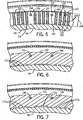
Abstandssteuerung veranschaulicht; 3 an axial partial cross section of the turbine of 1 along an arcuate line 3-3 of 2 and illustrates an embodiment of a turbine housing with coolant channels for pitch control;
4 eine
perspektivische Teilexplosionsansicht des Turbinengehäuses von 3 ist,
die die Baugruppe von Kühlmitteleinsätzen und
einem Verbindungsteil darstellt, die mehrere radiale und axiale Kühlmittelkanäle gemäß einer
Ausführungsform
der vorliegenden Technik definiert; 4 a partial exploded perspective view of the turbine housing of 3 10, which illustrates the assembly of coolant inserts and a connector defining a plurality of radial and axial coolant channels according to one embodiment of the present technique;
5 ein
radialer Teilquerschnitt des Turbinengehäuses von 3 entlang
einer Schnittlinie 5-5 ist und einen Abschnitt eines Kühlmitteleinsatzes mit
mehreren radialen Kühlmittelkanälen gemäß einer
Ausführungsform
der vorliegenden Technik darstellt; 5 a radial partial cross section of the turbine housing of 3 is along a section line 5-5 and illustrates a portion of a coolant insert with a plurality of radial coolant channels according to an embodiment of the present technique;
6 ein
radialer Teilquerschnitt des Turbinengehäuses von 3 entlang
einer Schnittlinie 6-6 ist und einen Abschnitt eines Verbindungsteils
mit mehreren axialen Kühlmittelkanälen gemäß einer Ausführungsform
der vorliegenden Technik darstellt; 6 a radial partial cross section of the turbine housing of 3 is along a section line 6-6 and illustrates a portion of a connecting part with a plurality of axial coolant channels according to an embodiment of the present technique;
7 ein
radialer Teilquerschnitt entlang einer Schnittlinie 6-6 von 3 ist
und einen Abschnitt eines Verbindungsteils mit mehreren axialen
Kühlmittelkanälen gemäß einer
Ausführungsform
der vorliegenden Technik darstellt; 7 a radial partial cross section along a section line 6-6 of 3 and illustrating a portion of a connector having a plurality of axial coolant channels in accordance with an embodiment of the present technique;
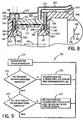
8 ein
detaillierterer axialer Teilquerschnitt des Turbinengehäuses entlang
einer bogenförmigen
Linie 8-8 von 3 und entlang der Schnittstelle
8-8 von 4 ist und einen Kühlmittelstrom durch
die radialen und axialen Kanäle
gemäß einer Ausführungsform
der vorliegenden Technik darstellt; und 8th a more detailed partial axial section of the turbine housing along an arcuate line 8-8 of 3 and along the interface 8-8 of 4 and represents a flow of coolant through the radial and axial channels according to an embodiment of the present technique; and
9 ein
Flussdiagramm ist, das ein Verfahren zum Steuern eines Abstandes
auf der Basis eines Betriebszustandes eines Turbinensystems gemäß einer
Ausführungsform
der vorliegenden Technik darstellt. 9 FIG. 10 is a flowchart illustrating a method for controlling a distance based on an operating condition of a turbine system according to an embodiment of the present technique.
Detaillierte Beschreibung
der ErfindungDetailed description
the invention
Eine
oder mehrere spezifische Ausführungsformen
der vorliegenden Erfindung werden nachstehend beschrieben. In dem
Bemühen,
eine knappe Beschreibung dieser Ausführungsformen zu liefern, können nicht
alle Merkmale einer tatsächlichen
Implementation in der Beschreibung beschrieben werden. Es dürfte erkennbar
sein, dass bei der Entwicklung von jeder derartigen tatsächlichen
Implementation wie bei jedem technischen oder konstruktiven Projekt
zahlreiche implementationsspezifische Entscheidungen getroffen werden
müssen,
um die spezifischen Ziele des Entwicklers, wie z. B. Übereinstimmung
mit systembezogenen und geschäftsbezogenen
Einschränkungen
zu erreichen, welche von einer Implementation zur anderen variieren
können. Ferner
dürfte
erkennbar sein, dass eine derartige Entwicklungsanstrengung komplex
und zeitaufwendig sein kann, aber trotzdem hinsichtlich Auslegung, Herstellung
und Fertigung für
den normalen Fachmann mit dem Vorteil dieser Offenlegung eine Routineaufgabe
wäre.A
or more specific embodiments
The present invention will be described below. By doing
effort
can not provide a concise description of these embodiments
all the characteristics of an actual
Implementation will be described in the description. It should be recognizable
be that in the development of any such actual
Implementation as with any engineering or design project
numerous implementation-specific decisions are made
have to,
to the specific goals of the developer, such. B. match
with systemic and business related
restrictions
which vary from one implementation to another
can. Further
might
It can be seen that such a development effort is complex
and time consuming, but still in terms of design, manufacture
and manufacturing for
the ordinary skilled in the art with the benefit of this disclosure a routine task
would.
Wenn
Elemente verschiedener Ausführungsformen
der vorliegenden Erfindung eingeführt werden, sollen die Artikel ”einer,
eines, eine”, ”der, die,
das” und ”besagter,
besagte, besagtes” die
Bedeutung haben, dass eines oder mehrere von den Elementen vorhanden
sein kann. Die Begriffe ”aufweisend”, ”enthaltend” und ”habend” sollen
einschließend
sein und die Bedeutung haben, dass zusätzliche weitere Elemente außer den
aufgelisteten Elementen vorhanden sein können. Alle Beispiele von Betriebsparametern
und/oder Umgebungsbedingungen schließen weitere Parameter/Bedingungen
der offengelegten Ausführungsformen
nicht aus.If
Elements of various embodiments
of the present invention, the articles "one,
one, one, one, the, the
the "and" said
said, said "the
Meaning that one or more of the elements exist
can be. The terms "having," "containing," and "having" are intended to be
inclusively
be and have the meaning that additional additional elements except the
listed items may be present. All examples of operating parameters
and / or environmental conditions include other parameters / conditions
of the disclosed embodiments
not from.
Wie
nachstehend im Detail beschrieben, betrifft die vorliegende Offenlegung
Abstandssteuerungstechniken unter Verwendung einer Zwangskonvektionskühlung. Derartige
Techniken können
in einem System, wie z. B. in einem Turbinen-basierenden System
(wie z. B. Flugzeug, Lokomotive, Stromerzeugungsgenerator, usw.)
implementiert sein. So wie hierin verwendet, ist der Begriff ”Abstand” oder dergleichen
als ein Zwischenraum oder Spalt zu verstehen, der zwischen einer
oder mehreren Komponenten des Systems vorliegen kann, die sich während des
Betriebs in Bezug zueinander bewegen. Der Abstand kann einem ringförmigen Spalt,
einem geradlinigen Spalt, einem rechteckigen Spalt oder irgendeiner
anderen von dem System abhängigen
Geometrie, Bewegungstyp oder anderen verschiedenen Faktoren entsprechen,
wie der Fachmann erkennt. In einer Anwendung kann der Abstand dem
radialen Spalt oder Zwischenraum zwischen Gehäusekomponenten entsprechen,
die eine oder mehrere rotierende Schaufeln eines Verdichters, einer
Turbine oder dergleichen umgeben. Durch Steuern des Abstandes unter
Anwendung der vorliegend offengelegten Techniken kann die Leckagemenge
zwischen den rotierenden Schaufeln und dem Gehäuse aktiv verringert werden,
um den Betriebswirkungsgrad zu erhöhen, während gleichzeitig die Möglichkeit
des Auftretens eines Reibvorgangs (z. B. eines Kontaktes zwischen Gehäusekomponenten
und den rotierenden Schaufeln) minimiert wird. Wie bekannt, kann
die Leckage jedes beliebige Fluid, wie z. B. Luft, Dampf, Verbrennungsgase
usw. betreffen.As
described in detail below, the present disclosure relates
Distance control techniques using forced convection cooling. such
Techniques can
in a system, such as In a turbine-based system
(such as aircraft, locomotive, power generator, etc.)
be implemented. As used herein, the term "space" or the like
as a gap or gap to be understood between a
or more components of the system that may arise during the
Move operation in relation to each other. The distance may be an annular gap,
a rectilinear gap, a rectangular gap or any
other dependent on the system
Geometry, motion type or other different factors,
as the expert recognizes. In one application, the distance can be
correspond radial gap or gap between housing components,
the one or more rotating blades of a compressor, one
Surrounded turbine or the like. By controlling the distance below
Application of the techniques disclosed herein may reduce the amount of leakage
be actively reduced between the rotating blades and the housing,
to increase the operating efficiency, while at the same time the possibility
the occurrence of a rubbing action (eg, a contact between housing components
and the rotating blades) is minimized. As you know, can
the leakage of any fluid, such. As air, steam, combustion gases
etc. concern.
Gemäß Ausführungsformen
der Erfindung kann ein die hierin offengelegten Abstandssteuerungseinrichtungen
verwendendes Turbinentriebwerk ein Turbinengehäuse mit mehreren radialen und
axialen Kühlmittelkanälen enthalten.
Beispielsweise kann in einer Ausführung einer Turbinenanwendung
mit einer oder mehreren Stufen das Turbinengehäuse für jede Stufe einen ersten und
zweiten Haken enthalten, der dafür
konfiguriert ist, sich jeweils mit einem entsprechenden dritten
und vierten Haken auf einem Deckbandteil zu verbinden, das in Umfangsrichtung
um eine Rotationsachse der Turbine positioniert ist und eine oder
mehrere Turbinenschaufeln umschließt. Eine ringförmige Nut
kann sich radial in jeden von den ersten und zweiten Haken des Turbinengehäuses erstrecken.
Ein Kühlmitteleinsatzelement
mit radialen Nuten auf beiden Seiten kann in jede der ringförmigen Nuten
eingesetzt oder darin versenkt sein. Die radialen Nuten auf jeder
Seite des Kühlmitteleinsatzes
können
fluidführend
verbunden sein, um somit mehrere im Wesentlichen U-förmige Kanäle in jeder
ringförmigen
Nut zu definieren. Ein Verbindungsteil mit mehreren axialen Nuten
kann auf dem Turbinengehäuse
zwischen den ringförmigen Nuten
angeordnet sein, und somit mehrere axiale Kanäle definieren. In einigen Ausführungsformen
kann das Verbindungsteil im Wesentlichen ringförmig sein. Die axialen Kanäle können die
U-förmigen
Kanäle
in dem ersten Haken fluidführend
mit den U-förmigen Kanälen in dem
zweiten Haken verbinden.According to embodiments of the invention, a turbine engine employing the spacing controllers disclosed herein may include a turbine housing having a plurality of radial and axial coolant passages. For example, in one embodiment of a turbine application having one or more stages, the turbine housing for each stage may include first and second hooks configured to each because it is to be connected to a corresponding third and fourth hook on a shroud part which is circumferentially positioned around a rotation axis of the turbine and encloses one or more turbine blades. An annular groove may extend radially into each of the first and second hooks of the turbine housing. A coolant insert with radial grooves on both sides may be inserted into or recessed into each of the annular grooves. The radial grooves on each side of the coolant insert may be fluidically connected to define a plurality of substantially U-shaped channels in each annular groove. A connecting member having a plurality of axial grooves may be disposed on the turbine housing between the annular grooves, and thus define a plurality of axial channels. In some embodiments, the connecting part may be substantially annular. The axial channels may fluidly connect the U-shaped channels in the first hook with the U-shaped channels in the second hook.
Wie
vorstehend diskutiert, kann ein radialer Spalt zwischen den Turbinenschaufeln
und einem Deckband während
des Betriebs aufgrund von Temperaturänderungen oder anderen Faktoren
zunehmen oder abnehmen. Beispielsweise kann, wenn sich die Turbine
während
des Betriebs erwärmt,
eine Wärmeausdehnung
der Turbinengehäusekomponenten
eine radiale Bewegung des Deckbandes von der Rotationsachse weg
bewirken und somit den Abstand zwischen den Schaufeln und dem Deckband vergrößern. Dieses
ist im Allgemeinen unerwünscht, da
Verbrennungsgase, die die Laufschaufeln über den radialen Spalt umgehen,
nicht von den Laufschaufeln erfasst werden und daher nicht in Rotationsenergie
umgewandelt werden. Dieses verringert den Wirkungsgrad und die Leistungsabgabe
des Turbinentriebwerks.As
discussed above, may be a radial gap between the turbine blades
and a shroud while
operation due to temperature changes or other factors
increase or decrease. For example, if the turbine
while
of the factory,
a thermal expansion
the turbine housing components
a radial movement of the shroud away from the axis of rotation
cause and thus increase the distance between the blades and the shroud. This
is generally undesirable because
Combustion gases bypassing the blades via the radial gap
not be captured by the blades and therefore not in rotational energy
being transformed. This reduces the efficiency and the power output
of the turbine engine.
Um
den Abstand zu steuern, kann ein Kühlmittelstrom in die vorstehend
diskutierten U-förmigen und
axialen Kanäle
eingeführt
werden. Das Kühlmittelfluid
kann relativ kühler
als die durch die Turbine strömenden
Verbrennungsgase sein und kann, in einigen Ausführungsformen, Luft sein, die
aus einer oder mehreren Stufen eines Verdichters stammt. In weiteren
Ausführungsformen
kann eine getrennte Luftquelle und/oder Wärmetauscher verwendet werden,
um einen Kühlmittelstrom
zu erzeugen. In weiteren Ausführungsformen
kann auch ein flüssiges Kühlmittel
verwendet werden. Im Betrieb wird das Kühlmittel in einem ersten Satz
von U-förmigen
Kanälen
in den ersten Haken eingeführt.
Das Kühlmittel strömt durch
den ersten Satz der U-förmigen
Kanäle, d.
h., radial zu der und dann von der Rotationsachse weg in von dem
Verbindungsteil definierte entsprechende axiale Kanäle und dann
in einen zweiten Satz von U-förmigen
Kanälen
in dem zweiten Haken. Das Kühlmittel
kann den zweiten Satz U-förmiger
Kanäle in
einen durch eine Außenoberfläche des
Turbinengehäuses
und eine in Umfangsrichtung darum angeordnete Kühlmittelhülse definierten ringförmigen Kanal
verlassen. Das Kühlmittel
kann stromabwärts
(d. h., in Bezug auf dem Strom der Verbrennungsgase) entlang dem
ringförmigen
Kanal strömen
und den ringförmigen
Kanal über
einen oder mehrere Einlässe
auf dem Turbinengehäuse
verlassen, die den ringförmigen
Kanal mit einem Hohlraum auf der Innenoberfläche des Turbinengehäuses verbinden.
So wie hierin verwendet, soll der Begriff ”stromabwärts” als Bezeichnung für die axiale
Strömungsrichtung
des Kühlmittelstroms
durch die Kühlmittelkanäle (z. B.
in derselben Richtung wie die Strömung der Verbrennungsgase durch
die Turbine) verstanden werden, und der Begriff ”stromaufwärts” soll in der Bedeutung der
zu dem Kühlmittelstrom
in der Stromabwärtsrichtung
entgegengesetzten axialen Richtung verstanden werden.Around
To control the distance, a coolant flow in the above
discussed U-shaped and
axial channels
introduced
become. The coolant fluid
can be relatively cooler
as the ones flowing through the turbine
Combustion gases and, in some embodiments, may be air
derived from one or more stages of a compressor. In further
embodiments
a separate air source and / or heat exchanger may be used,
around a coolant flow
to create. In further embodiments
can also be a liquid coolant
be used. In operation, the coolant is in a first set
of U-shaped
channels
inserted in the first hook.
The coolant flows through
the first set of U-shaped
Channels, d.
h., Radially to and then away from the axis of rotation in of the
Connecting part defined corresponding axial channels and then
in a second set of U-shaped
channels
in the second hook. The coolant
may be the second set U-shaped
Channels in
one through an outer surface of the
turbine housing
and a circumferentially disposed therethrough coolant sleeve defined annular channel
leave. The coolant
can be downstream
(i.e., with respect to the flow of combustion gases) along the
annular
Channel flow
and the annular one
Channel over
one or more inlets
on the turbine housing
leave the ring-shaped
Connect the duct to a cavity on the inner surface of the turbine housing.
As used herein, the term "downstream" is intended to refer to the axial
flow direction
of the coolant flow
through the coolant channels (eg
in the same direction as the flow of the combustion gases through
the turbine), and the term "upstream" is intended to be in the meaning of
to the coolant flow
in the downstream direction
be understood opposite axial direction.
Wie
es nachstehend detaillierter diskutiert wird, kann der Kühlmittelstrom
durch die Kühlmittelkanäle (z. B.
die U-förmigen
und axialen Kanäle)
das Turbinengehäuse über eine
Zwangskonvektionskühlung
kühlen,
was der Wärmeausdehnung
des Deckbandes entgegenwirken und/oder diese reduzieren kann. D.
h., das Turbinengehäuse
kann so konfiguriert sein, dass es sich um einen bestimmten Betrag auf
der Basis der Temperatur und/oder Durchflusses des Kühlmittels
in dem Kühlmittelkanal
zusammenzieht oder ausdehnt. Eine Steuerung kann bei dem Turbinensystem
eingesetzt werden, um den Kühlmittelstrom
und/oder die Temperatur aktiv zu steuern. Auf diese Weise kann ein
gewünschter
Abstand in Bezug auf rotierende Schaufeln und das Deckband aktiv
eingehalten werden. In einigen Ausführungsformen können die
Kühlmittelkanäle an verschiedenen Umfangsstellen
des Turbinengehäuses
anders konfiguriert sein. Beispielsweise können Bereiche des Turbinengehäuses, die
für Wärmeeffekte
empfindlicher sind, so konfiguriert sein, dass sie einen größeren Kühlmittelstrom
(z. B. durch eine größere Konzentration
von Kühlmittelkanälen) aufnehmen.
Somit kann ein gewünschter
Abstand selbst dann eingehalten werden, wenn das Turbinengehäuse selbst
unrund ist oder während
des Betriebs (z. B. aufgrund einer durch ungleichmäßige Wärmeausdehnung
bewirkten Deformation) unrund wird. Es sollte angemerkt werden,
dass jeder von den Kühlmitteleinsätzen und
das Verbindungsteil einzeln hergestellt werden können. Somit kann die Herstellung
des Turbinengehäuses
mit den vorstehend erwähnten
Kühlmittelkanälen vereinfacht
werden, indem die Kühlmitteleinsätze und
das Verbindungsteil als getrennte diskrete Komponenten bereitgestellt
werden, die leicht in das Turbinengehäuse in einer modularen Weise
(im Gegensatz zu einer maschinellen Bearbeitung des Turbinengehäuses aus
nur einem einzigen Materialteil) eingebaut werden können.As
As will be discussed in more detail below, the coolant flow
through the coolant channels (eg
the U-shaped
and axial channels)
the turbine housing over a
Forced convection
cool,
what the thermal expansion
counteract the shroud and / or can reduce this. D.
h., the turbine housing
can be configured to be a certain amount up
the basis of the temperature and / or flow of the coolant
in the coolant channel
contracts or expands. A controller may be on the turbine system
be used to control the coolant flow
and / or actively controlling the temperature. This way you can
desired
Distance in relation to rotating blades and the shroud active
be respected. In some embodiments, the
Coolant channels at various circumferential locations
of the turbine housing
be configured differently. For example, areas of the turbine housing, the
for heat effects
are more sensitive, be configured so that they have a larger coolant flow
(eg by a greater concentration
of coolant channels).
Thus, a desired
Distance can be maintained even if the turbine housing itself
is out of round or while
operation (eg due to uneven thermal expansion
caused deformation) becomes out of round. It should be noted
that everyone from the coolant inserts and
the connecting part can be manufactured individually. Thus, the production
of the turbine housing
with the aforementioned
Coolant channels simplified
be by the coolant inserts and
provided the connector as separate discrete components
be easy in the turbine housing in a modular way
(as opposed to machining the turbine housing
only a single piece of material) can be installed.
Ferner
kann zusätzlich
zu Kühlmitteln
ein Heizfluid ebenfalls in die Kühlmittelkanäle eingeführt werden,
um eine Wärmeausdehnung
unter bestimmten Bedingungen zu beschleunigen oder zu erhöhen. Beispielsweise
kann es während Übergangszuständen vorteilhaft
sein, einen größeren radialen
Spalt bereitzustellen, um die Möglichkeit
des Auftretens eines Reibvorgangs wenigstens solange zu vermeiden,
bis der Betrieb einen stabilen Zustand erreicht. Somit dürfte sich,
obwohl die U-förmigen
und axialen Kanäle
hierin als ”Kühlmittelkanäle” bezeichnet
werden, verstehen, dass diesen auch ein Heizfluid zugeführt werden
kann, um den Spalt unter bestimmten Bedingungen zu vergrößern. Demzufolge
kann die Steuerung ferner von Sensoren, wie z. B. Temperatursensoren,
Schwingungssensoren, Positionssensoren usw., gemessene Zustände erfassen.
Abhängig
von den erfassten Bedingungen kann der Spalt verkleinert werden
(indem man z. B. ein Kühlmittel durch
die Kühlmittelkanäle strömen lässt) oder
vergrößert werden
(indem man beispielsweise ein Heizfluid durch die Kühlmittelkanäle strömen lässt), um das
Turbinenbetriebsverhalten wesentlich zu verbessern. Diese Aspekte,
Vorteile und verschiedenen weiteren Merkmale werden nachstehend
unter Bezugnahme auf die 1–9 diskutiert.Further, in addition to coolants, a heating fluid may also be introduced into the coolant channels to accelerate or increase thermal expansion under certain conditions. For example, during transients, it may be advantageous to provide a larger radial gap to avoid the possibility of a friction occurring at least until the operation reaches a steady state. Thus, while the U-shaped and axial channels are referred to herein as "coolant channels," it will be understood that a heating fluid may also be supplied to them to increase the gap under certain conditions. As a result, the controller can also be controlled by sensors such. As temperature sensors, vibration sensors, position sensors, etc., detect measured states. Depending on the conditions sensed, the gap may be reduced (eg, by passing a coolant through the coolant channels) or increased (by, for example, flowing a heating fluid through the coolant channels) to significantly improve turbine performance. These aspects, advantages and various other features will be described below with reference to FIGS 1 - 9 discussed.
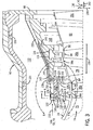
In
Anbetracht des Vorstehenden ist 1 eine Blockdarstellung
eines exemplarischen Systems 10, das ein Gasturbinentriebwerk 12 mit
radialen und axialen Kühlmittelkanälen zur
Abstandssteuerung gemäß Ausführungsformen
der vorliegenden Technik enthält.
In bestimmten Ausführungsformen kann
das System 10 ein Flugzeug, ein Wasserfahrzeug, ein Lokomotivenfahrzeug,
ein Energieerzeugungssystem oder eine Kombination davon beinhalten.
Demzufolge kann das Turbinentriebwerk 12 eine Vielfalt
von Lasten, wie z. B. einen Generator, einen Propeller, ein Getriebe,
ein Antriebssystem oder eine Kombination davon antreiben. Das System 10 kann Flüssig- oder
Gasbrennstoff, wie z. B. Erdgas und/oder wasserstoffreiches synthetisches
Gas, verwenden, um das Turbinensystem 10 zu betreiben. Das
Turbinentriebwerk 12 enthält einen Lufteinlassbereich 14,
einen Verdichter 16, einen Brennerabschnitt 18,
eine Turbine 20 und einen Abgasbereich 22. Gemäß Darstellung
in 1 kann die Turbine 20 zum Antrieb mit
dem Verdichter 16 über
eine Welle 24 verbunden sein.In view of the above 1 a block diagram of an exemplary system 10 , which is a gas turbine engine 12 with radial and axial coolant channels for pitch control according to embodiments of the present technique. In certain embodiments, the system 10 an aircraft, a watercraft, a locomotive vehicle, a power generation system, or a combination thereof. As a result, the turbine engine 12 a variety of loads, such. Example, a generator, a propeller, a transmission, a drive system or a combination thereof. The system 10 can liquid or gas fuel, such as. As natural gas and / or hydrogen-rich synthetic gas, use the turbine system 10 to operate. The turbine engine 12 contains an air inlet area 14 , a compressor 16 , a burner section 18 , a turbine 20 and an exhaust area 22 , As shown in 1 can the turbine 20 to the drive with the compressor 16 over a wave 24 be connected.
Im
Betrieb tritt (durch Pfeile dargestellte) Luft in das Turbinensystem 10 durch
den Lufteinlassbereich 14 ein und kann in dem Verdichter 16 unter Druck
gesetzt werden. Der Verdichter 16 kann mit der Welle 24 verbundene
Verdichterschaufeln 26 enthalten. Die Verdichterschaufeln 26 können den
radialen Spalt zwischen der Welle 24 und einer Innenwand oder
Oberfläche 28 eines
Verdichtergehäuses 30,
in welchem die Verdichterschaufeln 26 angeordnet sind, überspannen.
Beispielsweise kann die Innenwand 28 im Wesentlichen eine
ringförmige
oder konische Form haben. Die Rotation der Welle 24 bewirkt eine
Rotation der Verdichterschaufeln 26, um dadurch Luft in
den Verdichter 16 zu ziehen und die Luft vor dem Eintritt
in den Brennerbereich 18 zu verdichten. Der Verdichterabschnitt 18 enthält ein Brennergehäuse 32,
das konzentrisch oder ringförmig
um die Welle 24 und axial zwischen dem Verdichter 16 und der
Turbine 20 angeordnet ist. In dem Brennergehäuse 32 kann
der Brennerbereich 20 mehrere Brenner 34 enthalten,
die in mehreren Umfangspositionen in einer im Wesentlichen runden
oder ringförmigen Konfiguration
um die Welle 24 herum angeordnet sind. Während die
verdichtete Luft den Verdichter 16 verlässt und in jeden der Brenner 34 eintritt,
kann die verdichtete Luft mit Brennstoff zur Verbrennung in jedem
entsprechenden Brenner 34 vermischt werden. Beispielsweise
kann jeder Brenner 34 eine oder mehrere Brennstoffdüsen enthalten,
die ein Brennstoff/Luft-Gemisch in den Brenner 34 in einem
geeigneten Verhältnis
für optimale
Verbrennung, Emissionen, Brennstoffverbrauch und Energieabgabe einspritzen.
Die Verbrennung der Luft und des Brennstoffs kann heiße unter
Druck stehende Abgase erzeugen, die dann dazu genutzt werden können, eine oder
mehrere Turbinenschaufeln 36 in der Turbine 20 anzutreiben.In operation, air (shown by arrows) enters the turbine system 10 through the air inlet area 14 one and can in the compressor 16 be put under pressure. The compressor 16 can with the wave 24 connected compressor blades 26 contain. The compressor blades 26 can the radial gap between the shaft 24 and an inner wall or surface 28 a compressor housing 30 in which the compressor blades 26 are arranged, span. For example, the inner wall 28 have a substantially annular or conical shape. The rotation of the wave 24 causes a rotation of the compressor blades 26 to thereby air in the compressor 16 to pull and the air before entering the burner area 18 to condense. The compressor section 18 contains a burner housing 32 that is concentric or annular around the shaft 24 and axially between the compressor 16 and the turbine 20 is arranged. In the burner housing 32 can the burner area 20 several burners 34 included in multiple circumferential positions in a substantially circular or circular configuration around the shaft 24 are arranged around. While the compressed air is the compressor 16 leaves and into each of the burners 34 entering, the compressed air can be burned with fuel in each respective burner 34 be mixed. For example, every burner 34 One or more fuel nozzles containing a fuel / air mixture in the burner 34 in an appropriate ratio for optimum combustion, emissions, fuel consumption and energy output. The combustion of the air and fuel may produce hot pressurized exhaust gases which may then be used to form one or more turbine blades 36 in the turbine 20 drive.
Die
Turbine 20 kann die vorstehend erwähnten Turbinenschaufeln 36 und
ein äußeres Turbinengehäuse 40 enthalten.
Wie es nachstehend detaillierter dargestellt wird, kann das äußere Gehäuse 40 ein Deckband 38 enthalten,
das um die Turbinenschaufeln 36 herum angeordnet ist, sowie
ein inneres Turbinengehäuse,
das mit dem Deckband verbunden und konzentrisch in einem äußeren Turbinengehäuse angeordnet
ist. Die Turbinenschaufeln 36 können mit der Welle 24 verbunden
sein und den radialen Spalt zwischen der Welle 24 und dem
Deckband 38, welcher im Wesentlichen ringförmig oder
konisch in der Form sein kann, überspannen.
Ein kleiner radialer Spalt trennt im Wesentlichen die Turbinenschaufeln 36 von
dem Deckband 38, um die Möglichkeit eines Kontaktes zwischen
den Turbinenschaufeln 36 und dem Deckband 38 zu
verringern. Wie es sich versteht, kann der Kontakt zwischen den
Turbinenschaufeln 36 und dem Deckband 38 zu einem
unerwünschten
Zustand führen,
welcher im Allgemeinen als ”Reibvorgang” bezeichnet
wird und einen übermäßigen Verschleiß oder eine
Beschädigung
an einer oder mehreren Komponenten des Turbinentriebwerks 12 bewirken
kann.The turbine 20 may be the turbine blades mentioned above 36 and an outer turbine housing 40 contain. As will be explained in more detail below, the outer housing 40 a shroud 38 included that around the turbine blades 36 is disposed around, and an inner turbine housing, which is connected to the shroud and arranged concentrically in an outer turbine housing. The turbine blades 36 can with the shaft 24 be connected and the radial gap between the shaft 24 and the shroud 38 , which may be substantially annular or conical in shape, straddle. A small radial gap substantially separates the turbine blades 36 from the shroud 38 to the possibility of contact between the turbine blades 36 and the shroud 38 to reduce. As it can be understood, the contact between the turbine blades 36 and the shroud 38 result in an undesirable condition, commonly referred to as "rubbing", and excessive wear or damage to one or more components of the turbine engine 12 can cause.
Die
Turbine 20 kann ein Rotorelement enthalten, das jede von
den Turbinenschaufeln 36 mit der Welle 24 verbindet.
Zusätzlich
enthält
die in der vorliegenden Ausführungsform
dargestellte Turbine 20 drei Stufen, wobei jede einzelne
Stufe durch eine entsprechende von den dargestellten Turbinenschaufeln 36 repräsentiert
wird. Leitvorrichtungen können
zwischen jeder Stufe angeordnet sein, um den Strom der Verbrennungsgase
durch die Turbine 20 zu führen. Es dürfte erkennbar sein, dass weitere Konfigurationen
mehr oder weniger Turbinenstufen enthalten können. Im Betrieb strömen die
in und durch die Turbine 20 strömenden Verbrennungsgase gegen
und zwischen die Turbinenschaufeln 36, um dadurch die Turbinenschaufeln 36 anzutreiben
und somit die Welle 24 zum Antrieb einer Last in Rotation zu
versetzen. Die Rotation der Welle 24 bewirkt auch, dass
die Schaufeln 26 in dem Verdichter 16 die von dem
Einlass 14 erhaltene Luft ansaugen und unter Druck setzen.
Ferner kann in einigen Ausführungsformen
das den Abgasbereich 22 verlassende Abgas als eine Schubquelle
für ein
Fahrzeug, wie z. B. für ein
Strahlflugzeug, verwendet werden.The turbine 20 may include a rotor element, each of the turbine blades 36 with the wave 24 combines. In addition, the turbine shown in the present embodiment includes 20 three stages, each individual stage by a corresponding one of the illustrated turbine blades 36 is represented. louvers can be arranged between each stage to control the flow of combustion gases through the turbine 20 respectively. It will be appreciated that other configurations may include more or fewer turbine stages. In operation, they flow into and through the turbine 20 flowing combustion gases against and between the turbine blades 36 to thereby the turbine blades 36 to drive and thus the wave 24 to drive a load in rotation. The rotation of the wave 24 also causes the blades 26 in the compressor 16 the one from the inlet 14 suck in the air and pressurize it. Further, in some embodiments, this may be the exhaust region 22 leaving exhaust gas as a thrust source for a vehicle, such. B. for a jet aircraft.
Wie
es weiter in 1 dargestellt ist, kann das
Turbinensystem 10 ein Spaltsteuerungssystem 44 enthalten.
Das Spaltsteuerungssystem 44 kann eine Spaltsteuerung 46 sowie
einen oder mehrere Sensoren 48 enthalten, die an verschiedenen
Stellen des Turbinensystems 10 angeordnet sein können. Die
Spaltsteuerung 46 kann verschiedene Hardware- und/oder
Softwarekomponenten enthalten, die zur Ausführung von Routinen und Algorithmen
zum Einstellen des Abstandes (z. B. eines radialen Spaltes) zwischen
den Turbinenschaufeln 36 und dem Deckband 38 verwendet
werden können.
Die Sensoren 48 können
dazu genutzt werden, verschiedene Daten 50 über die
Betriebszustände
des Turbinentriebwerks 12 an die Abstandssteuerung 46 zu übertragen,
sodass die Abstandssteuerung 46 dementsprechend den Abstand
aktiv anpassen kann. Beispielsweise können die Sensoren 48 Temperatursensoren zum
Messen einer Temperatur, Durchflusssensoren zum Messen eines Durchflusses,
Positionssensoren oder irgendwelche andere Sensoren, die für die Detektion
verschiedener Betriebsparameter des Turbinentriebwerks 12,
wie z. B. Drehzahl der Welle 24, Leistungsabgabe, usw.
geeignet sind, enthalten. Obwohl sie mit der Turbine 20 verbunden
dargestellt sind, dürfte
erkennbar sein, dass die Sensoren 48 an/in jeder beliebigen
Komponente des Turbinensystems 10, einschließlich Einlass 14,
Verdichter 16, Brenner 18, Turbine 20 und/oder
Abgasbereich 22, usw. positioniert sein können.How it continues in 1 can be shown, the turbine system 10 a gap control system 44 contain. The gap control system 44 can a gap control 46 and one or more sensors 48 included in different parts of the turbine system 10 can be arranged. The gap control 46 may include various hardware and / or software components necessary to execute routines and algorithms for adjusting the distance (eg, a radial gap) between the turbine blades 36 and the shroud 38 can be used. The sensors 48 can be used to different data 50 about the operating states of the turbine engine 12 to the distance control 46 transfer, so the distance control 46 accordingly can actively adjust the distance. For example, the sensors 48 Temperature sensors for measuring a temperature, flow sensors for measuring a flow, position sensors or any other sensors used for the detection of various operating parameters of the turbine engine 12 , such as B. speed of the shaft 24 , Power output, etc. are included. Although she with the turbine 20 are shown connected, it should be apparent that the sensors 48 on / in any component of the turbine system 10 including inlet 14 , Compressor 16 , Burner 18 , Turbine 20 and / or exhaust area 22 , etc. can be positioned.
Ein
Kühlmittelstrom
kann den Kühlmittelkanälen der
Turbine 20 über
die Zuflussleitungen 52 und 54 zugeführt werden.
Gemäß Darstellung
kann die Zuflussleitung 52 dafür konfiguriert sein, einen aus
dem Verdichter 16 abgezweigten Luftstrom zu liefern. Wie
bekannt, wird in jeder aufeinanderfolgenden Stufe des Verdichters 16 die über den
Einlass 14 aufgenommene Luft einer erhöhten Unter-Druck-Setzung unterzogen
und erhöht
somit ihre Temperatur. Beispielsweise kann die Temperatur der Druckluft
an der achten Stufe eines Verdichters mit sechzehn Stufen zwischen
angenähert
204 bis 316°C
(400 bis 600°F)
haben und die Temperatur der Druckluft in der zwölften Stufe kann angenähert 371
bis 538°C
(700 bis 1000°F)
haben. Während
die Verdichterluft in den Brenner 34 eingespeist wird und
mit Brennstoff reagiert, um den Verbrennungsprozess zu erzielen, kann
die Temperatur der sich ergebenden Verbrennungsgase in dem Brenner 34 Temperaturen
zwischen etwa 1093 bis 1927°C
(2000 bis 3500°F)
oder mehr erreichen. Während
die Verbrennungsgase den Brenner 34 verlassen und in die
Turbine 20 (z. B. als Abgase) eintreten, kann sich die
Temperatur der Verbrennungsgase beispielsweise auf 482 bis 704°C (900 bis
1300°F)
abgekühlt
haben. Somit sollte angemerkt werden, dass die Verdichterluft im
Allgemeinen in Bezug auf die Temperatur der in die Turbine 20 strömenden Verbrennungsgase
immer noch kühler ist.
Demzufolge kann in bestimmten Ausführungsformen die Steuerung 46,
abhängig
von der erforderlichen Kühlmenge,
die zum Aufrechterhalten eines Sollabstandes unter einem speziellen
Satz von Betriebsbedingungen benötigt
wird, dafür
konfiguriert sein, eine Luftquelle für die Zuflussleitung 52 aus
einer der Verdichterstufen auszuwählen oder könnte Luft aus nur einer Verdichterstufe
verwenden und den Durchfluss verändern.A coolant flow may be the coolant channels of the turbine 20 over the inflow pipes 52 and 54 be supplied. As shown, the inflow line 52 be configured to remove one from the compressor 16 to deliver branched airflow. As is known, in each successive stage of the compressor 16 the over the inlet 14 absorbed air subjected to an increased pressurization and thus increases their temperature. For example, the temperature of the compressed air at the eighth stage of a compressor having sixteen stages may be between approximately 204 to 316 ° C (400 to 600 ° F), and the temperature of the compressed air in the twelfth stage may be approximately 371 to 538 ° C (700 to 1000 ° F). While the compressor air in the burner 34 is fed and reacts with fuel to achieve the combustion process, the temperature of the resulting combustion gases in the burner 34 Temperatures between about 1093 to 1927 ° C (2000 to 3500 ° F) or more. While the combustion gases burn the burner 34 leave and into the turbine 20 (eg, as exhaust gases), the temperature of the combustion gases may, for example, have cooled to 482 to 704 ° C (900 to 1300 ° F). Thus, it should be noted that the compressor air is generally in relation to the temperature of the turbine 20 flowing combustion gases is still cooler. As a result, in certain embodiments, the controller may 46 depending on the amount of cooling required to maintain a desired distance under a particular set of operating conditions, be configured to supply an air source to the inflow pipe 52 from one of the compressor stages or could use air from only one compressor stage and change the flow.
Die
Zuflussleitung 54 ist mit einem Wärmetauscher 56 verbunden,
welcher mit einer externen Fluidquelle 58 verbunden ist.
Der Wärmetauscher 56 kann
in das System 10 integriert sein oder kann auf einer getrennten
externen Baugruppe vorgesehen sein. Der Wärmetauscher 56 kann
in Reaktion auf Steuersignale 68 aus der Steuerung 46 die
externe Fluidquelle 58 auf eine Solltemperatur beispielsweise auf
der Basis der gemessenen Daten 50 abkühlen oder erwärmen. Somit
kann abhängig
von der erforderlichen Kühlung
um einen speziellen Sollabstand einzuhalten, die Steuerung 46 entweder
die Zuflussleitung 52 oder 54 zum Liefern eines
Kühlmittelstroms
an die Kühlmittelkanäle in der
Turbine 20 auswählen.
Gemäß Darstellung
kann jede von den Zuflussleitungen 52 und 54 Ventile 60 bzw. 62 enthalten.
Die Steuerung 46 kann die Ventile 60 und 62 über Steuersignale 64 bzw. 66 aktiv
manipulieren, um aktiv einen Durchfluss des Kühlmittels durch die Zuflussleitungen 52 und 54 zu
steuern. Beispielsweise können
die Ventile 60 und 62 dafür konfiguriert sein, einen
Bereich von Durchsätzen
zwischen angenähert
0 bis 6,8 kg/s (0 bis 15 pounds per second) Sekunde zu liefern.
In einer Ausführungsform
können die
Durchsätze
wenigstens angenähert
1,36, 1,82, 2,27, 2,72, 3,18, 3, 63, 4,09 oder 4,54 kg/s (3, 4,
5, 6, 7, 8, 9 oder bis 10 pounds per second) betragen. In einer
weiteren Ausführungsform
können
die Ventile 60 und 62 Ein/Aus-Ventile sein und
die Steuerung kann die Ventile 60 oder 62 zwischen
einem offenen und geschlossenen Zustand umschalten, um einen Kühlmittelstrom
zu erzeugen oder nicht. Zusätzlich kann
wie vorstehend erwähnt,
ein Heizfluid den Kühlmittelkanälen in der
Turbine 20 zugeführt
werden, um den Abstand beispielsweise während Übergangsbetriebsbedingungen
der Turbine zu erhöhen.The inflow line 54 is with a heat exchanger 56 connected, which with an external fluid source 58 connected is. The heat exchanger 56 can in the system 10 be integrated or may be provided on a separate external assembly. The heat exchanger 56 can in response to control signals 68 from the controller 46 the external fluid source 58 to a set temperature, for example based on the measured data 50 cool or heat. Thus, depending on the required cooling to maintain a specific target distance, the controller 46 either the inflow line 52 or 54 for supplying a coolant flow to the coolant channels in the turbine 20 choose. As shown, each of the inflow conduits 52 and 54 valves 60 respectively. 62 contain. The control 46 can the valves 60 and 62 via control signals 64 respectively. 66 actively manipulate to actively flow the coolant through the inflow pipes 52 and 54 to control. For example, the valves 60 and 62 be configured to provide a range of flow rates between approximately 0 to 6.8 kg / s (0 to 15 pounds per second) second. In one embodiment, the flow rates may be at least approximately 1.36, 1.82, 2.27, 2.72, 3.18, 3.63, 4.09, or 4.54 kg / s (3, 4, 5, 6) , 7, 8, 9 or 10 pounds per second). In a further embodiment, the valves 60 and 62 On / off valves can be and the controller can control the valves 60 or 62 switch between an open and closed state to generate a coolant flow or not. In addition, as mentioned above, a heating fluid may be the coolant channels in the turbine 20 be fed to increase the distance, for example, during transient operating conditions of the turbine.
In 2 ist
eine Schnittseitenansicht einer Ausführungsform des schematisch
in 1 gezeigten Turbinentriebwerks 12 dargestellt.
Das Turbinentriebwerk 12 enthält eine oder mehrere innerhalb
eines oder mehrerer Brenner 34 angeordneter Brennstoffdüsen 70.
Im Betrieb tritt Luft in das Turbinentriebwerk 12 durch
den Lufteinlass 14 ein und wird in dem Verdichter 16 unter
Druck gesetzt. Die verdichtete Luft kann dann mit Gas zur Verbrennung
in dem Brenner 34 vermischt werden. Beispielsweise können die
Brennstoffdüsen 70 ein
Brennstoff/Luft-Gemisch in dem Brenner 34 in einem geeigneten
Verhältnis
für optimale
Verbrennung, Emissionen, Brennstoffverbrauch und Leistungsabgabe
einspritzen. Die Verbrennung erzeugt heiße unter Druck stehende Abgase,
welche dann eine oder mehrere Schaufeln 36 in der Turbine 20 antreiben,
um die Welle 24 rotieren zu lassen. Die Rotation der Welle 24 veranlasst
die Verdichterschaufeln 26 in dem Verdichter 16,
durch den Einlass 14 aufgenommene Luft anzusaugen und unter
Druck zu setzen.In 2 is a sectional side view of an embodiment of the schematically in 1 shown turbine engine 12 shown. The turbine engine 12 contains one or more within one or more burners 34 arranged fuel nozzles 70 , During operation, air enters the turbine engine 12 through the air inlet 14 one and gets in the compressor 16 put under pressure. The compressed air can then be burned with gas in the burner 34 be mixed. For example, the fuel nozzles 70 a fuel / air mixture in the burner 34 in an appropriate ratio for optimal combustion, emissions, fuel consumption and power output. The combustion produces hot pressurized exhaust gases, which then form one or more blades 36 in the turbine 20 drive to the shaft 24 to rotate. The rotation of the wave 24 causes the compressor blades 26 in the compressor 16 through the inlet 14 suck in absorbed air and put it under pressure.
Wie
nachstehend detaillierter diskutiert, kann die Turbine 20 ein
mit dem Deckband 38 verbundenes inneres Turbinengehäuse enthalten.
Mehrere radiale und axiale Kühlmittelkanäle können den
von den Zuflussleitungen 52 und/oder 54 bereitgestellten Kühlmittelstrom
wie vorstehend diskutiert aufnehmen. Während der Kühlmittelstrom durch die Kühlmittelkanäle strömt, wird
Wärme aus
dem Turbinengehäuse
aufgrund von Zwangskonvektionskühlungsprinzipien
abgeführt
und somit kann die Wärmeausdehnung
des Turbinengehäuses
und/oder des Deckbandes verringert werden, um somit einen radialen Spalt
zwischen den Turbinenschaufeln 36 und dem Deckband 38 zu
verringern. In einer Ausführungsform
kann das Kühlmittel
ein Teil der über
die Zuflussleitung 52 zugeführten Verdichterluft sein und
kann zwischen 0,1 bis 10 Prozent der gesamten in dem Verdichter 16 strömenden Luft
betragen. Beispielsweise kann der Anteil der über die Zuflussleitung 52 gelieferten
Verdichterluft wenigstens kleiner als etwa 0,1, 0,5, 1, 2, 3, 4,
5, 6, 7, 8, 9 oder 10 Prozent der gesamten Verdichterluft sein.As discussed in more detail below, the turbine may 20 one with the shroud 38 connected inner turbine housing included. Multiple radial and axial coolant passages may be from the inflow conduits 52 and or 54 provided coolant flow as discussed above record. As the coolant stream flows through the coolant channels, heat is removed from the turbine housing due to forced convection cooling principles, and thus the thermal expansion of the turbine housing and / or the shroud can be reduced, thus providing a radial gap between the turbine blades 36 and the shroud 38 to reduce. In one embodiment, the coolant may be part of the via the inflow line 52 supplied compressor air can be between 0.1 to 10 percent of the total in the compressor 16 be flowing air. For example, the proportion of the inflow line 52 supplied compressor air at least less than about 0.1, 0.5, 1, 2, 3, 4, 5, 6, 7, 8, 9 or 10 percent of the total compressor air.
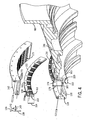
Die
hierin beschriebenen aktiven Abstandssteuerungseinrichtungen werden
besser durch Bezugnahme auf 3 verständlich,
welche einen axialen Teilquerschnitt der Turbine 20 der 1 und 2 entlang
einer bogenförmigen
Linie 3-3 von 2 darstellt. Die dargestellte
Ausführungsform
ist eine dreistufige Turbine gemäß Darstellung
durch die Turbinenschaufeln 36a der ersten Stufe, Turbinenschaufeln 36b der
zweiten Stufe und Turbinenschaufeln 36c der dritten Stufe.
Weitere Ausführungsformen
können
weniger oder mehr Turbinenstufen enthalten. Während die Verbrennungsgase 74 das stromabwärts befindliche
Ende des Brenners 34 verlassen, strömen die Verbrennungsgase 74 durch
die Leiteinrichtung 76 der ersten Stufe, die dafür konfiguriert
ist, die Verbrennungsgase 74 auf die Schaufeln 36a der
ersten Stufe zu lenken. Die Verbrennungsgase 74 strömen dann
durch den Leitapparat 78 der zweiten Stufe zu den Schaufeln 36b der
zweiten Stufe. Schließlich
strömen
die Verbrennungsgase 74 durch den Leitapparat 80 der
dritten Stufe und zu den Schaufeln 36c der dritten Stufe.The active pitch controllers described herein will become better understood by reference to FIG 3 understandably, which is an axial partial cross-section of the turbine 20 of the 1 and 2 along an arcuate line 3-3 of 2 represents. The illustrated embodiment is a three-stage turbine as shown by the turbine blades 36a the first stage, turbine blades 36b the second stage and turbine blades 36c the third stage. Other embodiments may include fewer or more turbine stages. While the combustion gases 74 the downstream end of the burner 34 leave, the combustion gases flow 74 through the guide 76 the first stage configured to burn the combustion gases 74 on the blades 36a to steer the first stage. The combustion gases 74 then flow through the diffuser 78 the second stage to the blades 36b the second stage. Finally, the combustion gases flow 74 through the diffuser 80 the third stage and the blades 36c the third stage.
Gemäß Darstellung
kann die Spitze 86 der Turbinenschaufel 36a von
dem inneren Deckbandbereich 38a durch einen radialen Spalt 84 getrennt
sein. Ebenso kann die Spitze der Turbinenschaufel 36b von
dem inneren Deckbandbereich 38b durch einen radialen Spalt 92 getrennt
sein. Wie vorstehend diskutiert, verringern die radialen Spalte 84 und 92 die Möglichkeit
eines Kontaktes zwischen den Turbinenschaufeln 36a und 36b und
den inneren Deckbandbereichen 38a und 38b und
stellen auch einen Pfad für
Verbrennungsgase 74 zur Umgehung der Turbinenschaufel 36 bereit,
während
die Verbrennungsgase 74 stromabwärts entlang der stromabwärts zeigenden
axialen Richtung 140 gemäß Anzeige durch die Bezugsachsen
strömen.
Wie man erkennen kann, ist ein Gasumgehungspfad im Allgemeinen unerwünscht, da
Energie aus dem Gas des Umgehungspfades durch die Turbinenschaufeln 36 nicht erfasst
und in Rotationsenergie umgewandelt und somit der Wirkungsgrad und
die Leistungsabgabe des Turbinentriebwerks 12 verringert
wird. D. h., der Turbinensystemwirkungsgrad ist wenigstens teilweise
von der Menge der von den Turbinenschaufeln 36 erfassten
Verbrennungsgase abhängig.
Somit kann durch Verkleinerung der radialen Spalte 84 und/oder 92 die
Leistungsabgabe aus der Turbine 20 gesteigert werden. Jedoch
kann, wie vorstehend erwähnt, wenn
der radiale Spalt 84 und/oder 92 zu klein ist,
ein Reibvorgang zwischen den Turbinenschaufeln 36 und dem
Deckband 38 auftreten, was zu einem möglichen Verschleiß und einer
Beschädigung
an Komponenten des Turbinentriebwerks 12 führt.As shown, the top 86 the turbine blade 36a from the inner shroud area 38a through a radial gap 84 be separated. Likewise, the tip of the turbine bucket 36b from the inner shroud area 38b through a radial gap 92 be separated. As discussed above, the radial gaps decrease 84 and 92 the possibility of contact between the turbine blades 36a and 36b and the inner shroud areas 38a and 38b and also provide a path for combustion gases 74 to bypass the turbine blade 36 ready while the combustion gases 74 downstream along the downstream axial direction 140 as indicated by the reference axes. As can be seen, a gas bypass path is generally undesirable because energy from the gas of the bypass path through the turbine blades 36 not captured and converted into rotational energy and thus the efficiency and the power output of the turbine engine 12 is reduced. That is, the turbine system efficiency is at least partially dependent on the amount of turbine blades 36 detected combustion gases dependent. Thus, by reducing the radial gap 84 and or 92 the power output from the turbine 20 be increased. However, as mentioned above, when the radial gap 84 and or 92 too small, a friction between the turbine blades 36 and the shroud 38 resulting in possible wear and damage to components of the turbine engine 12 leads.
Die
offengelegten Ausführungsformen
liefern ein Kühlmittel
an mehrere fluidführend
verbundene radiale und axiale Kühlmittelkanäle in einem
inneren Turbinengehäuse 98,
um einen geeigneten Ausgleich zwischen einer Erhöhung des Wirkungsgrades der
Turbine 20 und einer Verringerung der Kontaktmöglichkeit
oder eines Reibvorgangs zwischen den Turbinenschaufeln 36 und
dem inneren Deckband (z. B. 38a, 38b) zu erzeugen.
Das innere Turbinengehäuse 98 kann
mehrere Haken enthalten, die für
eine Verbindung mit entsprechenden Haken auf den Deckbandsegmenten
konfiguriert sind. Beispielsweise enthält gemäß Bezugnahme auf die erste
Stufe der Turbine 20 das innere Turbinengehäuse 98 Haken 100 und 102,
welche mit entsprechenden Haken 104 bzw. 106 des
inneren Deckbandbereiches 38a in Verbindung stehen. In
der zweiten Stufe enthält
das Turbinengehäuse 98 Haken 110 und 112,
welche mit entsprechenden Haken 114 und 116 des
inneren Deckbandbereiches 38b in Verbindung stehen. Während des
Betriebs des Turbinentriebwerks 12 kann die Wärme aus
den Verbrennungsgasen 74 das innere Turbinengehäuse 98 und
das Deckband 38 zu einer thermischen Ausdehnung, d. h.,
einer Auswärtsbewegung
in der radialen Richtung 136 mit einer größeren Rate
als die Turbinenschaufeln 36 veranlassen. Sobald eine Wärmeausdehnung
auftritt, können die
radialen Spalten 84 und 92 zunehmen. Wie vorstehend
diskutiert, führt
eine Zunahme in dem Abstand dazu, dass mehr Gas die Turbinenschaufeln 36 umgeht,
und somit Turbinenausgangsleistung und Wirkungsgrad verringert.
In einigen Ausführungsformen
können
die inneren Deckbandbereiche 38a und 38b Positionssensoren
enthalten, welche Daten an die Steuerung 46 zur Verwendung
bei der Ermittlung geeigneter Steueraktionen zum Einhalten eines
speziellen Abstandes zurückmelden.The disclosed embodiments provide coolant to a plurality of fluid-conducting connected radial and axial coolant passages in an inner turbine housing 98 to find a suitable balance between increasing the efficiency of the turbine 20 and a reduction in contact possibility or a friction process between the turbine blades 36 and the inner shroud (e.g. 38a . 38b ) to create. The inner turbine housing 98 may include several hooks configured to connect to corresponding hooks on the shroud segments. For example, referring to the first stage of the turbine, for example 20 the inner turbine housing 98 hook 100 and 102 , which with appropriate hooks 104 respectively. 106 of the inner shroud area 38a in Connection stand. In the second stage contains the turbine housing 98 hook 110 and 112 , which with appropriate hooks 114 and 116 of the inner shroud area 38b keep in touch. During operation of the turbine engine 12 can heat out the combustion gases 74 the inner turbine housing 98 and the shroud 38 to a thermal expansion, ie, an outward movement in the radial direction 136 at a greater rate than the turbine blades 36 cause. Once a thermal expansion occurs, the radial gaps 84 and 92 increase. As discussed above, an increase in the distance results in more gas entering the turbine blades 36 bypasses, thus reducing turbine output and efficiency. In some embodiments, the inner shroud areas 38a and 38b Position sensors contain what data to the controller 46 for use in determining appropriate control actions to maintain a specific distance.
Um
den Abstand zu steuern, können
mehrere fluidführend
verbundene radiale und axiale Kühlmittelkanäle in dem
inneren Turbinengehäuse 98 bereitgestellt
sein. Beispielsweise erstrecken sich gemäß Bezugnahme auf die erste
Stufe der Turbine 20 ringförmige Nuten 112 und 120 radial
in die Haken 100 bzw. 102. Kühlmitteleinsätze können in
jede der ringförmigen
Nuten 108 und 120 eingesetzt oder versenkt sein.
Beispielsweise kann ein Kühlmitteleinsatz 122 in
die ringförmige
Nut 118 versenkt sein und ein Kühlmitteleinsatz 124 kann
in die ringförmige
Nut 120 versenkt sein. Obwohl es in der vorliegenden Querschnittsansicht
nicht dargestellt ist, kann jeder von den Kühlmitteleinsätzen 122 und 124 mehrere
radiale Nuten an einer stromaufwärts
liegenden Seite enthalten, wovon jede einer entsprechenden radialen Nut
auf einer stromabwärts
liegenden Seite des Einsatzes entspricht. Wenn sie in ihre entsprechenden Nuten 112 und 120 versenkt
sind, können
die radialen Nuten auf den Kühlmitteleinsätzen 122 und 124 mehrere
U-förmige
Kühlmittelkanäle erzeugen,
wobei jeder radiale Kühlmittelkanal
auf einer stromaufwärts
liegenden Seite eines Kühlmitteleinsatzes
fluidführend
mit einem entsprechenden radialen Kühlmittelkanal auf der stromabwärts liegenden
Seite des Kühlmitteleinsatzes
verbunden ist. Mit anderen Worten, die Kühlmitteleinsätze 122 und 124 können, wenn
sie in ringförmige
Nuten 118 und 120 versenkt sind, mehrere U-förmige Kühlmittelkanäle ausbilden, die
in Umfangsrichtung in jeder ringförmigen Nut 118 und 120 in
Abstand angeordnet sind. Wie es nachstehend diskutiert wird, können die
U-förmigen
Kanäle
in den ringförmigen
Nuten 118 und 120 fluidführend durch mehrere axiale
Kühlmittelkanäle verbunden sein,
um einen Kühlfluidstrom
durch jeden der Haken 100 und 102 (z. B. in den
Richtungen 136 und 138) zu erzeugen.In order to control the distance, a plurality of fluid-conducting connected radial and axial coolant channels in the inner turbine housing 98 be provided. For example, referring to the first stage of the turbine extends 20 annular grooves 112 and 120 radially in the hook 100 respectively. 102 , Coolant inserts can enter each of the annular grooves 108 and 120 be used or sunk. For example, a coolant can be used 122 in the annular groove 118 be sunk and a coolant 124 can in the annular groove 120 be sunk. Although not shown in the present cross-sectional view, any of the coolant inserts may be used 122 and 124 a plurality of radial grooves on an upstream side, each of which corresponds to a corresponding radial groove on a downstream side of the insert. If they are in their corresponding grooves 112 and 120 The radial grooves on the coolant inserts can be recessed 122 and 124 generate a plurality of U-shaped coolant channels, wherein each radial coolant channel is fluidly connected on an upstream side of a coolant insert with a corresponding radial coolant channel on the downstream side of the coolant insert. In other words, the coolant inserts 122 and 124 if they are in annular grooves 118 and 120 are recessed, forming a plurality of U-shaped coolant channels, in the circumferential direction in each annular groove 118 and 120 are spaced apart. As will be discussed below, the U-shaped channels may be in the annular grooves 118 and 120 fluidly passing through a plurality of axial coolant passages to direct cooling fluid flow through each of the hooks 100 and 102 (eg in the directions 136 and 138 ) to create.
Ein
im Wesentlichen ringförmiges äußeres Turbinendeckband 128 kann
konzentrisch mit dem inneren Turbinengehäuse 98 verbunden sein.
Das stromaufwärts
befindliche Ende 132 des äußeren Deckbandes 128 kann
mehrere Einlässe 130 enthalten,
welche in Umfangsrichtung auf dem äußeren Deckband 128 angeordnet
und dafür
konfiguriert sein können,
einen Kühlmittelstrom
aus den Zuflussleitungen 52 und/oder 54 gemäß Darstellung
durch den Pfeil 133 aufzunehmen. Ein Dichtungselement 134 ist
zwischen dem inneren Turbinengehäuse 98 und dem äußeren Deckband 128 angeordnet
und kann dafür
konfiguriert sein, den Kühlmittelstrom 133 in
die radialen Kanäle
auf der stromaufwärts
befindlichen Seite des ersten Kühlmitteleinsatzes 122 zu
lenken. In einer weiteren Ausführungsform
kann das Dichtungselement 134 eine weitere Öffnung(en)
enthalten und kann den Eintritt der radialen Kanäle auf dem Einsatz 122 so überspannen,
dass das Kühlmittel durch
die Öffnung(en)
auf dem Dichtungselement und in die radialen Kanäle des Einsatzes 122 strömt. Demzufolge
kann das Kühlmittel
entlang den radialen Kanälen
auf der stromaufwärts
liegenden Seite des Kühlmitteleinsatzes 122 in
der radialen Richtung 138 (zu der Rotationsachse 139 der
Welle 24 hin) und dann entlang der stromabwärts liegenden
Seite des Kühlmitteleinsatzes 122 in
der entgegengesetzten radialen Richtung 138 (z. B. von
der Rotationsachse 139 der Welle 24 weg) strömen, sodass
der Strömungspfad
im Wesentlichen U-förmig
ist. Das Kühlmittel
kann dann entlang einem oder mehreren im Wesentlichen axialen Kanälen, die
beispielsweise durch Nuten auf einem Verbindungsteil 142 definiert sind,
weiterströmen.
Die axialen Kanäle
verbinden fluidführend
die U-förmigen
Kanäle
in der Nut 118 mit ähnlich
konfigurierten U-förmigen
Kanälen
in der Nut 120. Somit strömt das Kühlmittel in einer axialen Richtung 140 entlang
den axialen Kanälen
des Verbindungsteilers 142 und in radiale Kanäle auf der stromabwärts liegenden
Seite des zweiten Kühlmitteleinsatzes 124 (z.
B. in der Nut 120). Das Kühlmittel strömt dann
in der radialen Richtung 138 entlang einem radialen Kanal
auf der stromabwärts
liegenden Seite des Kühlmitteleinsatzes 124,
und dann in der radialen Richtung 136 entlang entsprechenden
radialen Kanälen
auf der stromabwärts
liegenden Seite des Einsatzes 124.A substantially annular outer turbine shroud 128 can be concentric with the inner turbine casing 98 be connected. The upstream end 132 the outer shroud 128 can have multiple inlets 130 included circumferentially on the outer shroud 128 can be arranged and configured for a flow of coolant from the supply lines 52 and or 54 as shown by the arrow 133 take. A sealing element 134 is between the inner turbine housing 98 and the outer shroud 128 arranged and may be configured for the coolant flow 133 in the radial channels on the upstream side of the first coolant insert 122 to steer. In a further embodiment, the sealing element 134 include another opening (s) and may be the entry of the radial channels on the insert 122 span so that the coolant passes through the opening (s) on the sealing element and into the radial channels of the insert 122 flows. As a result, the coolant may travel along the radial channels on the upstream side of the coolant insert 122 in the radial direction 138 (to the rotation axis 139 the wave 24 down) and then along the downstream side of the coolant insert 122 in the opposite radial direction 138 (eg from the axis of rotation 139 the wave 24 away) so that the flow path is substantially U-shaped. The coolant may then flow along one or more substantially axial channels, for example by grooves on a connecting part 142 are defined, continue to flow. The axial channels fluidly connect the U-shaped channels in the groove 118 with similarly configured U-shaped channels in the groove 120 , Thus, the coolant flows in an axial direction 140 along the axial channels of the connection divider 142 and in radial channels on the downstream side of the second coolant insert 124 (eg in the groove 120 ). The coolant then flows in the radial direction 138 along a radial channel on the downstream side of the coolant insert 124 , and then in the radial direction 136 along respective radial channels on the downstream side of the insert 124 ,
Während der
Kühlmittelstrom
die stromabwärts
liegenden radialen Kanäle
des Einsatzes 124 verlässt,
strömt
das Kühlmittel
in einen zwischen der Außenoberfläche des
inneren Turbinengehäuses 98 und
einer Kühlmitteldichtung 144 definierten
ringförmigen
Kanal 143. Das Kühlmittel
strömt
dann im Wesentlichen entlang der Außenoberfläche des inneren Turbinengehäuses 98 weiter
stromabwärts
(140) und zu mehreren Einlässen 146, welche in
Umfangsrichtung auf dem Turbinengehäuse 98 angeordnet
sein können.
Der Kühlmittelstrom
verlässt
den ringförmigen
Kanal 143 und tritt in den Hohlraum 148 ein. Von hier
aus kann der austretende Kühlmittelstrom
verteilt und/oder weiter stromabwärts zu dem Abgasbereich 22 geführt werden.
Obwohl der Kanal 146 als Ablauf des Kühlmittels in den Hohlraum 148 in
der vorliegenden Ausführungsform
dargestellt ist, könnte der
Kanal 146 in anderen Ausführungsformen an anderen Positionen
entlang des inneren Turbinengehäuses 98,
wie z. B. in der Zone zwischen Haken 110 und 112 angeordnet
sein. Die Konfiguration der hierin diskutierten U-förmigen und
axialen Kanäle
wird nachstehend detaillierter dargestellt und diskutiert.While the coolant flow is the downstream radial channels of the insert 124 leaves, the coolant flows into a between the outer surface of the inner turbine housing 98 and a coolant seal 144 defined annular channel 143 , The coolant then flows substantially along the outer surface of the inner turbine housing 98 further downstream ( 140 ) and to several inlets 146 , which in the circumferential direction on the turbine housing 98 can be arranged. The coolant flow leaves the annular channel 143 and enters the cavity 148 one. From Here, the exiting coolant flow can be distributed and / or further downstream to the exhaust region 22 be guided. Although the channel 146 as drain of the coolant in the cavity 148 In the present embodiment, the channel could be 146 in other embodiments, at other positions along the inner turbine housing 98 , such as In the zone between hooks 110 and 112 be arranged. The configuration of the U-shaped and axial channels discussed herein will be illustrated and discussed in more detail below.
Eine
Zone 150 kann durch das äußere Deckband 128 und
das innere Turbinengehäuse 98 gebildet
werden und kann als eine Begrenzung zwischen dem Kühlmittelstrom
(z. B. durch die U-förmigen
und axialen Kanäle)
und einem Luftstrom durch einen Hohlraum 152 zwischen dem äußeren Turbinengehäuse 40 und
dem äußeren Deckband 128 dienen. Der
Hohlraum kann einen Luftstrom über
die Einlässe 154 und 156 aufnehmen.
Aufgrund von Druckunterschieden, die zwischen der Luft in dem Hohlraum 152 und
dem durch das innere Turbinengehäuse 98 strömenden Kühlmitteln
vorliegen können,
kann die Zone 150 eine Isolation erzeugen. In einigen Ausführungsformen
kann die Zone 150 mit einem isolierenden Material gefüllt sein.A zone 150 can through the outer shroud 128 and the inner turbine housing 98 may be formed as a boundary between the coolant flow (eg through the U-shaped and axial channels) and an air flow through a cavity 152 between the outer turbine housing 40 and the outer shroud 128 serve. The cavity can be a flow of air through the inlets 154 and 156 take up. Due to pressure differences between the air in the cavity 152 and through the inner turbine housing 98 may be present flowing refrigerant, the zone 150 create an isolation. In some embodiments, the zone 150 be filled with an insulating material.
Wie
bekannt, kann, sobald Kühlmittel
durch die U-förmigen
Kanäle
hindurch und in die Haken 100 und 102 strömt, eine
Wärmeübertragung
aufgrund einer Zwangskonvektionskühlung auftreten. Somit kann,
da das innere Turbinengehäuse 98 zunehmend
gekühlt
wird, die Wärmeausdehnung
verringert und somit das innere Turbinengehäuse 98 und insbesondere
die Haken 100 und 102 veranlasst werden, sich
in der radialen Richtung 138 zusammenzuziehen, um den radialen
Spalt 84 zu verkleinern. Beispielsweise kann der Bereich
der Ausdehnung/Zusammenziehung des inneren Turbinengehäuses 98 unter
Anwendung hierin offengelegter Abstandssteuerungstechniken als eine
Funktion des Durchmessers des inneren Gehäuses 98 ausgedrückt werden (z.
B. an dem mit einer Düse
des Brenners 34 gemessenen Ende). Beispielsweise kann der
Ausdehnungs/Zusammenziehungs-Bereich angenähert 10 bis 30 Radial-μm pro cm
Durchmesser (1 bis 3 radial-mil per inch Durchmesser) betragen.
Somit kann beispielsweise unter der Annahme eines Durchmessers von
254 cm (100 inches) eines inneren Gehäuses 98 und eines
Ausdehnungsbetrags von 12,5 Radial-μm pro cm Durchmesser, der Ausdehnungs/Zusammenziehungs-Bereich
des inneren Turbinengehäuses 98 angenähert 1250
Radial-μm
(1,25 Radial-mm) in Bezug auf die Rotationsachse 139 betragen.
Ebenso kann, wenn der Ausdehnungsbetrag 20 Radial-μm pro cm
Durchmesser ist, der Ausdehnungs/Zusammenziehungs-Bereich des inneren
Turbinengehäuses 98 angenähert 2000
Radial-μm
(2 Radial-mm) in Bezug auf die Rotationsachse 139 betragen.
Wiederum dürfte
erkennbar sein, dass die hierin angegebenen spezifischen Beziehungen
nur beispielhaft sind. Tatsächlich
können
abhängig
von der speziellen Implementation, von Betriebstemperaturen, Materialien
und/oder eingesetzten Kühlmitteln, unterschiedliche
Ausdehnungs/Zusammenziehungs-Raten erzielt werden.As is known, once coolant passes through the U-shaped channels and into the hooks 100 and 102 flows, a heat transfer due to forced convection cooling occur. Thus, since the inner turbine housing 98 is increasingly cooled, which reduces thermal expansion and thus the inner turbine housing 98 and especially the hooks 100 and 102 be caused to move in the radial direction 138 contract to the radial gap 84 to downsize. For example, the range of expansion / contraction of the inner turbine housing 98 using pitch control techniques disclosed herein as a function of the diameter of the inner housing 98 be expressed (eg, at the with a nozzle of the burner 34 measured end). For example, the expansion / contraction range may be approximately 10 to 30 radial μm per cm diameter (1 to 3 radial-mil per inch diameter). Thus, for example, assuming a diameter of 254 cm (100 inches) of an inner housing 98 and an expansion amount of 12.5 radial μm per cm diameter, the expansion / contraction area of the inner turbine shell 98 approximately 1250 radial μm (1.25 radial mm) with respect to the axis of rotation 139 be. Likewise, if the expansion amount 20 Radial-μm per cm diameter is the expansion / contraction area of the inner turbine housing 98 Approximately 2000 radial μm (2 radial mm) with respect to the axis of rotation 139 be. Again, it should be understood that the specific relationships set forth herein are exemplary only. In fact, depending on the particular implementation, operating temperatures, materials and / or refrigerants used, different rates of expansion / contraction can be achieved.
Ferner
sollte angemerkt werden, dass eine ähnliche Anordnung von Kühlmittelkanälen in den Haken 110 und 112 implementiert
werden kann, um die Abstandssteuerung des radialen Spaltes 92 zu verbessern.
Tatsächlich
kann abhängig
von der Konfiguration des Turbinentriebwerks 12 die Anordnung der
hierin diskutierten Kühlmittelkanäle in einer
oder mehreren Turbinenstufen implementiert werden. Zur Vereinfachung
sind die Kühlmittelkanäle in 3 nur in
der ersten Stufe der Turbine 20 dargestellt und beschrieben.It should also be noted that a similar arrangement of coolant channels in the hook 110 and 112 can be implemented to the distance control of the radial gap 92 to improve. Actually, depending on the configuration of the turbine engine 12 the arrangement of the coolant channels discussed herein can be implemented in one or more turbine stages. For simplicity, the coolant channels are in 3 only in the first stage of the turbine 20 shown and described.
In 4 ist
eine perspektivische Teilexplosionsansicht des inneren Turbinengehäuses 98,
der Kühlmitteleinsätze 122 und 124 und
des Verbindungsteils 142 gemäß einer Ausführungsform
dargestellt. Der erste Einsatz 122, welcher vollständig aus der
ringförmigen
Nut 128 herausgetreten und mit einer radialen Höhe 184 dargestellt
ist, enthält
radiale Nuten 166 auf einer stromaufwärts liegenden Seite 160 und
radiale Nuten 168 auf einer stromabwärts liegenden Seite 162.
Die radialen Nuten 166 und 168 sind fluidführend durch
einen axialen Zwischenraum 163 an der Basis des Einsatzes 122 verbunden
und definieren somit im Wesentlichen U-förmige Nuten, welche, wenn sie
in die ringförmige
Nut 118 versenkt sind, mehrere erste U-förmige Kanäle definieren. Ferner
können
sich in der vorliegenden Ausführungsform
die radialen Nuten 166 entlang der gesamten radialen Höhe 164 des
Einsatzes 122 erstrecken, während sich die radialen Nuten 168 nur
entlang einem Teil der radialen Höhe 164 erstrecken
können,
sodass das Kühlmittel
in entsprechende axiale Nuten 172 auf der Unterseite 173 des
Verbindungsteils 142 geleitet werden, welches axiale Kanäle ausbildet, wenn
das Verbindungsteil 142 in das innere Turbinengehäuse 98 eingebaut
ist.In 4 is a perspective exploded view of the inner turbine housing 98 , the coolant inserts 122 and 124 and the connecting part 142 represented according to an embodiment. The first use 122 which completely out of the annular groove 128 emerged and with a radial height 184 is shown, contains radial grooves 166 on an upstream side 160 and radial grooves 168 on a downstream side 162 , The radial grooves 166 and 168 are fluid carrying through an axial gap 163 at the base of the insert 122 connected and thus define substantially U-shaped grooves, which, when in the annular groove 118 sunken to define a plurality of first U-shaped channels. Further, in the present embodiment, the radial grooves 166 along the entire radial height 164 of the insert 122 extend while the radial grooves 168 only along a part of the radial height 164 can extend, so that the coolant into corresponding axial grooves 172 on the bottom 173 of the connecting part 142 be guided, which forms axial channels when the connecting part 142 in the inner turbine housing 98 is installed.
Der
zweite Einsatz 124 ist als teilweise aus der ringförmigen Nut 120 herausgetreten
und mit einer radialen Höhe 178 dargestellt.
Abhängig
von der Konfiguration des inneren Turbinengehäuses 98 und der Einsätze 122 und 124 können die
radialen Höhen 164 und 178 dieselben
sein oder sich unterscheiden. Der Einsatz 124 enthält radiale
Nuten 180, die mit der gestrichelten Führungslinie auf einer stromaufwärts liegenden
Seite 174 bezeichnet sind und enthält radiale Nuten 182 auf
einer stromaufwärts
liegenden Seite 176. Die radialen Nuten 180 und 182 sind
fluidführend
durch einen axialen Zwischenraum 183 an der Basis des Einsatzes 124 verbunden
und definieren im Wesentlichen U-förmige Nuten, welche, wenn sie in
die ringförmige
Nut 120 versenkt sind, mehrere zweite U-förmige
Kanäle
definieren. Ferner können sich,
wie dargestellt, die radialen Nuten 180 nur entlang einem
Teil der Höhe 178 erstrecken,
um so den die axialen Kanäle 172 verlassenden
Kühlmittelstrom in
der radialen Richtung 138 zu lenken. Die radialen Nuten 182 können sich
entlang der gesamten radialen Höhe 178 des
Einsatzes 124 erstrecken, um einen Austritt für den Kühlmittelstrom
in den ringförmigen
Kanal 143 (3) bereitzustellen.The second mission 124 is as part of the annular groove 120 emerged and with a radial height 178 shown. Depending on the configuration of the inner turbine housing 98 and the inserts 122 and 124 can the radial heights 164 and 178 be the same or different. The use 124 contains radial grooves 180 with the dashed leader on an upstream side 174 are designated and contains radial grooves 182 on an upstream side 176 , The radial grooves 180 and 182 are fluid carrying through an axial gap 183 at the base of the insert 124 connected and define essentially U-shaped grooves, which, if they in the annular groove 120 sunken to define several second U-shaped channels. Furthermore, as shown, the radial grooves 180 only along a part of the height 178 extend to the axial channels 172 leaving coolant flow in the radial direction 138 to steer. The radial grooves 182 can be along the entire radial height 178 of the insert 124 extend to exit the coolant flow into the annular channel 143 ( 3 ).
Gemäß Ausführungsformen
der vorliegenden Erfindung können
die Kühlmitteleinsätze 122 und 124 im
Wesentlichen den Umfang der ringförmigen Nuten 118 und 120 überspannen,
können
aber aus mehreren Segmenten (z. B. 2 bis 100 Segmenten) ausgebildet
sein. Beispielsweise kann der Kühlmitteleinsatz 122 vier
bogenförmige
Elemente enthalten, wovon jeder 90 Grad des Umfangs der ringförmigen Nut 118 umspannt.
In einer Ausführungsform
kann jedes von den Segmenten unabhängig durch die Steuerung 46 gesteuert
werden. Beispielsweise können
getrennte unabhängige
Kühlmittelströme entlang
den Zuflussleitungen 52 oder 54 bereitgestellt
werden und in die U-förmigen
Kanäle
jedes entsprechenden einzelnen Einsatzsegmentes geleitet werden.
Zusätzlich
kann abhängig
von den thermischen Eigenschaften des inneren Turbinengehäuses 98 dort,
wo sich ein spezielles Einsatzsegment befindet, die Konfiguration
der radialen Nuten auf jedem Einsatzsegment variieren. Beispielsweise
kann ein Einsatz in einem besonders wärmeempfindlichen Bereich des
inneren Turbinengehäuses 98 dafür konfiguriert
sein, mehr Kühlmittel
als andere Segmente aufzunehmen und/oder kann mehr und/oder tiefere radiale
Nuten 166 und 168 enthalten. Zusätzlich können die
Nuten 166 und 168 unterschiedliche Zwischenraumanordnungen
haben. In einer weiteren Ausführungsform
können
die radialen Nuten 166 und 168 im Wesentlichen
für jedes
Segment des Einsatzes 122 gleichförmig sein, und die Steuerung 46 kann
unabhängige
Kühlmittelströme mit variierenden Temperaturen
und/oder Durchsätzen
abhängig
von den Wärmeeigenschaften
jedes Einsatzsegmentes vorgeben. Beispielsweise kann, wenn sich
ein spezieller Bereich des Turbinengehäuses 98 rascher ausdehnt,
die Steuerung 46 einen Kühlmittelstrom aus einer kühleren Verdichterstufe
zuführen
oder alternativ den Durchfluss des Kühlmittels erhöhen. Ebenso kann,
wenn sich ein spezieller Abschnitt des Turbinengehäuses langsamer
ausdehnt, die Steuerung einen Kühlmittelstrom
aus einer wärmeren
oder heißeren
Verdichterstufe zuführen
oder alternativ einen langsameren Durchfluss des Kühlmittels
bereitstellen. In weiteren Ausführungsformen
kann das Turbinengehäuse 98 selbst
und/oder das Kühlteil 142 mehrere
Bereiche enthalten, die durch Schrauben oder irgendeinem anderen
geeigneten Befestigungselementtyp verbunden sind.According to embodiments of the present invention, the coolant inserts 122 and 124 essentially the circumference of the annular grooves 118 and 120 span, but may be formed of multiple segments (eg, 2 to 100 segments). For example, the coolant used 122 four arcuate elements, each 90 degrees of the circumference of the annular groove 118 spans. In one embodiment, each of the segments may be independent of the controller 46 to be controlled. For example, separate independent coolant flows along the supply lines 52 or 54 and directed into the U-shaped channels of each respective single insert segment. Additionally, depending on the thermal characteristics of the inner turbine housing 98 where a special insert segment is located, the configuration of the radial grooves on each insert segment will vary. For example, an insert in a particularly heat-sensitive region of the inner turbine housing 98 be configured to receive more coolant than other segments and / or may have more and / or deeper radial grooves 166 and 168 contain. In addition, the grooves can 166 and 168 have different clearance arrangements. In a further embodiment, the radial grooves 166 and 168 essentially for each segment of the mission 122 be uniform, and the controller 46 may dictate independent coolant flows with varying temperatures and / or flow rates depending on the thermal characteristics of each liner segment. For example, if a specific area of the turbine housing 98 expands faster, the controller 46 supply a coolant flow from a cooler compressor stage or, alternatively, increase the flow rate of the coolant. Likewise, if a particular portion of the turbine housing expands more slowly, the controller may supply coolant flow from a warmer or hotter compressor stage, or alternatively provide slower flow of the coolant. In further embodiments, the turbine housing 98 itself and / or the cooling part 142 contain multiple areas connected by screws or any other suitable fastener type.
Wie
bekannt, kann die unabhängige
Steuerung des Kühlmittelstroms
zu mehreren Bereichen des Einsatzes (welcher segmentiert sein kann),
besonders bei der Behandlung von Unrundheitsproblemen nützlich sein.
Beispielsweise kann das Turbinengehäuse 98 während des
Betriebs aufgrund des Umstandes verformt werden, dass in einigen
Ausführungsformen
das Turbinengehäuse 98 in
einer durch die Wellenmittellinie (z. B. die Rotationsachse 139) verlaufenden
Ebene geteilt sein kann, um einen besseren Zugang zu den internen
Komponenten der Turbine 20 beispielsweise während Wartung
und Instandhaltung zu ermöglichen.
In einer derartigen Konfiguration kann eine horizontale Verbindung
verwendet werden, um die zwei Teile der inneren Turbinengehäusestruktur 98 miteinander
zu verbinden. Beispielsweise kann die Verbindung zwei Gegenflansche
mit Durchgangsschrauben enthalten, die einen Klemmdruck zwischen
den Flanschen erzeugen und somit die Teile des Turbinengehäuses 98 miteinander verbinden.
Jedoch kann die zusätzliche
radiale Dicke aufgrund des Vorhandenseins der Flansche zu einer Wärmereaktion
in der unmittelbaren Nähe
der Flansche führen,
die sich von Rest des Turbinengehäuses 98 entscheidet,
sowie zu einer Diskontinuität
in den Umfangsspannungen, die während
des Betriebs der Turbine 20 entstehen können. Die kombinierte Auswirkung
der thermischen Reaktion und der Spannungsdiskontinuität an den
Flanschverbindungen kann bewirken, dass das Turbinengehäuse 98 während des
Betriebs der Turbine 20 unrund wird. Somit kann durch Zuführen unabhängig steuerbarer
Kühlmittelströme an mehrere
Bereiche des inneren Turbinengehäuses 98 die
Wärmeausdehnung
gesteuert werden, um die Kreisformabweichung des Turbinengehäuses 98 aufgrund
der Unrundheit zu minimieren und somit einen geeigneten Abstand
um den gesamten Umfang der Turbine 20 trotz einer möglichen Kreisformabweichung
des Turbinengehäuses 98 und des
Deckbandes 38 einzuhalten.As is known, independent control of the coolant flow to multiple areas of the insert (which may be segmented) may be particularly useful in the treatment of run out problems. For example, the turbine housing 98 deformed during operation due to the fact that in some embodiments, the turbine housing 98 in a through the shaft centerline (eg the axis of rotation 139 ) extending plane can be divided to better access to the internal components of the turbine 20 For example, during maintenance and service to allow. In such a configuration, a horizontal connection may be used to connect the two parts of the inner turbine housing structure 98 to connect with each other. For example, the connection may include two mating flanges with through bolts which create a clamping pressure between the flanges and thus the parts of the turbine housing 98 connect with each other. However, due to the presence of the flanges, the additional radial thickness can result in a heat reaction in the immediate vicinity of the flanges extending from the rest of the turbine housing 98 decides, as well as to a discontinuity in the hoop stresses that occur during operation of the turbine 20 can arise. The combined effect of thermal reaction and stress discontinuity on the flange connections can cause the turbine housing 98 during operation of the turbine 20 becomes out of round. Thus, by supplying independently controllable coolant flows to multiple areas of the inner turbine housing 98 the thermal expansion can be controlled to the circularity deviation of the turbine housing 98 due to the ovality minimize and thus a suitable distance around the entire circumference of the turbine 20 despite a possible circularity deviation of the turbine housing 98 and the shroud 38 observed.
Vor
der Fortsetzung der Beschreibung sollte angemerkt werden, dass jeder
von den Kühlmitteleinsätzen 122 und 124 und
das Verbindungsteil 142 einzeln (z. B. durch mechanische
Bearbeitung) gefertigt oder hergestellt werden kann. Somit können die
Herstellungskosten des inneren Turbinengehäuses 98 durch die
Bereitstellung von Kühlmitteleinsätzen 122 und 124 und
des Verbindungsteils 142 als diskreten Komponenten verringert
werden, die in das Turbinengehäuse 98 in
einer modularen Weise unter Verwendung beliebiger geeigneter Befestigungstechniken wie
z. B. Bolzen, Schrauben, Schweißnähte usw.
eingebaut werden können.
In weiteren Ausführungsformen
könnte
das Verbindungsteil 142 ein einzelnes festes Teil (z. B.
nicht modular) sein. Zusätzlich
könnte
in einer weiteren Ausführungsform
das Verbindungsteil 142 als ein ringförmiges Element ohne Nuten 172 bereitgestellt
werden, sodass ein ringförmiger
Kanal gebildet wird, wenn das Verbindungsteil 142 an den
Einsätzen 122 und 124 befestigt
wird. In solchen Ausführungsformen
tritt der die Einsätze 122 verlassende
Kühlmittelstrom
in den ringförmigen
Kanal (statt in getrennte entsprechend axiale Nuten) ein und strömt in die
radialen Kanäle
auf den Einsätzen 124.
Lediglich beispielsweise könnte
in derartigen Ausführungsformen
das Verbindungsteil 142 ein ringförmiges Teil aus einem Metallblech
sein, das für
einen Sitz um das innere Turbinengehäuse 98 in einer konzentrischen
Weise angepasst ist, um den ringförmigen Kanal zu definieren,
der die radialen Kanäle auf
den Einsätzen 122 und 124 verbindet.
Ferner dürfte
es sich, obwohl die Nuten 172 in der dargestellten Ausführungsform
als im Wesentlichen in der axialen Richtung 139 gerade
und parallel zueinander verlaufend dargestellt sind, verstehen,
dass die Nuten 172 andere Konfigurationen in unterschiedlichen Ausführungsformen
haben können.
Beispielsweise können
die Nuten 172 auch Kanäle
definieren, die bogenförmig
und/oder v-förmig
(nicht parallel zueinander) sind, oder Kanäle, die eine axiale Komponente
in Verbindung mit radialen und/oder Umfangs-Komponenten (in Bezug
auf die Rotationsachse 139) haben.Before continuing the description, it should be noted that each of the coolant inserts 122 and 124 and the connecting part 142 can be manufactured or manufactured individually (eg by mechanical processing). Thus, the manufacturing cost of the inner turbine housing 98 by providing coolant inserts 122 and 124 and the connecting part 142 be reduced as discrete components in the turbine housing 98 in a modular manner using any suitable attachment techniques, such as e.g. As bolts, screws, welds, etc. can be installed. In further embodiments, the connecting part could 142 a single solid part (eg not modular). In addition, in another embodiment, the connecting part 142 as an annular element without grooves 172 be provided so that an annular channel is formed when the connecting part 142 at the inserts 122 and 124 is attached. In such embodiments, the inserts occur 122 leaving coolant flow in the annular channel (instead of in separate corresponding axial grooves) and flows into the radial channels on the inserts 124 , For example only, in such embodiments could the connecting part 142 a ring-shaped part made of a metal sheet that fits around the inner turbine housing 98 is adapted in a concentric manner to define the annular channel defining the radial channels on the inserts 122 and 124 combines. Further, it is likely, though the grooves 172 in the illustrated embodiment, as substantially in the axial direction 139 are shown running straight and parallel to each other, understand that the grooves 172 other configurations in different embodiments may have. For example, the grooves 172 also define channels that are arcuate and / or v-shaped (not parallel to each other), or channels that have an axial component associated with radial and / or circumferential components (with respect to the axis of rotation 139 ) to have.
Des
Weiteren ist in 5 ein radialer Teilquerschnitt
mit einem Abschnitt des inneren Turbinengehäuses 98 und des Kühlmitteleinsatzes 122 entlang
der Schnittlinie 5-5
von 3 dargestellt. Gemäß Darstellung ist der Kühlmitteleinsatz 122 in
der ringförmigen
Nut 118 versenkt. Die stromaufwärts liegende Seite 160 des
Einsatzes 122 enthält
die vorstehend diskutierten mehreren radialen Nuten 166, welche
radiale Kanäle
ausbilden, wenn sie in der ringförmigen
Nut 108 versenkt sind. Für die Zwecke dieser Beschreibung
sollen mittels der entsprechenden Nuten auf den Einsätzen 122 oder 124 oder
auf dem Verbindungsteil 142 ausgebildete Kühlmittelkanäle mit gleichen
Bezugszeichen bezeichnet sein.Furthermore, in 5 a partial radial cross section with a portion of the inner turbine housing 98 and the coolant use 122 along the section 5-5 of 3 shown. As shown, the coolant is used 122 in the annular groove 118 sunk. The upstream side 160 of the insert 122 includes the multiple radial grooves discussed above 166 which form radial channels when in the annular groove 108 sunk. For the purposes of this description, by means of the corresponding grooves on the inserts 122 or 124 or on the connecting part 142 trained coolant channels be denoted by the same reference numerals.
In
der vorliegenden Ausführungsform
sind die radialen Kanäle 166 in
Vierer-Gruppen angeordnet, obwohl jede beliebige andere geeignete
Anordnung implementiert werden kann. Zwischen jeder Gruppierung
der radialen Kanäle 166 kann
der Einsatz 122 einen nutenfreien Abschnitt 189 mit
einer Öffnung 194 enthalten.
Die Öffnungen 194 können für die Aufnahme
eines Bolzens oder Schraube oder irgendeines anderen geeigneten
Befestigungselementtyps konfiguriert sein, um den Einsatz 122 an dem
inneren Turbinengehäuse 98 während des
Zusammenbaus zu befestigen. Wie vorstehend diskutiert, wird ein
Kühlmittelstrom
in jeden von den radialen Kanälen 166 auf
der stromaufwärts
liegenden Seite 160 des Einsatzes 122 gemäß Darstellung durch
Strömungspfeile 190 geführt. Das
Kühlmittel strömt radial
zu der Rotationsachse 139 (3) der Welle 24 und
durch die axialen Zwischenräume 163 in
entsprechende radiale Kanäle 168 auf
der stromabwärts
liegenden Seite 162 (dargestellt durch gestrichelte Pfeile
und Führungslinien).
Wie vorstehend diskutiert, können
sich die radialen Kanäle 168 nur entlang
einem Teil der radialen Höhe 164 erstrecken, um
somit den Kühlmittelstrom
in entsprechende stromabwärts
befindliche axiale Kanäle 172 zu
lenken, die auf dem Verbindungsteil 142 ausgebildet sind.In the present embodiment, the radial channels are 166 arranged in groups of four, although any other suitable arrangement can be implemented. Between each grouping of radial channels 166 can the use 122 a groove-free section 189 with an opening 194 contain. The openings 194 may be configured to receive a bolt or screw or any other suitable fastener type to the insert 122 on the inner turbine housing 98 during assembly. As discussed above, a flow of coolant into each of the radial channels 166 on the upstream side 160 of the insert 122 as shown by flow arrows 190 guided. The coolant flows radially to the axis of rotation 139 ( 3 ) the wave 24 and through the axial spaces 163 in corresponding radial channels 168 on the downstream side 162 (represented by dashed arrows and guide lines). As discussed above, the radial channels 168 only along a part of the radial height 164 extend, so the coolant flow into corresponding downstream axial channels 172 to direct that on the connecting part 142 are formed.
In 6 ist
ein radialer Teilquerschnitt, der einen Abschnitt des inneren Turbinengehäuses 98 und
des Verbindungsteils 142 entlang der Schnittlinie 6-6 von 3 zeigt,
dargestellt. Wie dargestellt, ist das Verbindungsteil 142 auf
das innere Turbinengehäuse 98 gebaut,
um die axialen Kanäle 172 zu
definieren. Das Verbindungsteil 142 kann Öffnungen 196 enthalten,
welche zu den Öffnungen 194 auf
dem Einsatz 122 ausgerichtet sein können. Somit können sich
Befestigungselemente (z. B. Bolzen oder Schrauben), die zum Befestigen
des Einsatzes 122 an dem inneren Turbinengehäuse 98 verwendet
werden, durch die Öffnungen 196 hindurch
erstrecken, um zusätzlich
das Verbindungsteil 142 an dem Einsatz 122 und
dem inneren Turbinengehäuse 98 zu befestigen.
In der dargestellten Ausführungsform sind
die axialen Kanäle 172 im
Wesentlichen in Vierer-Gruppen angeordnet, sodass sie jeder Gruppe von
in 5 dargestellten radialen U-förmigen Kanälen 1:1 entsprechen. D. h.,
jeder radiale Kanal 168 (auf der stromabwärts befindlichen
Seite 162 des Einsatzes 162) kann fluidführend mit
einem entsprechenden von den dargestellten axialen Kanälen 172 verbunden
sein.In 6 is a partial radial cross section, which is a portion of the inner turbine housing 98 and the connecting part 142 along the section 6-6 of 3 shows shown. As shown, the connecting part 142 on the inner turbine housing 98 built to the axial channels 172 define. The connecting part 142 can have openings 196 included, which to the openings 194 on the insert 122 can be aligned. Thus, fasteners (eg, bolts or screws) may be used to secure the insert 122 on the inner turbine housing 98 be used through the openings 196 extend through, in addition to the connecting part 142 on the insert 122 and the inner turbine housing 98 to fix. In the illustrated embodiment, the axial channels are 172 arranged essentially in groups of four, so that they each group of in 5 represented radial U-shaped channels 1: 1 correspond. That is, each radial channel 168 (on the downstream side 162 of the insert 162 ) can be fluid carrying with a corresponding one of the illustrated axial channels 172 be connected.
In
einigen Ausführungsformen
können
die axialen Kanäle 172 den
radialen Kanälen 168 nicht 1:1
entsprechen. Beispielsweise ist in 7 ein radialer
Teilquerschnitt dargestellt, der eine weitere Ausführungsform
eines Abschnittes des inneren Turbinengehäuses 98 und des Verbindungsteils 142 entlang
der Schnittlinie 6-6 von 3 dargestellt. Hier können die
axialen Kanäle 172 zwei
oder mehr von den radialen Kanälen 169 entsprechen.
Beispielsweise können,
wie dargestellt, die axialen Kanäle 172a fluidführend mit
zwei radialen Kanälen 168 verbunden
sein, und die axialen Kanäle 172b können fluidführend mit
einer gesamten Gruppierung von vier radialen Kanälen 168 verbunden
sein. Wie vorstehend diskutiert, kann das die radialen Kanäle 168 verlassende
Kühlmittel
in der axialen Richtung (Richtung 140 in 3)
stromabwärts
zu mehreren zweiten U-förmigen
Kanälen
auf dem Einsatz 124 in der ringförmigen Nut 120 strömen. Das
Kühlmittel
kann die radialen Kanäle 182 auf
der stromabwärts
liegenden Seite des Einsatzes 124 in einen ringförmigen Kanal 143 verlassen,
der durch eine Kühlmitteldichtung 144 und
das innere Turbinengehäuse 98 gebildet
wird.In some embodiments, the axial channels 172 the radial channels 168 not equal 1: 1. For example, in 7 a radial partial cross-section is shown, which is another embodiment of a portion of the inner turbine housing 98 and the connecting part 142 along the section 6-6 of 3 shown. Here you can see the axial channels 172 two or more of the radial channels 169 correspond. For example, as shown, the axial channels 172a fluid carrying with two radial channels 168 be connected, and the axial channels 172b can carry fluid with a total grouping of four radial channels 168 be connected. As discussed above, this may be the radial channels 168 leaving coolant in the axial direction (direction 140 in 3 ) downstream to a plurality of second U-shaped channels on the insert 124 in the annular groove 120 stream. The coolant can be the radial channels 182 on the downstream side of the insert 124 in an annular channel 143 leave that by a coolant seal 144 and the inner turbine housing 98 is formed.
Der
Durchflusspfad des Kühlmittels
durch die U-förmigen und
axialen Kanäle
wird besser verständlich,
wenn er unter Bezugnahme auf 8 beschrieben
wird, welche ein detaillierterer axialer Teilquerschnitt des inneren
Turbinengehäuses 98 entlang
der bogenförmigen
Linie 8-8 von 3 und entlang der Schnittlinie
8-8 von 5 ist. Gemäß Darstellung in 8 tritt
ein Kühlmittelstrom 133,
welcher durch die Kühlmittelzuflussleitungen 52 oder 54 (mittels
der Steuerung 46) zugeführt
werden kann, in Einlässe 130 ein,
welche in Umfangsrichtung entlang dem stromaufwärts liegenden Ende 132 des äußeren Deckbandes 128 angeordnet
sein können.
Der Kühlmittelstrom 133 tritt
in den Hohlraum 198 ein und wird in den radialen Kanal 166 (Pfeil 190)
in der Richtung 138 geleitet. Wie vorstehend diskutiert,
ist der radiale Kanal 166 durch radiale Nuten auf der stromaufwärts liegenden
Seite des Einsatzes 122 definiert, wenn dieser in die ringförmige Nut 118 eingesetzt
ist. Das Kühlmittel
strömt
weiter in der Richtung 138, bis es den axialen Zwischenraum 163 erreicht.
Hier kehrt der Kühlmittelstrom
um (Pfeil 220) und strömt
in der Richtung 136 entlang dem radialen Kanal 168.
Aus dem radialen Kanal 168 tritt das Kühlmittel in einen axialen Kanal 172 ein,
welcher durch den Aufbau des Verbindungsteils 142 auf das
innere Turbinengehäuse 98 ausgebildet
werden kann.The flow path of the coolant through the U-shaped and axial channels will be better understood when referring to FIG 8th be which is a more detailed partial axial section of the inner turbine housing 98 along the arcuate line 8-8 of 3 and along the section line 8-8 of 5 is. As shown in 8th a coolant flow occurs 133 passing through the coolant supply lines 52 or 54 (by means of the controller 46 ) can be supplied in inlets 130 which extends circumferentially along the upstream end 132 the outer shroud 128 can be arranged. The coolant flow 133 enters the cavity 198 and enters the radial channel 166 (Arrow 190 ) in that direction 138 directed. As discussed above, the radial channel is 166 by radial grooves on the upstream side of the insert 122 defined when this in the annular groove 118 is used. The coolant continues to flow in the direction 138 until there is the axial gap 163 reached. Here, the coolant flow reverses (arrow 220 ) and flows in the direction 136 along the radial channel 168 , From the radial channel 168 the coolant enters an axial channel 172 a, which by the construction of the connecting part 142 on the inner turbine housing 98 can be trained.
Das
Kühlmittel
strömt
weiter entlang dem axialen Kanal 172 (Pfeil 202)
und tritt in einen radialen Kanal 180 auf der stromaufwärts liegenden
Seite des Einsatzes 124 ein. Das Kühlmittel wird durch den radialen
Kanal (Pfeil 204) in der Richtung 138 geleitet,
bis es den axialen Zwischenraum 183 erreicht. Das Kühlmittel
strömt
dann in Richtung 136 durch den radialen Kanal 182 (Pfeil 206)
und verlässt schließlich den
radialen Kanal 182 und tritt in den ringförmigen Kanal 143 ein,
welcher, wie vorstehend diskutiert, durch die Außenoberfläche des inneren Turbinengehäuses 98 und
die Kühlmitteldichtung 144 definiert
ist. Das Kühlmittel
strömt
dann weiter stromabwärts
(Richtung 140) und tritt schließlich in den ringförmigen Kanal 142 über einen
oder mehrere Einlässe 146 (3)
aus. Wie vorstehend diskutiert, kann eine Zone 150 zwischen
dem inneren Turbinengehäuse 98 und
dem äußeren Deckband 128 definiert
sein.The coolant continues to flow along the axial channel 172 (Arrow 202 ) and enters a radial channel 180 on the upstream side of the insert 124 one. The coolant is passed through the radial channel (arrow 204 ) in that direction 138 passed until there is the axial gap 183 reached. The coolant then flows in the direction 136 through the radial channel 182 (Arrow 206 ) and finally leaves the radial channel 182 and enters the annular channel 143 which, as discussed above, passes through the outer surface of the inner turbine housing 98 and the coolant seal 144 is defined. The coolant then flows further downstream (direction 140 ) and finally enters the annular channel 142 via one or more inlets 146 ( 3 ) out. As discussed above, a zone 150 between the inner turbine housing 98 and the outer shroud 128 be defined.
Wie
vorstehend diskutiert, ermöglicht
der Kühlmittelstrom
durch die U-förmigen
Kanäle
eine Wärmeübertragung
durch Zwangskonvektionskühlung.
Durch die Bereitstellung der radialen Kanäle in den Haken 100 und 102 bietet
die vorliegende Technik eine verbesserte Wärmeübertragung in diesen Zonen
und eine effektivere Abstandssteuerung. Insbesondere erzeugen die
Einsätze 122 und 124 mit U-förmigen radialen
Kanälen
eine (z. B. in radialer Richtung 138) tiefere Kühlung in
die Haken 100 und 102 und erzeugen somit eine
größere prozentuale Kühlung in
der radialen Richtung und demzufolge einen größeren Bereich einer Abstandssteuerung.
Im Wesentlichen ermöglicht
das größere Kühlvolumen die
Erzeugung einer größeren Ausdehnung
und Zusammenziehung in dem inneren Turbinengehäuse 98. Wie bekannt,
kann der Grad der erzeugten Ausdehnung und Zusammenziehung in etwa
proportional zu der Tiefe sein, mit welcher sich die U-förmigen radialen
Kanäle
radial in die Haken 100 und 102 erstrecken. Insbesondere
ermöglicht
eine tiefere Kühlung
(z. B. in die Haken 100 und 102 hinein) eine effizientere
Nutzung des Kühlmittels,
um eine verbesserte Zusammenziehung/Ausdehnung des Innengehäuseteils 98 bereitzustellen.
Eine tiefere Kühlung
in den Haken kann eine Wärmebarriere
bereitstellen, welche in eine niedrigere Durchschnittstemperatur des
inneren Turbinengehäuses 98 übergehen
kann. Zusätzlich
können
die mittels des Verbindungsteils 142 gebildeten axialen
Kanäle 172 eine
Wärmebarriere
dergestalt bereitstellen, dass im Wesentlichen eine konstante Temperatur über dem
Zwischenraum zwischen den Einsätzen 122 und 124 und über den axialen
Kanälen 172 (z.
B. in der radialen Richtung 136) vorliegt.As discussed above, the coolant flow through the U-shaped channels allows for heat transfer by forced convection cooling. By providing the radial channels in the hook 100 and 102 For example, the present technique provides improved heat transfer in these zones and more effective pitch control. In particular, the inserts generate 122 and 124 with U-shaped radial channels one (eg in the radial direction 138 ) deeper cooling in the hooks 100 and 102 and thus provide greater percent cooling in the radial direction and, consequently, a greater range of pitch control. In essence, the larger cooling volume allows for greater expansion and contraction in the inner turbine housing 98 , As is known, the degree of expansion and contraction generated may be approximately proportional to the depth at which the U-shaped radial channels radially into the hooks 100 and 102 extend. In particular, allows deeper cooling (eg in the hooks 100 and 102 in) a more efficient use of the coolant to improve contraction / expansion of the inner housing part 98 provide. Lower cooling in the hooks may provide a thermal barrier resulting in a lower average temperature of the inner turbine shell 98 can go over. In addition, the means of the connecting part 142 formed axial channels 172 provide a thermal barrier such that substantially a constant temperature across the gap between the inserts 122 and 124 and over the axial channels 172 (eg in the radial direction 136 ) is present.
Wie
vorstehend diskutiert, können
von den Sensoren 48 erhaltene Daten durch die Abstandssteuerung 46 genutzt
werden, um einen Durchfluss und/oder Temperatur des an einen oder
mehrere Bereiche der Turbine 20 gelieferten Kühlmittels
zu verändern.
Wenn die Steuerung 46 feststellt, dass der Abstand zu verkleinern
ist, kann ein Kühlmittelstrom durch
die radialen Kanäle 166, 168,
den axialen Kanal 172 und die radialen Kanäle 180 und 182 Wärme abführen und
somit die Wärmeausdehnung
des inneren Turbinengehäuses 98 während des
Turbinenbetriebs verringern. Sobald sich das innere Turbinengehäuse 98 zusammenzieht,
können
sich die Haken 100 und 102 radial zu der Rotationsachse 139 der Welle 24 (Richtung 138)
hin zusammenziehen, und somit ebenfalls ein Deckband (z. B. den
inneren Deckbandbereich 38a) veranlassen, sich radial zu der
Rotationsachse 139 (Richtung 138) hin zu bewegen.
Demzufolge wird ein radialer Spalt (z. B. 84) zwischen
dem Deckband 38 und den Turbinenschaufeln 36 verringert,
um dadurch die Turbinenausgangsleistung und den Wirkungsgrad zu
erhöhen.As discussed above, from the sensors 48 data obtained by the distance control 46 be used to measure a flow and / or temperature of one or more areas of the turbine 20 to change the delivered coolant. If the controller 46 determines that the distance is to be reduced, a flow of coolant through the radial channels 166 . 168 , the axial channel 172 and the radial channels 180 and 182 Dissipate heat and thus the thermal expansion of the inner turbine housing 98 during turbine operation. As soon as the inner turbine housing 98 can contract, the hooks can 100 and 102 radially to the axis of rotation 139 the wave 24 (Direction 138 ), and thus also a shroud (eg the inner shroud area 38a ), move radially to the axis of rotation 139 (Direction 138 ) to move. As a result, a radial gap (e.g. 84 ) between the shroud 38 and the turbine blades 36 reduced, thereby increasing the turbine output and the efficiency.
Zusätzlich kann
in einigen Ausführungsformen
auch ein Heizfluid in die radialen Kanäle 166, 168,
den axialen Kanal 172 und die radialen Kanäle 180 und 182 eingeführt werden,
um die Wärmeausdehnung
zu vergrößern oder
zu beschleunigen, wie z. B. während Übergangsbetriebszustände. Beispielsweise
kann es während
eines Hochfahrvorgangs vorteilhaft sein, ein größeres Abstandsmaß bereitzustellen,
um die Möglichkeit
eines Reibvorgangs wenigstens bis zu dem Zeitpunkt zu vermeiden,
bis stabile Betriebszustände
erreicht werden.Additionally, in some embodiments, a heating fluid may also enter the radial channels 166 . 168 , the axial channel 172 and the radial channels 180 and 182 be introduced to increase the thermal expansion or accelerate, such. During transient operating conditions. For example, during a start-up operation, it may be advantageous to provide a greater amount of clearance to avoid the possibility of friction at least until the time when stable operating conditions are achieved.
In 9 ist
ein Computer-implementiertes Verfahren 212 zum aktiven
Anpassen des Abstandes auf der Basis gemessener Parameter des Turbinentriebwerks 12 dargestellt.
Das Verfahren 212 kann mit der Überwachung eines oder mehrerer
Parameter des Turbinentriebwerks 12 gemäß Darstellung bei dem Block 214 beginnen.
Die Parameter können durch
die vorstehend diskutierten Turbinensensoren gemessen und dann mit
jedem geeigneten Parameter des Turbinentriebwerks 12 in
Beziehung gesetzt werden, der dazu verwendet werden kann, einen
geeigneten Abstand zu bestimmen. Beispielsweise können sich
einige Parameter auf die Temperatur in der Turbine 20 oder
von bestimmten Komponenten der Turbine 20 (z. B. der Schaufeln 36,
des inneren Turbinengehäuses 98,
usw.), auf Schwingungspegel in der Turbine 20, die Drehzahl
der Welle 24, die Leistungsabgabe des Turbinentriebwerks 12,
einen Durchfluss von Verbrennungsgasen, Druckdaten oder eine beliebige
Kombination davon beziehen. Zusätzlich
können
sich einige Parameter auf ein Steuereingangssignal des Turbinentriebwerks 12 beziehen.
Beispielsweise können
sich einige Parameter auf einen spezifizierten Leistungspegel oder
Betriebszustand des Turbinentriebwerks 12, eine verstrichene
Zeitdauer seit dem Hochfahren des Turbinentriebwerks 12 oder
einen Hochfahr- und/oder Herunterfahr-Eingabebefehl beziehen.In 9 is a computer-implemented method 212 for actively adjusting the distance based on measured parameters of the turbine engine 12 shown. The procedure 212 can with the monitoring of one or more parameters of the turbine engine 12 as shown at the block 214 kick off. The parameters may be measured by the turbine sensors discussed above and then with any suitable parameter of the turbine engine 12 be correlated, which can be used to determine an appropriate distance. For example, some parameters may affect the temperature in the turbine 20 or of certain components of the turbine 20 (eg the blades 36 , the inner turbine housing 98 , etc.), to vibration levels in the turbine 20 , the speed of the shaft 24 , the power output of the turbine engine 12 , a flow of combustion gases, pressure data, or any combination thereof. In addition, some parameters may affect a control input of the turbine engine 12 Respectively. For example, some parameters may be at a specified power level or operating condition of the turbine engine 12 , an elapsed time since the startup of the turbine engine 12 or receive a startup and / or shutdown input command.
Bei
dem Block 214 überwachte
Parameter des Turbinentriebwerks 12 können dazu genutzt werden, um
eine gewünschte
Abstandseinstellung bei den Entscheidungsblöcken 216 und 218 zu
bestimmen. Beispielsweise kann die Steuerung 46 auf der Basis
der im Block 214 gemessenen Parameter bei dem Block 216 bestimmen,
ob die Parameter auf einen Übergangszustand
des Turbinentriebwerks 12 hinweisen, d. h., einen Zustand,
in welchem ein sich ändernder
Parameter des Turbinentriebwerks 12 eine Tendenz zu einer
raschen Änderung
in dem Abstand haben kann. Beispielsweise können einer oder mehrere Parameter
eine Temperatur des äußeren Gehäuses 40,
inneren Gehäuses 98,
der Schaufeln 36 oder irgendeiner anderen Komponente des
Turbinentriebwerks 12 betreffen. Wenn eine rasche Änderung
der Temperatur festgestellt wird, kann dieses darauf hinweisen,
dass sich das Turbinentriebwerk 12 in einem Übergangszustand
wie z. B. Hochfahren oder Herunterfahren befindet.At the block 214 monitored parameters of the turbine engine 12 can be used to set a desired distance in the decision blocks 216 and 218 to determine. For example, the controller 46 on the basis of in the block 214 measured parameter at the block 216 determine if the parameters are on a transient state of the turbine engine 12 point, ie, a state in which a changing parameter of the turbine engine 12 a tendency to have a rapid change in the distance. For example, one or more parameters may be a temperature of the outer housing 40 , inner housing 98 , the shovels 36 or any other component of the turbine engine 12 affect. If a rapid change in temperature is detected, this may indicate that the turbine engine is 12 in a transient state such as B. booting or shutdown is located.
Wenn
ein Übergangszustand
detektiert wird, geht das Verfahren 212 zum Block 218 über, bei
welchem Steueraktionen implementiert werden, um eine Übergangszustandseinstellung
zu erreichen. Beispielsweise können
in einer Ausführungsform
derartige Steueraktionen eine Vergrößerung oder Beschleunigung
der Wärmeausdehnung
des inneren Turbinengehäuses 98 bewirken,
indem man ein Heizfluid durch die Kühlmittelkanäle in die Turbinenhaken 100 und 102 mit
dem Ziel einer Einstellung des Abstandes auf einen maximalen Wert
so schnell wie möglich,
strömen
lässt,
um die Möglichkeit
eines Kontaktes zwischen den Deckbandabschnitten 38 und
den Turbinenschaufeln 36 während des Übergangszustandes zu vermeiden.
Danach kann das Verfahren 212 zu dem Block 214 zurückkehren
und den/die Betriebsparameter des Turbinentriebwerks 12 weiter überwachen.
In einer Ausführungsform kann
die Feststellung, ob das Turbinentriebwerk 12 in einem Übergangszustand
oder stabilen Betriebszustand arbeitet, auch auf der Basis empirischer
Messungen oder theoretischer Abschätzungen unter Berücksichtigung
des Zeitbedarfs basieren, den das Turbinentriebwerk 12 zum
Erreichen eines stabilen Zustandes nach dem Hochfahren oder nach
einer bestimmten anderen Änderung
in der Leistungseinstellung des Turbinentriebwerks 12 benötigt. Die
empirischen Daten können
dann zum Einprogrammieren spezifizierter Zeitkonstanten in die Abstandssteuerung 46 verwendet
werden, die den Zeitaufwand repräsentieren,
der zum Erreichen stabiler Zustände benötigt wird,
nachdem bestimmte Änderungen
in der Leistungseinstellung des Turbinentriebwerks 12 initiiert
worden sind. Beispielsweise kann, nachdem eine spezielle Änderung
in der Leistungseinstellung des Turbinentriebwerks 12 stattgefunden
hat, die Abstandssteuerung 46 den Zeitbedarf verfolgen,
der seit der Änderung
der Leistungseinstellung verstrichen ist, um festzustellen, ob sich
das Turbinentriebwerk 12 in einem Übergangszustand oder stabilen Zustand
befindet. Wenn die verstrichene Zeit größer als die spezifizierte Zeitkonstante
ist, kann dieses darauf hinweisen, dass das Turbinentriebwerk 12 einen
stabilen Betriebszustand erreicht hat. Wenn jedoch die verstrichene
Zeit kürzer
als die spezifizierte Zeitkonstante ist, kann dieses darauf hinweisen, dass
das Turbinentriebwerk 12 sich noch in einem Übergangsbetriebszustand
befindet.If a transient condition is detected, the procedure goes 212 to the block 218 over which control actions are implemented to achieve a transient state setting. For example, in one embodiment, such control actions may increase or accelerate the thermal expansion of the inner turbine housing 98 cause by placing a heating fluid through the coolant channels in the turbine hook 100 and 102 with the aim of setting the distance to a maximum value as fast as possible, to allow for the possibility of contact between the shroud sections 38 and the turbine blades 36 to avoid during the transitional state. After that, the procedure can 212 to the block 214 return and the / the operating parameters of the turbine engine 12 continue to monitor. In one embodiment, the determination of whether the turbine engine 12 operating in a transient state or stable operating state, based also on empirical measurements or theoretical estimates taking into account the time required by the turbine engine 12 to achieve a steady state after startup or after some other change in the power setting of the turbine engine 12 needed. The empirical data may then be used to program specified time constants into the distance control 46 which represent the amount of time needed to achieve stable conditions after certain changes in the power setting of the turbine engine 12 have been initiated. For example, after a specific change in the power setting of the turbine engine 12 took place, the distance control 46 Track the amount of time that has elapsed since the power setting changed to determine if the turbine engine is running 12 is in a transient state or steady state. If the elapsed time is greater than the specified time constant, this may indicate that the turbine engine 12 has reached a stable operating condition. However, if the elapsed time is shorter than the specified time constant, this may indicate that the turbine engine 12 is still in a transient condition.
Ferner
kann bei dem Entscheidungsblock 216, wenn die überwachten
Parameter nicht auf einen Übergangszustand
hinweisen, dann das Verfahren 120 mit dem Entscheidungsblock 220 für den stabilen
Zustand fortfahren. Wenn beispielsweise festgestellt wird, dass
der gemessene Parameter (z. B. die Temperatur) über eine Zeitdauer relativ
konstant ist, kann dieses darauf hinweisen, dass das Turbinentriebwerk 12 einen
stabilen Betriebszustand erreicht hat. Somit fährt das Verfahren 212 mit
dem Schritt 222 fort, bei welchem eine oder mehrere Steueraktionen
implementiert werden, um eine Einstellung für den stabilen Zustand zu erzielen.
Beispielsweise können
derartige Aktionen durch die Steuerung 46 implementiert
werden, um den Abstand zwischen dem Deckband 38 und den
Turbinenschaufeln 36 zu verringern. Beispielsweise kann
die Steuerung 46 einen Kühlmittelstrom einführen, wie
z. B. (durch Manipulieren der Ventile 60 und 62) über die
Zuflussleitungen 52 oder 54. Wie vorstehend diskutiert,
kann das Kühlmittel
durch die U-förmigen Kanäle (166 und 168, 180 und 182)
und axiale Kanäle 172 strömen und
somit die Haken 100 und 102 mittels einer Zwangskonvektionswärmeübertragung
kühlen
und die Wärmeausdehnung
des Turbinengehäuses 98
verringern
oder umkehren. Sobald sich das innere Turbinengehäuse 98 zusammenzieht,
können
sich die Haken 100 und 102 radial (Richtung 138)
zu der Rotationsachse der Welle 24 hin zusammenziehen, und
somit ebenfalls eine Bewegung der Deckbandes (z. B. des inneren
Deckbandbereiches 38a) radial (Richtung 138) zur
Rotationsachse hin bewirken. Demzufolge wird ein radialer Spalt
(z. B. 84) zwischen dem Deckband 38 und den Turbinenschaufeln 36 verringert,
um dadurch Turbinenabgabeleistung und Wirkungsgrad zu erhöhen. Danach
kehrt das Verfahren 212 von dem Block 222 aus
zu dem Block 214 zurück
und fährt
mit der Überwachung
der Betriebsparameter des Turbinentriebwerks 12 fort. Zusätzlich kann
das Verfahren 212 auch von dem Entscheidungsblock 220 zu
dem Block 214 zurückkehren
und die Überwachung
der Turbinenparameter fortsetzen, wenn weder ein Übergangszustand
noch ein stabiler Betriebszustand bei den Entscheidungsblöcken 216 oder 220 detektiert
werden.Further, at the decision block 216 If the monitored parameters do not indicate a transient condition, then the procedure 120 with the decision block 220 continue for steady state. For example, if it is determined that the measured parameter (eg, the temperature) is relatively constant over a period of time, it may indicate that the turbine engine 12 has reached a stable operating condition. Thus, the process moves 212 with the step 222 in which one or more control actions are implemented to achieve a steady state setting. For example, such actions may be controlled by the controller 46 be implemented to the distance between the shroud 38 and the turbine blades 36 to reduce. For example, the controller 46 introduce a flow of coolant, such as. B. (by manipulating the valves 60 and 62 ) via the inflow pipes 52 or 54 , As discussed above, the coolant may pass through the U-shaped channels (FIG. 166 and 168 . 180 and 182 ) and axial channels 172 stream and thus the hooks 100 and 102 Cool by means of a forced convection heat transfer and the thermal expansion of the turbine housing 98 reduce or reverse. As soon as the inner turbine housing 98 can contract, the hooks can 100 and 102 radial (direction 138 ) to the axis of rotation of the shaft 24 pull together, and thus also a movement of the shroud (eg the inner shroud area 38a ) radially (direction 138 ) effect towards the axis of rotation. As a result, a radial gap (e.g. 84) between the shroud 38 and the turbine blades 36 reduced, thereby increasing turbine output and efficiency. After that, the procedure returns 212 from the block 222 out to the block 214 back and continues with the monitoring of the operating parameters of the turbine engine 12 continued. In addition, the process can 212 also from the decision block 220 to the block 214 and continue monitoring the turbine parameters if neither a transient state nor a steady state of operation at the decision blocks 216 or 220 be detected.
Obwohl
sich die vorstehende Beschreibung auf eine Anordnung von Kühlmittelkanälen in Bezug auf
Haken 100 und 102, welche im Wesentlichen der ersten
Stufe der Turbine 20 entsprechen, fokussiert hat, dürfte es
sich verstehen, dass die vorstehend beschriebenen Techniken auch
in anderen Stufen der Turbine 20 angewendet werden könnten. Beispielsweise
kann eine ähnliche
Anordnung von Kühlmittelkanälen in Haken 110 und 112 der
zweiten Stufe der Turbine 20 (3) vorgesehen
sein. Tatsächlich
können
in einer mehrstufigen Turbine 20 die Kühlmittelkanäle in einer oder mehreren von
den Turbinenstufen vorgesehen sein. Ferner dürfte erkennbar sein, dass,
obwohl die vorliegenden Beispiele im Wesentlichen die Anwendungen
der hierin beschriebenen Abstandssteuerungstechniken unter Bezugnahme auf
eine Turbine eines Turbinensystems beschrieben haben, die vorstehenden
Techniken auch auf einen Verdichter des Turbinensystems sowie irgendeine andere
Art von System angewendet werden kann, das eine feststehende Komponente
und eine rotierende Komponente enthält, und in welchen ein Abstand
zwischen den feststehenden und rotierenden Komponenten einzuhalten
ist.Although the above description refers to an arrangement of coolant channels with respect to hooks 100 and 102 which is essentially the first stage of the turbine 20 It should be understood that the techniques described above also apply to other stages of the turbine 20 could be applied. For example, a similar arrangement of coolant channels in hooks 110 and 112 the second stage of the turbine 20 ( 3 ) be provided. In fact, in a multi-stage turbine 20 the coolant channels may be provided in one or more of the turbine stages. Furthermore, while the present examples have substantially described the applications of the spacing control techniques described herein with respect to a turbine of a turbine system, it should be appreciated that the foregoing techniques can also be applied to a compressor of the turbine system, as well as any other type of system that employs a fixed component and a rotating component, and in which a distance between the fixed and rotating components is to be observed.
Diese
Beschreibung nutzt Beispiele, um die Erfindung einschließlich der
besten Ausführungsart offenzulegen,
und um auch jedem Fachmann auf diesem Gebiet zu ermöglichen,
die Erfindung einschließlich
der Herstellung und Nutzung aller Elemente und Systeme und der Durchführung aller
einbezogenen Verfahren in die Praxis umzusetzen. Der patentierbare
Schutzumfang der Erfindung ist durch die Ansprüche definiert und kann weitere
Beispiele umfassen, die für
den Fachmann auf diesem Gebiet ersichtlich sind. Derartige weitere
Beispiele sollen in dem Schutzumfang der Erfindung enthalten sein,
sofern sie strukturelle Elemente besitzen, die sich nicht von dem
Wortlaut der Ansprüche
unterscheiden, oder wenn sie äquivalente
strukturelle Elemente mit unwesentlichen Änderungen gegenüber dem
Wortlaut der Ansprüche
enthalten.These
Description uses examples to the invention including the
to disclose the best way of
and to enable any expert in the field,
the invention including
the manufacture and use of all elements and systems and the implementation of all
put into practice the procedures involved. The patentable
Scope of the invention is defined by the claims and may be further
Examples include, for
those skilled in the art will appreciate. Such others
Examples are intended to be included within the scope of the invention.
if they have structural elements that are not of the
Wording of the claims
differ, or if they are equivalent
structural elements with insignificant changes over the
Wording of the claims
contain.
Ein
System 10 enthält
ein Turbinengehäuse 98 mit
einem ersten Haken 100, der für eine Vereinigung mit einem
zweiten Haken 104 konfiguriert ist, um ein Turbinendeckband 38 um
mehrere Turbinenschaufeln 36 herum zu unterstützen. Das
Turbinengehäuse 98 enthält einen
Kühlmittelkreislauf,
der dafür
konfiguriert ist, den Abstand zwischen dem Turbinendeckband 38 und
den Turbinenschaufeln 36 auf der Basis eines Kühlmittelstroms
durch den Kühlkreislauf
einzustellen. Der Kühlmittelkreislauf
enthält mehrere
sich in den ersten Haken 100 erstreckende erste radiale
Kühlmittelkanäle 166, 168.A system 10 contains a turbine housing 98 with a first hook 100 who is looking for an association with a second hook 104 is configured to a turbine shroud 38 around several turbine blades 36 to support around. The turbine housing 98 includes a coolant loop configured to adjust the distance between the turbine shroud 38 and the turbine blades 36 set on the basis of a flow of coolant through the cooling circuit. The coolant circuit contains several in the first hook 100 extending first radial coolant channels 166 . 168 ,
BezugszeichenlisteLIST OF REFERENCE NUMBERS
-
1010
-
Turbinensystemturbine system
-
1212
-
TurbinentriebwerkTurbine engine
-
1414
-
Einlassinlet
-
1616
-
Verdichtercompressor
-
1818
-
Brennerbereichburner area
-
2020
-
Turbineturbine
-
2222
-
Abgasexhaust
-
2424
-
Wellewave
-
2626
-
Verdichterschaufelcompressor blade
-
2828
-
Innenwandinner wall
-
3030
-
Verdichtergehäusecompressor housing
-
3232
-
Verdichtergehäusecompressor housing
-
3434
-
Brennerburner
-
3636
-
Turbinenschaufelturbine blade
-
3838
-
Innenwandinner wall
-
4040
-
Turbinengehäuseturbine housing
-
4444
-
Steuersystemcontrol system
-
4646
-
Abstandssteuerungdistance control
-
4848
-
Sensorensensors
-
5050
-
Datendates
-
5252
-
Zuflussleitunginflow line
-
5454
-
Zuflussleitunginflow line
-
5656
-
Wärmetauscherheat exchangers
-
5858
-
Fluidquellefluid source
-
6060
-
VentilValve
-
6262
-
VentilValve
-
6464
-
Steuersignalcontrol signal
-
6666
-
Steuersignalcontrol signal
-
6868
-
Steuersignalcontrol signal
-
7070
-
Brennstoffdüsefuel nozzle
-
7474
-
Verbrennungsgasecombustion gases
-
7676
-
Leiteinrichtung
der ersten Stufeguide
the first stage
-
7878
-
Leiteinrichtung
der zweiten Stufeguide
the second stage
-
8080
-
Leiteinrichtung
der dritten Stufeguide
the third stage
-
8484
-
radialer
Spaltradially
gap
-
8686
-
Spitzetop
-
9292
-
radialer
Spaltradially
gap
-
9494
-
Spitzetop
-
9898
-
inneres
Turbinengehäuseinner
turbine housing
-
100100
-
Hakenhook
-
102102
-
Hakenhook
-
104104
-
Hakenhook
-
106106
-
Hakenhook
-
110110
-
Hakenhook
-
112112
-
Hakenhook
-
114114
-
Hakenhook
-
116116
-
Hakenhook
-
118118
-
ringförmige Nutannular groove
-
120120
-
ringförmige Nutannular groove
-
122122
-
KühlmitteleinsatzCoolant flow
-
124124
-
KühlmitteleinsatzCoolant flow
-
128128
-
TurbinendeckbandTurbine shroud
-
130130
-
Einlassinlet
-
132132
-
stromaufwärts liegendes
Endeupstream
The End
-
133133
-
Kühlmittelstrom
(Pfeil)Coolant flow
(Arrow)
-
134134
-
Dichtungselementsealing element
-
136136
-
radiale
Richtungradial
direction
-
138138
-
radiale
Richtungradial
direction
-
139139
-
Rotationsachseaxis of rotation
-
140140
-
axiale
Richtungaxial
direction
-
141141
-
Umfangsrichtungcircumferentially
-
142142
-
Verbindungsteilconnecting part
-
143143
-
ringförmiger Kanalannular channel
-
144144
-
KühlmitteldichtungCoolant seal
-
146146
-
Kanalchannel
-
148148
-
Hohlraumcavity
-
150150
-
ZoneZone
-
152152
-
Hohlraumcavity
-
154154
-
Einlassinlet
-
156156
-
Einlassinlet
-
160160
-
stromaufwärts liegende
Seiteupstream
page
-
162162
-
stromabwärts liegende
Seitedownstream
page
-
163163
-
axialer
Zwischenraumaxial
gap
-
164164
-
radiale
Höheradial
height
-
166166
-
radiale
Nutenradial
groove
-
168168
-
radiale
Nutenradial
groove
-
172172
-
axiale
Nutenaxial
groove
-
173173
-
Unterseitebottom
-
174174
-
stromaufwärts liegende
Seiteupstream
page
-
176176
-
stromabwärts liegende
Seitedownstream
page
-
178178
-
radiale
Höheradial
height
-
180180
-
radiale
Nutenradial
groove
-
182182
-
radiale
Nutenradial
groove
-
183183
-
axialer
Zwischenraumaxial
gap
-
189189
-
nutenfreier
Abschnittnutenfreier
section
-
190190
-
Strömungspfeileflow arrows
-
194194
-
Öffnungopening
-
196196
-
Öffnungopening
-
198198
-
Hohlraumcavity
-
200200
-
Strömungspfeilflow arrow
-
202202
-
Strömungspfeilflow arrow
-
204204
-
Strömungspfeilflow arrow
-
206206
-
Strömungspfeilflow arrow
-
208208
-
Strömungspfeilflow arrow
-
212212
-
Verfahrenmethod
-
214214
-
Blockblock
-
216216
-
Entscheidungsblockdecision block
-
218218
-
Blockblock
-
220220
-
Entscheidungsblockdecision block
-
222222
-
Blockblock