DE102010029651A1 - Method for operating a microlithographic projection exposure apparatus with correction of aberrations induced by rigorous effects of the mask - Google Patents
Method for operating a microlithographic projection exposure apparatus with correction of aberrations induced by rigorous effects of the mask Download PDFInfo
- Publication number
- DE102010029651A1 DE102010029651A1 DE102010029651A DE102010029651A DE102010029651A1 DE 102010029651 A1 DE102010029651 A1 DE 102010029651A1 DE 102010029651 A DE102010029651 A DE 102010029651A DE 102010029651 A DE102010029651 A DE 102010029651A DE 102010029651 A1 DE102010029651 A1 DE 102010029651A1
- Authority
- DE
- Germany
- Prior art keywords
- manipulator
- different
- mask
- pitches
- objective
- Prior art date
- Legal status (The legal status is an assumption and is not a legal conclusion. Google has not performed a legal analysis and makes no representation as to the accuracy of the status listed.)
- Ceased
Links
Images


Classifications
-
- G—PHYSICS
- G03—PHOTOGRAPHY; CINEMATOGRAPHY; ANALOGOUS TECHNIQUES USING WAVES OTHER THAN OPTICAL WAVES; ELECTROGRAPHY; HOLOGRAPHY
- G03F—PHOTOMECHANICAL PRODUCTION OF TEXTURED OR PATTERNED SURFACES, e.g. FOR PRINTING, FOR PROCESSING OF SEMICONDUCTOR DEVICES; MATERIALS THEREFOR; ORIGINALS THEREFOR; APPARATUS SPECIALLY ADAPTED THEREFOR
- G03F7/00—Photomechanical, e.g. photolithographic, production of textured or patterned surfaces, e.g. printing surfaces; Materials therefor, e.g. comprising photoresists; Apparatus specially adapted therefor
- G03F7/70—Microphotolithographic exposure; Apparatus therefor
- G03F7/70058—Mask illumination systems
-
- G—PHYSICS
- G03—PHOTOGRAPHY; CINEMATOGRAPHY; ANALOGOUS TECHNIQUES USING WAVES OTHER THAN OPTICAL WAVES; ELECTROGRAPHY; HOLOGRAPHY
- G03F—PHOTOMECHANICAL PRODUCTION OF TEXTURED OR PATTERNED SURFACES, e.g. FOR PRINTING, FOR PROCESSING OF SEMICONDUCTOR DEVICES; MATERIALS THEREFOR; ORIGINALS THEREFOR; APPARATUS SPECIALLY ADAPTED THEREFOR
- G03F7/00—Photomechanical, e.g. photolithographic, production of textured or patterned surfaces, e.g. printing surfaces; Materials therefor, e.g. comprising photoresists; Apparatus specially adapted therefor
- G03F7/70—Microphotolithographic exposure; Apparatus therefor
- G03F7/70216—Mask projection systems
- G03F7/70283—Mask effects on the imaging process
-
- G—PHYSICS
- G03—PHOTOGRAPHY; CINEMATOGRAPHY; ANALOGOUS TECHNIQUES USING WAVES OTHER THAN OPTICAL WAVES; ELECTROGRAPHY; HOLOGRAPHY
- G03F—PHOTOMECHANICAL PRODUCTION OF TEXTURED OR PATTERNED SURFACES, e.g. FOR PRINTING, FOR PROCESSING OF SEMICONDUCTOR DEVICES; MATERIALS THEREFOR; ORIGINALS THEREFOR; APPARATUS SPECIALLY ADAPTED THEREFOR
- G03F7/00—Photomechanical, e.g. photolithographic, production of textured or patterned surfaces, e.g. printing surfaces; Materials therefor, e.g. comprising photoresists; Apparatus specially adapted therefor
- G03F7/20—Exposure; Apparatus therefor
-
- G—PHYSICS
- G03—PHOTOGRAPHY; CINEMATOGRAPHY; ANALOGOUS TECHNIQUES USING WAVES OTHER THAN OPTICAL WAVES; ELECTROGRAPHY; HOLOGRAPHY
- G03F—PHOTOMECHANICAL PRODUCTION OF TEXTURED OR PATTERNED SURFACES, e.g. FOR PRINTING, FOR PROCESSING OF SEMICONDUCTOR DEVICES; MATERIALS THEREFOR; ORIGINALS THEREFOR; APPARATUS SPECIALLY ADAPTED THEREFOR
- G03F7/00—Photomechanical, e.g. photolithographic, production of textured or patterned surfaces, e.g. printing surfaces; Materials therefor, e.g. comprising photoresists; Apparatus specially adapted therefor
- G03F7/70—Microphotolithographic exposure; Apparatus therefor
- G03F7/70483—Information management; Active and passive control; Testing; Wafer monitoring, e.g. pattern monitoring
- G03F7/70491—Information management, e.g. software; Active and passive control, e.g. details of controlling exposure processes or exposure tool monitoring processes
- G03F7/705—Modelling or simulating from physical phenomena up to complete wafer processes or whole workflow in wafer productions
-
- G—PHYSICS
- G03—PHOTOGRAPHY; CINEMATOGRAPHY; ANALOGOUS TECHNIQUES USING WAVES OTHER THAN OPTICAL WAVES; ELECTROGRAPHY; HOLOGRAPHY
- G03F—PHOTOMECHANICAL PRODUCTION OF TEXTURED OR PATTERNED SURFACES, e.g. FOR PRINTING, FOR PROCESSING OF SEMICONDUCTOR DEVICES; MATERIALS THEREFOR; ORIGINALS THEREFOR; APPARATUS SPECIALLY ADAPTED THEREFOR
- G03F7/00—Photomechanical, e.g. photolithographic, production of textured or patterned surfaces, e.g. printing surfaces; Materials therefor, e.g. comprising photoresists; Apparatus specially adapted therefor
- G03F7/70—Microphotolithographic exposure; Apparatus therefor
- G03F7/70483—Information management; Active and passive control; Testing; Wafer monitoring, e.g. pattern monitoring
- G03F7/7055—Exposure light control in all parts of the microlithographic apparatus, e.g. pulse length control or light interruption
- G03F7/70566—Polarisation control
-
- G—PHYSICS
- G03—PHOTOGRAPHY; CINEMATOGRAPHY; ANALOGOUS TECHNIQUES USING WAVES OTHER THAN OPTICAL WAVES; ELECTROGRAPHY; HOLOGRAPHY
- G03F—PHOTOMECHANICAL PRODUCTION OF TEXTURED OR PATTERNED SURFACES, e.g. FOR PRINTING, FOR PROCESSING OF SEMICONDUCTOR DEVICES; MATERIALS THEREFOR; ORIGINALS THEREFOR; APPARATUS SPECIALLY ADAPTED THEREFOR
- G03F7/00—Photomechanical, e.g. photolithographic, production of textured or patterned surfaces, e.g. printing surfaces; Materials therefor, e.g. comprising photoresists; Apparatus specially adapted therefor
- G03F7/70—Microphotolithographic exposure; Apparatus therefor
- G03F7/70483—Information management; Active and passive control; Testing; Wafer monitoring, e.g. pattern monitoring
- G03F7/70591—Testing optical components
- G03F7/706—Aberration measurement
Abstract
Die Erfindung betrifft ein Verfahren zur Anpassung einer Projektionsbelichtungsanlage für die Mikrolithographie an eine Maske mit Strukturen unterschiedlicher Pitches und/oder unterschiedlicher Strukturbreiten in unterschiedlichen Strukturrichtungen, wobei die durch die Maske induzierten Wellenfrontaberrationen durch einen Manipulator der Projektionsbelichtungsanlage für die Mikrolithographie verringert werden.The invention relates to a method for adapting a projection exposure system for microlithography to a mask with structures of different pitches and / or different structure widths in different structure directions, the wavefront aberrations induced by the mask being reduced by a manipulator of the projection exposure system for microlithography.
Description
Die Erfindung betrifft ein Verfahren zur Anpassung einer Projektionsbelichtungsanlage für die Mikrolithographie.The invention relates to a method for adapting a projection exposure apparatus for microlithography.
Weiterhin betrifft die Erfindung ein Verfahren zum Betrieb einer Projektionsbelichtungsanlage für die Mikrolithographie.Furthermore, the invention relates to a method for operating a projection exposure apparatus for microlithography.
Schließlich betrifft die Erfindung eine Projektionsbelichtungsanlage für die Mikrolithographie, welche zur Durchführung der beiden obigen Verfahren ausgestattet ist.Finally, the invention relates to a projection exposure apparatus for microlithography, which is equipped to carry out the above two methods.
Projektionsbelichtungsanlagen für die Mikrolithographie, im Weiteren kurz Projektionsbelichtungsanlagen genannt, bestehen in der Regel aus einer Lichtquelle, einem, die von der Lichtquelle emittierten Lichtstrahlen zu Beleuchtungslicht verarbeitendem Beleuchtungssystem, einem zu projizierenden Objekt, im Allgemeinen Retikel oder Maske genannt, einem Projektionsobjektiv, im Weiteren kurz Objektiv genannt, welches ein Objektfeld auf ein Bildfeld abbildet, und einem weiteren Objekt, auf welches projiziert wird, im Allgemeinen Wafer genannt. Die Maske oder zumindest ein Teil der Maske befindet sich in dem Objektfeld und der Wafer oder zumindest ein Teil des Wafers befindet sich in dem Bildfeld.Projection exposure systems for microlithography, hereinafter referred to as projection exposure systems, usually consist of a light source, a, the light beams emitted from the light source to illumination light processing illumination system, an object to be projected, generally called reticle or mask, a projection lens, hereinafter briefly Called an objective, which images an object field on one image field, and another object on which is projected, generally called wafer. The mask or at least a part of the mask is located in the object field and the wafer or at least a part of the wafer is located in the image field.
Befindet sich die Maske vollständig in dem Bereich des Objektfeldes, und der Wafer wird ohne eine Relativbewegung von Wafer und Bildfeld belichtet, so wird die Projektionsbelichtungsanlage im Allgemeinen als Wafer-Stepper bezeichnet. Befindet sich nur ein Teil der Maske im Bereich des Objektfeldes, und der Wafer wird während einer relativen Bewegung von Wafer und Bildfeld belichtet, so wird die Projektionsbelichtungsanlage im Allgemeinen als Wafer-Scanner bezeichnet. Die durch die Relativbewegung von Retikel und Wafer definierte räumliche Dimension wird im allgemeinen als Scanrichtung bezeichnet.If the mask is located completely in the region of the object field, and the wafer is exposed without a relative movement of the wafer and the image field, the projection exposure apparatus is generally referred to as a wafer stepper. If only a part of the mask is located in the region of the object field and the wafer is exposed during a relative movement of the wafer and the image field, the projection exposure apparatus is generally referred to as a wafer scanner. The spatial dimension defined by the relative movement of reticle and wafer is generally referred to as scan direction.
Während der Belichtung des Wafers wird die Maske durch das Beleuchtungssystem mit Beleuchtungslicht beleuchtet. Als Setting wird die Art der Beleuchtung bezeichnet. Man unterscheidet zwischen kohärenten Beleuchtung, inkohärenter Beleuchtung mit einem σ-Setting zwischen 0 und 1, annularen Beleuchtungen, X- oder Y-Dipol-Settings mit verschiedenen, ausgeleuchteten Öffnungswinkeln, und Quadrupolsettings. Die gegenwärtige Entwicklung geht in Richtung von Freiformbeleuchtungen, man vl. z. B. „
Für die Integrationsdichte des mit Hilfe des mikrolithograhischen Belichtungsprozesses herzustellenden integrierten Schaltkreises sind periodische Strukturen von entscheidender Bedeutung. Diese werden durch Pitch und Strukturbreite beschrieben. Die auf dem Wafer verwendetet Strukurbreite kann bis zu einem gewissen Grad durch die Lackschwelle des zu belichtenden Resist frei eingestellt werde. Der kleinste erreichbare Pitch, Pitchmin ist hingegen durch die Wellenlänge des Beleuchtungslichtes und die objektseitige numerische Apertur des Objektivs gegeben. Es gilt:
Die Strukturen auf der abzubildenden Maske haben in der Regel zwei Vorzugsrichtungen. Bei der Beurteilung der Abbildungsqualitäten einer Projektionsbelichtungsanlage unterscheidet man daher zumindest zwischen dem maximal auflösbaren Pitch von H-(Horizontal) und V-(Vertikal)-Strukturen. Hierbei sei im Folgenden vereinbart, dass unter einer H-Struktur eine Abfolge von lichtdurchlässigen und lichtundurchlässigen Bereichen der Maske gemeint ist, wobei jeder einzelne dieser Bereiche seine größere Erstreckung orthogonal zur Scanrichtung hat.The structures on the mask to be imaged usually have two preferred directions. When assessing the imaging qualities of a projection exposure apparatus, therefore, a distinction is made at least between the maximum resolvable pitch of H (horizontal) and V (vertical) structures. Hereinafter, it is to be understood that an H-structure means a sequence of light-transmissive and opaque regions of the mask, each individual region having its greater extent orthogonal to the scanning direction.
Die letztendlich auf dem Wafer erreichbare Integrationsdichte einer Projektionsbelichtungsanlage hängt im Wesentlichen von folgenden Parametern ab: (a) Tiefenschärfe DOF des Objektivs, (b) bildseitige numerische Apertur NA und (c) Wellenlänge λ des Beleuchtungslichts. Für den sicheren Betrieb einer Projektionsbelichtungsanlage ist es erforderlich für eine erwünschte Critical Dimension CD, d. h. die kleinste auf dem Wafer vorkommende Strukturbreite, und eine gegebene numerische Apertur NA ein möglichst großes, sogenanntes Prozessfenster aus möglicher Defokussierung FV (Focus variation) und Variation der Dosis des Beleuchtungslichts zu garantieren. Dabei sind NA und DOF antiproportional. Um die Critical Dimension CD weiter zu verringern geht die Entwicklung generell zu steigenden numerischen Aperturen NA. Dies führt aber zu einer Reduzierung der Tiefenschärfe DOF und damit einer Verkleinerung des Prozessfensters.The integration density of a projection exposure apparatus ultimately achievable on the wafer depends essentially on the following parameters: (a) depth of field DOF of the objective, (b) image-side numerical aperture NA and (c) wavelength λ of the illumination light. For the safe operation of a projection exposure apparatus, it is necessary for a desired Critical Dimension CD, i. H. the smallest structure width occurring on the wafer, and a given numerical aperture NA to guarantee the largest possible, so-called process window of possible defocusing FV (Focus variation) and variation of the dose of the illumination light. NA and DOF are antiproportional. To further reduce the Critical Dimension CD, development is generally toward increasing numerical apertures NA. However, this leads to a reduction of the depth of field DOF and thus a reduction of the process window.
Es besteht daher der Bedarf an Massnahmen zur Vergrößerung oder zumindest Stabilisierung des Prozessfensters bei einer sich verringernden Critical Dimension CD.There is therefore a need for measures to increase or at least stabilize the process window with a decreasing critical dimension CD.
Die gegenwärtig besten Auflösungen von Pitch und CD werden durch zwei Klassen von Projektionsbelichtungsanlagen erreicht.The currently best resolutions of pitch and CD are achieved by two classes of projection exposure equipment.
Die erste Klasse von Projektionsbelichtungsanlagen wird mit einen ArF-Laser bei einer Wellenlänge λ des Beleuchtungslichtes von 193 nm mit polarisiertem Licht betrieben und arbeitet im Immersionsbetrieb, d. h. mit einer Flüssigkeit als letztem Medium vor dem Wafer, oder im Trockenbetrieb, d. h. mit einem Gas als letztem Medium vor dem Wafer. Die zugehörigen Objektive, welche die beleuchtete Maske auf den Wafer abbilden, sind in der Regel dioptrische oder katadioptrische Objektive. Diese werden bei bildseitigen numerischen Aperturen von 0.8 bis 1.3 oder auch darüber betrieben. Man vgl. beispielsweise
Die zweite Klasse von Projektionsbelichtungsanlagen wird mit einer Quelle von schwacher Röntgenstrahlung (im Fachjargon als EUV, extreme ultra violett) bei einer Wellenlänge λ des Beleuchtungslichtes von 13.5 nm betrieben. Im Fachjargon spricht man von sogenannten EUV-Systemen oder EUV-Projektionbelichtungsanlagen. Die zugehörigen Objektive, welche die beleuchtete Maske auf den Wafer abbilden, sind katoptrische Objektive. Diese werden bei bildseitigen numerischen Aperturen von 0.2 bis 0.35, 0.9 oder auch darüber betrieben. Man vgl. beispielsweise
In der ersten Klasse von Projektionsbelichtungsanlagen treten die in „
Es besteht daher in dieser ersten Klasse von Projektionsbelichtungsanlagen Bedarf an Maßnahmen zur Korrektur der von den rigorosen Effekten der Maske induzierten (synonym: verursachten) Struktur- und Pitch-abhängigen Aberrationen der Wellenfront und insbesondere besteht Bedarf zur Korrektur des durch die Maske induzierten Struktur- und Pitch-abhängigem Astigmatismus.Therefore, in this first class of projection exposure apparatus, there is a need for measures for correcting the structure-related and pitch-dependent aberrations of the wavefront induced by the rigorous effects of the mask, and in particular, there is a need to correct the pattern-induced and mask-induced aberrations Pitch-dependent astigmatism.
Hierbei wird im Folgenden unter dem von der Struktur oder der Strukturbreite oder dem Pitch induzierten Wellenfrontfehler oder der induzierten Aberration der Wellenfront der Fehler bzw. die Aberration verstanden, deren Ursache ausschließlich durch diese Strukturierung der Maske bedingt ist. Anders formuliert ist dies der Fehler bzw. die Aberration, welche sich zusätzlich zu den anderen, bereits vorhandenen Aberrationen des Objektivs ergibt. Statt von einer induzierten Wellenfrontaberration eines Pitches oder einer Strukturbreite soll auch nur von der Wellenfrontaberration des Pitches oder der Strukturbreite gesprochen werden.Hereinafter, the wavefront error induced by the structure or the structure width or the pitch or the induced aberration of the wavefront is understood to mean the error or the aberration, the cause of which is exclusively due to this structuring of the mask. In other words, this is the error or aberration that results in addition to the other, already existing aberrations of the lens. Instead of an induced wavefront aberration of a pitch or a structure width, it should also be discussed only the wavefront aberration of the pitch or the structure width.
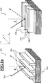
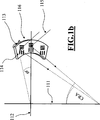
In der zweiten Klasse von Projektionsbelichtungsanlagen findet die Beleuchtung der Maske in Reflektion statt. Daher ist keine telezentrische Beleuchtung der Maske möglich, da sich ansonsten das Beleuchtungssystem und das Objektiv im Wege stehen würden. Der Hauptstrahlwinkel (synonym: Chief Ray Angle) CRA, ist im Falle einer Projektionsbelichtungsanlagen der ersten Klasse die Abweichung des Hauptstrahls von einem telezentrischen Strahl. Im vorliegenden Fall einer Projektionsbelichtungsanlage der zweiten Klasse ist es der Winkel des Hauptstrahles des Beleuchtungslichtes zu einer bzgl. der Objektebene des Objektivs gedachten Orthogonalen. Bei einer Projektionsbelichtungsanlage, wie sie in
Für die nachfolgend beschriebenen Effekte vgl. man auch mit „
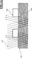
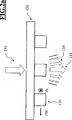
Wie nachfolgend detaillierter illustriert, kommt es durch den von 0° verschiedenen CRA zu Abschattungen des reflektierten Beleuchtungslichts durch die Ausdehnung der Maskenstrukturen orthogonal zur Objektebene des Objektivs. Daher liegt hier ein rein topographischer Effekt der Maske vor, welcher durch die geometrische, dreidimensionale Anordnung von Beleuchtungssystem, Maske und Objektiv bestimmt wird. Dieser beinflußt aber, im Gegensatz zu der der ersten Klasse von Projektionsbelichtungsanlagen, auch ungebeugtes Beleuchtungslicht.As illustrated in more detail below, the different CRA is different from 0 ° Shades of the reflected illumination light by the extension of the mask structures orthogonal to the object plane of the lens. Therefore, here is a purely topographic effect of the mask, which is determined by the geometric, three-dimensional arrangement of illumination system, mask and lens. However, unlike that of the first class of projection exposure apparatus, this also influences undiffracted illumination light.
Dieser Effekt ist gerade für EUV-Projektionbelichtungsanlagen nicht mehr zu vernachlässigen, da die Dicke der strukturierten Schicht auf der Maske mehrere Wellenlängen des Beleuchtungslichts von λ = 13.5 nm beträgt, und so, im Gegensatz zu der ersten Klasse von Projektionsbelichtungsanlagen, welche bei einer Wellenlänge von λ = 193 nm betrieben wird, von einem Schattenwurf gesprochen werden kann.This effect is no longer negligible, especially for EUV projection exposure equipment, since the thickness of the patterned layer on the mask is several wavelengths of illumination light of .lambda. = 13.5 nm, and so, in contrast to the first class of projection exposure apparatus operating at one wavelength λ = 193 nm is operated, can be spoken by a shadow.
Betrachtet man nur ungebeugtes Beleuchtungslicht, so tritt diese Abschattung für H-Strukturen stärker als für V-Strukturen in Erscheinung, wenn für das Design von Beleuchtungssystem und Objektiv angenommen wird, dass die Einfallsebene des CRA auf die Maske orthogonal zu der Ausdehnung einer Einzelstruktur der H-Strukturen liegt. Die Größe der Differenz der Strukturbreiten von H- und V-Strukturen auf dem Wafer, bei angenommenen gleichen Strukturbreiten auf der Maske, hängt von ihrer Lage als Objektpunkt, betrachtet in der Objektebene des Objektivs, ab, wie später illustriert wird. H-Strukturen werden daher, abhängig von ihrer Lage in der Objektebene des Objektivs i. A. breiter abgebildet. Zusätzlich ergibt sich für H-Strukturen ein von der Lage des Objektpunktes abhängiger Versatz des Bildes, was einem feldabhängigen Kipp der Wellenfront Z2, Z3 entspricht. Analysiert man die gesamte Wellenfront, so ergeben sich als Aberrationen feldabhängige Verzeichnungsterme Z2, Z3, Defokussierungen Z4 und Astigmatismus Z5, Z6. Diese werden von Wellenfrontfehlern höherer Ordnungen wie Koma Z7, Z8 und sekundärem Astigmatismus Z12, Z13 begleitet.Considering only undiffracted illuminating light, this shading is more pronounced for H-structures than for V-structures, if it is assumed for the illumination system and lens design that the plane of incidence of the CRA on the mask is orthogonal to the extent of a single H Structures lies. The magnitude of the difference in feature widths of H and V structures on the wafer, assuming similar feature widths on the mask, depends on their location as an object point, as viewed in the object plane of the objective, as will be illustrated later. H structures therefore, depending on their location in the object plane of the lens i. A. Shown more broadly. In addition, for H structures, an offset of the image that depends on the position of the object point results, which corresponds to a field-dependent tilt of the wavefront Z 2 , Z 3 . Analyzing the entire wavefront results in aberrations as field-dependent distortion terms Z 2 , Z 3 , defocusing Z 4 and astigmatism Z 5 , Z 6 . These are accompanied by wavefront errors of higher orders such as coma Z 7 , Z 8 and secondary astigmatism Z 12 , Z 13 .
Es besteht daher auch in dieser zweiten Klasse von Projektionsbelichtungsanlagen Bedarf an Maßnahmen zur Korrektur der von den rigorosen Effekten der Maske induzierten Strukturbreiten- und Pitch-abhängigen Aberrationen der Wellenfront und insbesondere besteht Bedarf zur Korrektur des durch die Maske induzierten Strukturbreiten- und Pitchabhängigem Astigmatismus, von Strukturbreiten- und Pitch-abhängiger Verzeichnung, welche von der Lage des Objektpunktes abhängt, sowie von Strukturbreiten- und Pitch-abhängiger Fokuslage.Therefore, in this second class of projection exposure apparatus, too, there is a need for measures for correcting the structure-width- and pitch-dependent aberrations of the wavefront induced by the rigorous effects of the mask and, in particular, there is a need to correct the structure-width- and pitch-dependent astigmatism induced by the mask Structure width and pitch-dependent distortion, which depends on the position of the object point, as well as structure width and pitch-dependent focus position.
Die Erfindung schlägt in einem ersten Ansatz (im weiteren als „Mask Wavefront Optimization” MWO bezeichnet) vor, für die beiden oben genannten Klassen von Projektionsbelichtungsanlagen Manipulationsmöglichkeiten der Wellenfront vorzusehen, oder bereits vorhandene Manipulationsmöglichkeiten des Wellenfront zu nutzen, um die oben genannten Effekt auszugleichen. Diese Manipulationen sollen a priori Informationen über die Strukturen der Maske, insbesondere deren Strukturrichtungen, Pitches und Strukturbreiten berücksichtigen. Hierbei wird unter einer Manipulation der Wellenfront eine solche verstanden, welche zusätzlich zu anderen zu Korrekturzwecken vorgenommenen Manipulation der Wellenfront vorgenommen wird.The invention proposes in a first approach (referred to hereinafter as "Mask Wavefront Optimization" MWO) to provide for the two above-mentioned classes of projection exposure systems manipulation possibilities of the wavefront, or to use existing manipulation possibilities of the wavefront to compensate for the above-mentioned effect. These manipulations should a priori take into account information about the structures of the mask, in particular their structure directions, pitches and structure widths. In this case, a manipulation of the wavefront is understood to be one which is carried out in addition to other manipulation of the wavefront for correction purposes.
Projektionsbelichtungsanlagen sind im Allgemeinen mit Manipulationsmöglichkeiten ausgestattet, welche gewährleisten, dass die Funktionstüchtigkeit der Anlage über Ihre Lebensdauer erhalten bleibt. So führt beispielsweise die Beaufschlagung der optischen Elemente des Objektivs mit Beleuchtungslicht zur Erwärmung und Degradierung dieser optischen Elemente und damit zur Veränderung der optischen Eigenschaften dieser optischen Elemente. Diese Veränderung der optischen Eigenschaften führt im Allgemeinen zu einer Verschlechterung der Abbildungsleistung des Objektivs und damit der Projektionsbelichtungsanlage. Insbesondere verkleinert sich dadurch das Prozessfenster.Projection exposure equipment is generally equipped with manipulation capabilities to ensure that the system will remain functional over its lifetime. For example, the application of illumination light to the optical elements of the objective leads to the heating and degradation of these optical elements and thus to a change in the optical properties of these optical elements. This change in the optical properties generally leads to a deterioration of the imaging performance of the objective and thus of the projection exposure apparatus. In particular, this reduces the process window.
Daher sind einige der optischen Elemente des Objektivs mit Manipulationsmöglichkeiten ausgestattet, welche entweder Ihre relative Lage bezüglich anderer optischer Elemente der Projektionsoptik oder ihre Form oder, im Falle eines refraktiven optischen Elementes, ihren Brechungsindex global oder lokal verändern.Therefore, some of the optical elements of the objective are provided with manipulation possibilities which either change their relative position with respect to other optical elements of the projection optics or their shape or, in the case of a refractive optical element, their refractive index globally or locally.
Beispielsweise wird in der
In der
Befindet sich das optische Element, auf welches einer der obigen Manipulatoren wirkt, in einer Pupillenebene des Objektivs, so ist dessen Wirkung auf die Wellenfront eines jeden Feldpunktes des Bildfeldes gleich. Ist dies nicht der Fall, d. h. das optische Element befindet sich nicht in einer Pupillenebene des Objektivs, so ist diese Wirkung auf die Wellenfront im Allgemeinen feldabhängig, d. h. die durch den Manipulator induzierte Wellenfrontänderung hängt von dem betrachteten Feldpunkt ab. Man spricht daher in einem solchen Fall von einem Manipulator, welcher feldabhängig wirkt. Insbesondere kann mit einem der obigen Manipulatoren, welcher auf ein nicht in einer Pupillenebene des Objektivs angeordnetes optisches Element wirkt, eine Feldabhängigkeit einer Wellenfrontaberration des Objektivs korrigiert werden.If the optical element on which one of the above manipulators acts is located in a pupil plane of the objective, its effect on the wavefront of each field point of the image field is the same. If this is not the case, d. H. the optical element is not in a pupil plane of the objective, this effect on the wavefront is generally field dependent, i. H. the manipulator induced wavefront change depends on the observed field point. One speaks therefore in such a case of a manipulator, which acts field-dependent. In particular, with one of the above manipulators, which acts on an optical element not arranged in a pupil plane of the objective, a field dependence of a wavefront aberration of the objective can be corrected.
Die Erfindung schlägt in einem zweiten Ansatz (im weiteren als „Source Mask Wavefront Optimization” SMWO bezeichnet) vor, zusätzlich zu den Manipulationen der Wellenfront das Setting, d. h. die Eigenschaften des die Maske beleuchtenden Beleuchtungslichtes, zu manipulieren. Diese Manipulationen sollen ebenfalls a priori Informationen über die Strukturen der Maske, insbesondere deren Strukturrichtungen, Pitches und Strukturbreiten berücksichtigen. Hierbei wird unter einer Manipulation des Settings ein solches verstanden, welches als eine Änderung zusätzlich zu einem etwaig durch das Beleuchtungssystem bereits vorgenomenen Setting des Beleuchtungslichts vorgenommen wird.The invention proposes in a second approach (referred to hereinafter as "source mask wavefront optimization" SMWO), in addition to the manipulations of the wavefront, the setting, d. H. to manipulate the properties of the illumination light illuminating the mask. These manipulations should also a priori consider information about the structures of the mask, in particular their structure directions, pitches and structure widths. In this case, a manipulation of the setting is understood to be one which is carried out as a change in addition to any setting of the illumination light which has already been carried out by the illumination system.
Das Beleuchtungssystem einer Projektionsbelichtungsanlage kann mit Manipulationsmöglichkeiten ausgestattet werden, welche anulare Settings, man vgl. beispielsweise mit
Die Erfindung schlägt in einem dritten Ansatz (im weiteren als „Source Mask Polarization Wavefront Optimization” SMPWO bezeichnet) vor, zusätzlich zu den Manipulationen der Wellenfront und des Settings auch die Polarisation des Beleuchtungslichts zu manipulieren. Diese Manipulationen sollen ebenfalls a priori Informationen über die Strukturen der Maske, insbesondere deren Strukturrichtungen, Pitches und Strukturbreiten berücksichtigen. Hierbei wird unter einer Manipulation der Polarisation eine solche verstanden, welche zusätzlich zu einer etwaig durch die Beleuchtung vorgesehenen Polarisation des Beleuchtungslichts vorgenommen wird.The invention proposes in a third approach (referred to hereinafter as "source mask polarization wavefront optimization" SMPWO) to manipulate the polarization of the illumination light in addition to the manipulations of the wavefront and of the setting. These manipulations should also a priori consider information about the structures of the mask, in particular their structure directions, pitches and structure widths. In this case, a manipulation of the polarization is understood to be one which is carried out in addition to any polarization of the illumination light provided by the illumination.
Das Beleuchtungssystem einer Projektionsbelichtungsanlage kann mit Manipulationsmöglichkeiten ausgestattet werden, welche die Polarisation des Beleuchtungslichtes beeinflussen, man vgl. beispielsweise mit
Die nachfolgenden Ausgestaltungen der Erfindung sind nicht als die Erfindung beschränkend aufzufassen. Insbesondere können Sie auch auf Projektionsbelichtungsanlagen angewandt werden, welche in keine der beiden obigen Klassen fallen. Die rigorosen Maskeneffekte sind dann zwar weniger ausgeprägt als bei den beiden oben detailliert besprochenen Klassen von Projektionsbelichtungsanlagen, aber sie sind dennoch vorhanden. Weiter findet die Erfindung auch bei EUV-Systemen mit polarisierter Beleuchtung Anwendung, welche in der Schnittmenge der beiden obigen Klassen liegen.The following embodiments of the invention are not to be construed as limiting the invention. In particular, they can also be applied to projection exposure equipment which does not fall into either of the above two classes. The rigorous mask effects are then less pronounced than in the two classes of projection exposure equipment discussed in detail above, but they are still present. Furthermore, the invention also applies to EUV systems with polarized illumination, which are in the intersection of the above two classes.
Als MWO sind folgende Ausgestaltungen der Erfindung zu verstehen, welche der Einfachheit halber nummeriert sind.
- 1. Satz. Verfahren zur Anpassung einer Projektionsbelichtungsanlage für die Mikrolithographie an eine Maske mit Strukturen unterschiedlicher Pitches und/oder unterschiedlicher Strukturbreiten in unterschiedlichen Strukturrichtungen, die Projektionsbelichtungsanlage beinhaltend
– ein Beleuchtungssystem zur Beleuchtung der Maske mit Beleuchtungslicht und zur Bereitstellung unterschiedlicher Beleuchtungssettings,
– ein Objektiv zur Abbildung der sich in der Objektebene des Objektivs befindenden Maske auf einen sich in der Bildebene des Objektivs befindenden Wafer,
– das Objektiv beinhaltend einen Manipulator mit verschiedenen Manipulatorauslenkungen, durch welchen die Wellenfront der Abbildung des Objektivs manipulierbar ist,
das Verfahren gekennzeichnet durch die
– Festlegung mehrerer der unterschiedlichen Pitches und/oder Strukturbreiten der Maske in unterschiedlichen Strukturrichtungen der Maske,
– Einstellung eines Beleuchtungssettings oder einer Freiform Beleuchtung in dem Beleuchtungssystem,
– Ermittelung einer der Manipulatorauslenkungen, welche die durch die festgelegten Pitches und/oder festgelegten Strukturbreiten verursachten Wellenfrontaberrationen verringert,
– Auslenkung des Manipulators in die ermittelte Manipulatorauslenkung.
Durch das Verfahren nach
dem 1. Satz wird ein Manipulator des Objektives derart ausgelenkt, dass dieser nicht nur Aberrationen der Wellenfront korrigiert, welche beispielsweise durch Lage-, Oberflächen-, oder Materialtoleranzen der optischen Elemente des Objektivs oder durch Erwärmung von optischen Elementen des Objektivs induziert werden, und welche damit unabhängig von den Strukturen auf der zu beleuchtenden Maske sind. Nach dem Superpositionsprinzip für die Auslenkungen eines Manipulators wird zumindest für diesen einen Manipulator ein Teil seiner Auslenkung zur Kompensation von rigorosen Maskeneffekten verwendet. Die Projektionsbelichtungsanlage wird dadurch auf einen Maskentyp oder eine Klasse von Masken abgestimmt. Die Festlegung der Pitches und/oder Strukturbreiten wird anhand der für den Lithographieprozess als besonders kritisch einzustufenden Strukturen vorgenommen. Diese können solche sein, welche eine besonders geringe Schärfentiefe DOF aufweisen, oder eine für die Funktionsweise des integrierten Schaltkreises besonders kritische Geometrie aufweisen, oder es wird eine Kombination aus diesen beiden Kriterien zur Festlegung der Pitches und/oder Strukurbreiten verwendet. - 2. Satz. Verfahren zum Betrieb einer Projektionsbelichtungsanlage für die Mikrolithographie, die Projektionsbelichtungsanlage beinhaltend
– ein Beleuchtungssystem zur Beleuchtung der Maske mit dem Beleuchtungslicht und zur Bereitstellung unterschiedlicher Beleuchtungssettings,
– ein Objektiv zur Abbildung einer sich in der Objektebene des Objektivs befindenden Maske auf einen sich in der Bildebene des Objektivs befindenden Wafer,
– das Objektiv beinhaltend einen Manipulator mit verschiedenen Manipulatorauslenkungen, durch welchen die Wellenfront der Abbildung des Objektivs manipulierbar ist,
das Verfahren gekennzeichnet durch
– Bereitstellen einer Maske mit Strukturen unterschiedlicher Pitches und/oder unterschiedlicher Strukturbreiten in unterschiedlichen Strukturrichtungen,
– Festlegung mehrerer der unterschiedlichen Pitches und/oder Strukturbreiten der Maske in den unterschiedlichen Strukturrichtungen der Maske,
– Einstellung eines Beleuchtungssettings oder einer Freiform Beleuchtung in dem Beleuchtungssystem,
– Ermittelung einer der Manipulatorauslenkungen, welche den durch festgelegten Pitches und/oder festgelegten Strukturbreiten verursachten Wellenfrontaberration verringert,
– Auslenkung des Manipulators in die ermittelte Manipulatorauslenkung.
Durch das Verfahren nach
dem 2. Satz wird eine a priori nicht auf die aktuell zu beleuchtende Maske abgestimmte Projektionsbelichtungsanlage auf eine aktuell zu beleuchtende Maskewie bei dem 1. Satz abgestimmt. - 3. Satz. Verfahren zur Anpassung einer Projektionsbelichtungsanlage für die Mikrolithographie an eine Maske mit Strukturen unterschiedlicher Pitches und/oder unterschiedlicher Strukturbreiten in unterschiedlichen Strukturrichtungen, die Projektionsbelichtungsanlage beinhaltend
– ein Beleuchtungssystem zur Beleuchtung der Maske mit dem Beleuchtungslicht und zur Bereitstellung unterschiedlicher Beleuchtungssettings,
– ein Objektiv zur Abbildung der sich in der Objektebene des Objektivs befindenden Maske auf einen sich in der Bildebene des Objektivs befindenden Wafer,
– das Objektiv beinhaltend einen Manipulator mit verschiedenen Manipulatorauslenkungen, durch welchen die Wellenfront der Abbildung des Objektivs manipulierbar ist,
das Verfahren gekennzeichnet durch die
– Bereitstellung einer Maske
– Einstellung eines Beleuchtungssettings oder einer Freiform Beleuchtung in dem Beleuchtungssystem,
– Ermittelung der Wellenfrontaberrationen, welche durch die Maske induziert werden,
– Ermittelung einer der Manipulatorauslenkungen, welche die ermittelten Wellenfrontaberrationen verringert,
– Auslenkung des Manipulators in die ermittelte Manipulatorauslenkung.
Durch das Verfahren nach
dem 3. Satz wird nicht ein einzelner oder einige wenige kritische Pitches und/oder Strukturbreiten ermittelt, deren Wellenfrontaberrationen durch den Manipulator kompensiert werden sollen. Es wird vielmehr die gesamte, durch die Maske induzierte Wellenfrontaberration durch den Manipulator verringert. Die Ermittelung der von der Maske induzierten Wellenfrontaberration wird hierbei durch eine vollständige Simulation der Maske unter einer angenommenen idealen Abbildung durch ein ideales Objektiv vorgenommen. Hierfür kann beispielsweise die TachyonTM Plattform der Firma Brion verwendet werden, mit der eine derartige Simulation berechnet werden kann. - 4. Satz. Verfahren nach
dem 1.Satz oder 2. Satz, dadurch gekennzeichnet, dass – eine erste der Strukturrichtungen der Maske festgelegt wird, – zwei unterschiedliche Pitches P1 und P2 der unterschiedlichen Pitches oder zwei unterschiedliche Strukturbreiten S1 und S2 der unterschiedlichen Strukturbreiten dieser ersten Strukturrichtung festgelegt werden, – die Wellenfrontaberration von den unterschiedlichen Pitches P1 und P2 oder der unterschiedlichen Strukturbreiten S1 und S2 ermittelt werden, – eine erste Manipulatorauslenkung M1, welche die Wellenfrontaberration von Pitch P1 bzw. der Strukturbreite S1 verringert, ermittelt wird, – in dem Fall, dass die Wellenfrontaberration der Pitches P1 und P2 bzw. der Strukturbreiten S1 und S2 unterschiedlich sind, wird eine zweite Manipulatorauslenkung M2 ermittelt, welche die Wellenfrontaberration von Pitch P2 bzw. der Strukturbreite S2 verringert, und es wird eine relative Gewichtung α ∊ [0, 1] der Pitches P1 zu P2 bzw. der Strukturbreiten S1 und S2 festgelegt, und es der Manipulator wird um den Wert αM1 + (1 – α)M2 ausgelenkt. – in dem Fall, dass die Wellenfrontaberration der Pitches P1 und P2 bzw. der Strukturbreiten S1 und S2 nicht unterschiedlich sind, wird der Manipulator um den Wert M1 ausgelenkt. Durch das Verfahren nachdem 4. Satz wird die Korrektur der Wellenfront von den Pitches bzw. den Strukturbreiten abhängig gemacht. Durch die Gewichtung α kann sichergestellt werden, dass der für die Funktion des letztendlich herzustellenden integrierten Schaltkreises kritischen Pitches bzw. der kritischen Strukturbreite die Wellenfront möglichst gut korrigiert ist. Im Vergleich zu einer strukturunabhängigen Korrektur der Wellenfront wird hierdurch letztendlich weniger Ausschuss bei der Herstellung des integrierten Schaltkreises erzeugt. - 5. Satz. Verfahren nach
dem 1.Satz oder dem 2. Satz, dadurch gekennzeichnet, dass – eine erste der Strukturrichtungen der Maske festgelegt wird, – eine zweite, von der ersten verschiedene, der Strukturrichtungen der Maske festgelegt wird, – ein Pitch oder eine Strukturbreite festgelegt wird, welcher bzw. welche in der ersten wie auch in der zweiten Strukturrichtung der Maske vorkommt, – die Wellenfrontaberrationen des Pitches bzw. der Strukturbreite für die erste Strukturrichtung wie auch für die zweite Strukturrichtung ermittelt werden, – eine erste Manipulatorauslenkung M1, welche die Wellenfrontaberration des Pitches bzw. der Strukturbreite der ersten Strukturrichtung verringert, ermittelt wird, – in dem Fall, dass die Wellenfrontaberration des Pitches bzw. der Strukturbreite für die erste Strukturrichtung und für die zweite Strukturrichtung verschieden sind wird eine zweite Manipulatorauslenkung M2 ermittelt, welche die Wellenfrontaberration des Pitches bzw. der Strukturbreite der ersten Strukturrichtung verringert, und es wird eine relative Gewichtung α ∊ [0, 1] der Strukturrichtungen festgelegt, und der Manipulator wird um den Wert αM1 + (1 – α)M2 ausgelenkt. – in dem Fall, dass die Wellenfrontaberration des Pitches bzw. der Strukturbreite für die erste Strukturrichtung und für die zweite Strukturrichtung nicht verschieden sind, wird der Manipulator um den Wert M1 ausgelenkt. Durch das Verfahren nachdem 5. Satz wird die Korrektur der Wellenfront von der Strukturrichtung abhängig gemacht. Durch die Gewichtung kann sichergestellt werden, dass für die Funktion des letztendlich herzustellenden, integrierten Schaltkreises kritischen Strukturrichtung die Wellenfront möglichst gut korrigiert ist. Im Vergleich zu einer strukturrichtungsunabhängigen Korrektur der Wellenfront wird hierdurch weniger Ausschuss bei der Herstellung des integrierten Schaltkreises erzeugt. - 6. Satz. Verfahren nach
dem 1.Satz oder dem 2. Satz, dadurch gekennzeichnet, dass – der Manipulator in einer Pupillenebene des Objektivs angeordnet ist, – der Manipulator die Phase der Wellenfront ortsaufgelöst bis zu dem δ-fachen des Pupillendurchmessers für ein δ ∊ (0, 0.5] beeinflussen kann. – ein erster der Pitches oder eine erste der Strukturbreiten festgelegt wird, – eine n-te Beugungsordnung dieses ersten Pitches oder dieser ersten Strukturbreite festgelegt wird, – eine zweiter der Pitches oder eine zweite der Strukturbreiten festgelegt wird, – eine m-te Beugungsordnung dieses zweiten Pitches oder dieser zweiten Strukturbreite festgelegt wird, so dass die n-te Beugungsordnung dieses ersten Pitches bzw. dieser ersten Strukturbreite und die m-te Beugungsordnung dieses zweiten Pitches bzw. dieser zweiten Strukturbreite um mindestens das δ-fache des Pupillendurchmessers voneinander beabstandet sind, – die Wellenfrontaberrationen des ersten Pitches bzw. der ersten Strukturbreite und die Wellenfrontaberrationen des zweiten Pitches bzw. der zweiten Strukturbreite ermittelt werden, – eine erste Manipulatorauslenkung M1, welche den Phasenfehler der Wellenfrontaberration des ersten Pitches bzw. der ersten Strukturbreite an der Stelle ihrer n-ten Beugungsordnung verringert, ermittelt wird, und welche die Phase der Wellenfront an den anderen Stellen der Pupille invariant lässt, – eine zweite Manipulatorauslenkung M2, welche den Phasenfehler der Wellenfrontaberration des zweiten Pitches bzw. der zweiten Strukturbreite an der Stelle seiner m-ten Beugungsordnung verringert, ermittelt wird, und welche die Phase der Wellenfront an den anderen Stellen der Pupille invariant lässt, – Auslenkung des Manipulators um den Wert M1 + M2. Unter der Ortsauflösung der Phase der Wellenfront durch den Manipulator bis zu dem δ-fachen des Pupillendurchmessers soll hierbei Folgendes verstanden werden: Für den Fall, dass der Pupillendurchmesser 1 ist, soll dies bedeuten, dass die Phase an je zwei Punkte der Pupille, welchemindestens den Abstand 6 haben, durch den Manipulator an dem ersten dieser zwei Punkte unabhängig von dem zweiten dieser zwei Punkte beeinflusst werden kann. Beieinem Pupillendurchmesser ungleich 1 wird entsprechend mit dem Pupillendurchmesser skaliert. Mit anderen Worten: der Manipulator wirkt lokal auf die Phase der Wellenfront und lässt die Phase an anderen Stellen invariant. Derartige Manipulatoren werden beispielsweise inUS20090257032A1 WO2009026970A1 WO2008037496A2 US20030234918A1 dem 6. Satz wird ausgenutzt, dass die Beugungsordnungen verschiedener Pitches bzw. verschiedener Strukturbreiten in einer Pupillenebene des Objektiv räumlich beabstandet sein können. Im Allgemeinen ist eine fest gewählte Beugungsordnung m durch eine Menge von Orten der Pupille gegeben. Für konventionelle Beleuchtung mit σ = 0 ist diese eine einpunktige Menge und für zunehmendes σ sind es Kreise mit zunehmendem Radius. Der Abstand einer ersten zu einer zweiten Beugungsordnung wird dann durch den minimalen Abstand eines ersten Punktes aus der ersten Beugungsordnung zu einem zweiten Punkt aus der zweiten Beugungsordnung definiert. Die Lage und der Abstand einzelner Beugungsordnungen hängen von dem σ-Setting, der Strukturbreiten, dem Pitch und dem Objektiv ab und können daher vor Inbetriebnahme der Projektionsbelichtungsanlage ermittelt werden. Für nicht konventionelle Beleuchtung, wie beispielsweise Dipol- oder Quadrupol-Beleuchtung, hängt es von der relativen Orientierung der Strukturrichtung zu den Polen sowie deren Ausdehung ab, ob die Beugungsordnungen beabstandet sind oder nicht. Bei annularer Beleuchtung findet der 6. Satz i. A. keine Anwendung, da die Beugungsordnungen in diesem Fall i. d. R. nicht mehr beabstandet sind. Entsprechend kann in dieser oder einer anderen Pupillenebene ein Manipulator vorgesehen werden, welcher die von den jeweiligen Pitches bzw. Strukturbreiten induzierten Phasenfehler der Wellenfront im Bereich einer jeweils fest gewählten, Beugungsordnung getrennt voneinander korrigieren kann. Dies setzt voraus, dass der Manipulator die Korrektur Wellenfront der Pupille mit einer räumliche Auflösung vornehmen kann, welche hierfür hinreichend ist. Da gerade die in der Nähe der Auflösungsgrenze des Objektivs sich befindenden Pitches bzw. Strukturbreiten für den lithographischen Prozess die kritischsten sind, beispielsweise bei der Herstellung von Flash-Speichern, welche eine hohe Integrationsdichte erfordern, ist eine aberrationsfreie Interferenz der niedrigeren und insbesondere der zweiten bis fünften Beugungsordnungen von entscheidender Wichtigkeit. Diese wird durch das Verfahren nachdem 6. Satz gewährleistet. Die Verfahren nach einem derSätze 4.Satz bis 6. Satz können auch kombiniert durchgeführt werden, indem verschiedenen Pitches bzw. Strukturbreiten verschiedener Strukturrichtungen hinsichtlich der Wellenfrontaberrationen untersucht werden und eine Gewichtung vorgenommen wird. In einem allgemeinen Ansatz wird das Verfahren für eine endliche Menge von m paarweise verschiedenen Pitches, n paarweise verschiedenen Strukturbereiten und 1 verschiedenen Strukturrichtungen, durchgeführt. Hierbei werden insgesamt l(m + n) Wellenfrontaberrationen ermittelt und α1, ..., αl(m+n) Gewichte mitΣ l ( m + n ) / l = 1 αl = 1 - 7. Satz. Projektionsbelichtungsanlage für die Mikrolithographie beinhaltend
– ein Beleuchtungssystem zur Beleuchtung einer Maske mit dem Beleuchtungslicht und zur Bereitstellung unterschiedlicher Beleuchtungssettings oder einer Freiformbeleuchtung,
– ein Objektiv zur Abbildung einer sich in der Objektebene des Objektivs befindenden Maske auf einen sich in der Bildebene des Objektivs befindenden Wafer,
– das Objektiv beinhaltend einen Manipulator mit verschiedenen Manipulatorauslenkungen, durch welchen die Wellenfronten der Abbildung des Objektivs manipulierbar sind,
gekennzeichnet durch
– die Projektionsbelichtunganlage beinhaltend eine Steuerung zur Steuerung des Manipulators,
– die Steuerung beinhaltet einen Speicher zur Speicherung einer Zuordnungstabelle welche einer Menge von unterschiedlichen Pitches und/oder Strukturbreiten Manipulatorauslenkungen zuordnet.
Eine Projektionsbelichtungsanlage nach dem 7. Satz kann sowohl nach dem Verfahren nach
dem 1. Satz auf eine Maske oder eine Klasse von Masken angepasst werden oder nach dem Verfahren ausdem 2. Satz betrieben werden. Da dieAnpassung nach dem 1. Satz bzw. der Betrieb nachdem 2. Satz lediglich Informationen über die Strukturen und Pitches der Maske benötigt, hängt die auszulenkende Manipulatorauslenkung ebenfalls nur von hiervon ab. Demnach kann eine Zuordnung von Pitches und Strukturbreiten zu Manipulatorauslenkungen in Form einer in einem Speicher der Steuerung gespeicherten Zuordnungstabelle (synonym: lookup-table) abgelegt werden.
- 1 sentence. Method for adapting a projection exposure apparatus for microlithography to a mask having structures of different pitches and / or different structure widths in different structural directions, comprising the projection exposure apparatus - an illumination system for illuminating the mask with illumination light and for providing different illumination settings, - an objective for imaging in The lens is located on the object plane of the lens on a wafer located in the image plane of the lens, the lens including a manipulator with different Manipulatorauslenkungen by which the wavefront of the image of the lens is manipulated, the method characterized by Setting several of the different pitches and / or feature widths of the mask in different structural directions of the mask, setting an illumination setting or a free-form illumination in the illumination system, determining one of the manipulator deflections, which reduces the wavefront aberrations caused by the specified pitches and / or defined feature sizes , - deflection of the manipulator in the determined Manipulatorauslenkung. By the method according to the 1st sentence, a manipulator of the objective is deflected in such a way that it not only corrects aberrations of the wavefront, which is induced, for example, by position, surface or material tolerances of the optical elements of the objective or by heating of optical elements of the objective and which thus are independent of the structures on the mask to be illuminated. According to the superposition principle for the deflections of a manipulator, at least for this one manipulator part of its deflection is used to compensate for rigorous mask effects. The projection exposure apparatus is thereby tuned to a mask type or a class of masks. The definition of the pitches and / or feature widths is made on the basis of the lithography process to be classified as particularly critical structures. These can be those which have a particularly shallow depth of field DOF or have a geometry which is particularly critical for the functioning of the integrated circuit, or a combination of these two criteria is used for determining the pitches and / or texture widths.
- 2nd sentence. Method for operating a projection exposure apparatus for microlithography, comprising the projection exposure apparatus - an illumination system for illuminating the mask with the illumination light and for providing different illumination settings, - an objective for imaging a mask located in the object plane of the objective onto an image plane of the objective the wafer comprises manipulators with different manipulator deflections, by means of which the wavefront of the imaging of the objective can be manipulated, the method characterized by providing a mask with structures of different pitches and / or different feature widths in different structural directions, fixing several of the different ones Pitches and / or structure widths of the mask in the different structural directions of the mask, - setting of a lighting setting or a free form Beleuc In the illumination system, determining one of the manipulator deflections, which reduces the wavefront aberration caused by specified pitches and / or defined structure widths, deflection of the manipulator into the determined manipulator deflection. By the method according to the 2nd sentence, a projection exposure system which is not matched a priori to the currently to be illuminated mask is tuned to a currently to be illuminated mask as in the first sentence.
- 3rd movement. Method for adapting a projection exposure apparatus for microlithography to a mask having structures of different pitches and / or different structure widths in different structural directions, comprising the projection exposure apparatus - an illumination system for illuminating the mask with the illumination light and for providing different illumination settings, - an objective for imaging the itself in the object plane of the lens located on a mask located in the image plane of the lens wafer, - the lens including a manipulator with various manipulator deflections, by which the wavefront of the image of the lens is manipulated, the method characterized by - providing a mask - setting an illumination setting or a free-form illumination in the illumination system, - determination of the wavefront aberrations induced by the mask, - Erm tion of one of the Manipulatorauslenkungen, which reduces the detected wavefront aberrations, - deflection of the manipulator in the determined Manipulatorauslenkung. The method according to the third sentence does not determine a single or a few critical pitches and / or feature widths whose wavefront aberrations are to be compensated by the manipulator. Rather, all of the mask induced wavefront aberration is reduced by the manipulator. The determination of the wavefront aberration induced by the mask is hereby carried out by a complete simulation of the mask under an assumed ideal imaging by means of an ideal objective. For this example, the Tachyon TM platform from Brion can be used, with which such a simulation can be calculated.
- 4th sentence. Method according to the 1st sentence or 2nd sentence, characterized in that A first of the structure directions of the mask is determined, two different pitches P1 and P2 of the different pitches or two different feature widths S1 and S2 of the different feature widths of this first feature direction are defined, the wavefront aberration of the different pitches P1 and P2 or the different feature widths S1 and S2 are determined, - a first manipulator displacement M1, which reduces the wavefront aberration of pitch P1 or the structure width S1, is determined, - in the case that the wavefront aberration of the pitches P1 and P2 or the structural widths S1 and S2 are different , a second manipulator displacement M2 is determined, which reduces the wavefront aberration of pitch P2 or the structure width S2, and a relative weighting α ε [0, 1] of the pitches P1 to P2 or the structure widths S1 and S2 is determined, and the manipulator is adjusted by the value αM1 + (1 - α) M2 deflected. In the case that the wavefront aberration of the pitches P1 and P2 or the structure widths S1 and S2 are not different, the manipulator is deflected by the value M1. The method according to the 4th sentence makes the correction of the wavefront dependent on the pitches or the structure widths. The weighting α can be used to ensure that the wavefront corrected as much as possible for the function of the integrated circuit of critical pitch to be finally produced or the critical structure width. In comparison to a structure-independent correction of the wavefront, this ultimately produces less waste in the production of the integrated circuit.
- 5th sentence. Method according to the first sentence or the second sentence, characterized in that - a first of the structure directions of the mask is set, - a second, different from the first, the structure directions of the mask is set, - a pitch or a feature width is set which is found in the first as well as in the second structural direction of the mask, the wavefront aberrations of the pitch or the structure width are determined for the first structural direction as well as for the second structural direction, a first manipulator excursion M1 which determines the wavefront aberration of the In the case that the wavefront aberration of the pitch or the structure width for the first structure direction and for the second structure direction are different, a second manipulator displacement M2 is determined, which determines the wavefront aberration of the pitch or the Strukturbre ite of the first structural direction is reduced, and a relative weighting α ε [0, 1] of the structural directions is determined, and the manipulator is deflected by the value αM1 + (1-α) M2. In the case that the wavefront aberration of the pitch or the structure width for the first structural direction and for the second structural direction are not different, the manipulator is deflected by the value M1. The method according to the 5th sentence makes the correction of the wavefront dependent on the structure direction. The weighting can be used to ensure that the wavefront is corrected as well as possible for the function of the integrated circuit, which is ultimately to be produced, in the critical structural direction. In comparison with a structure-direction-independent correction of the wavefront, this results in less waste in the production of the integrated circuit.
- 6th sentence. Method according to the first sentence or the second sentence, characterized in that - the manipulator is arranged in a pupil plane of the objective, - the manipulator the phase of the wavefront spatially resolved up to δ times the pupil diameter for a δ ε (0, A first of the pitches or a first of the structure widths is determined, an nth order of diffraction of this first pitch or of this first structure width is determined, a second of the pitches or a second of the structure widths is determined, -th diffraction order of this second pitch or this second structure width is set so that the nth diffraction order of this first pitch and this first structure width and the mth diffraction order of this second pitch or this second structure width by at least δ times the pupil diameter are spaced from each other, - the wavefront aberrations of the first pitch or the first structure urbreite and the wavefront aberrations of the second pitch or the second structure width are determined, - a first Manipulatorauslenkung M1, which reduces the phase error of the wavefront aberration of the first pitch or the first structure width at the location of its n-th diffraction order is determined, and which the phase of the wavefront to the invariant other positions of the pupil, - a second manipulator displacement M2, which reduces the phase error of the wavefront aberration of the second pitch or the second structure width at the location of its mth order of diffraction, is determined, and which phase of the wavefront at the other locations of Pupil invariant leaves, - deflection of the manipulator by the value M1 + M2. The spatial resolution of the phase of the wavefront by the manipulator up to δ times the pupil diameter should be understood as follows: In the case where the pupil diameter is 1, this means that the phase at each two points of the pupil, which is at least have the
distance 6, can be influenced by the manipulator at the first of these two points regardless of the second of these two points. With a pupil diameter not equal to 1, the pupil diameter is scaled accordingly. In other words, the manipulator acts locally on the phase of the wavefront, leaving the phase invariant elsewhere. Such manipulators are used for example inUS20090257032A1 WO2009026970A1 WO2008037496A2 US20030234918A1 sentences 4 th sentence to 6 th sentence can also be carried out in combination by examining different pitches or structural widths of different structural directions with regard to the wavefront aberrations and by weighting. In a general approach, the method is performed for a finite set of m pairwise different pitches, n pairwise different texture preparations, and 1 different texture direction. Here, a total of l (m + n) wavefront aberrations are determined and α 1 , ..., α l (m + n) weightsΣ l (m + n) / l = 1 α l = 1 - 7th sentence. A microlithographic projection exposure apparatus comprising an illumination system for illuminating a mask with the illumination light and for providing different illumination settings or free-form illumination, an objective for imaging a mask located in the object plane of the objective onto a wafer located in the image plane of the objective, the lens includes a manipulator with various manipulator deflections by which the wavefronts of the image of the lens can be manipulated, characterized by - the projection exposure apparatus including a controller for controlling the manipulator, - the controller includes a memory for storing a mapping table which assigns manipulator deflections to a set of different pitches and / or feature widths. A projection exposure apparatus according to the seventh sentence can be adapted to a mask or a class of masks according to the method according to the first sentence or operated according to the method from the second sentence. Since the adaptation after the first sentence or the operation after the second sentence requires only information about the structures and pitches of the mask, the manipulator deflection to be deflected also depends only on this. Accordingly, an assignment of pitches and structure widths to manipulator deflections can be stored in the form of an assignment table stored in a memory of the controller (synonym: lookup table).
Als SMWO sind folgende Ausgestaltungen der Erfindung zu verstehen, welche der Einfachheit halber weiter fortlaufend nummeriert sind.
- 8. Satz. Verfahren zur Anpassung bzw. zum Betrieb einer Projektionsbelichtungsanlage für die Mikrolithographie an eine Maske mit Strukturen unterschiedlicher Pitches und/oder unterschiedlicher Strukturbreiten in unterschiedlichen Strukturrichtungen nach einem der
Sätze 1.Satz oder 2. Satz,oder 4. Satz,oder 5. Satz, dadurch gekennzeichnet, dass – zusätzlich zu einer Manipulatorauslenkung eine Änderung des Beleuchtungssettings oder eine Änderung der Freiformbeleuchtung ermittelt wird, so dass durch die Änderung des Beleuchtungssettings bzw. die Änderung der Freiformbeleuchtung und Auslenkung des Manipulators mit der Manipulatorauslenkung die durch die unterschiedlichen Pitches und/oder unterschiedlichen Strukturbreiten verursachten Wellenfrontaberrationen zumindest so weit wie bei dem Verfahren nachSatz 1 verringert werden. Durch das Verfahren nachdem 8. Satz wird die Aberration der Wellenfront welche durch die unterschiedlichen Pitches und/oder unterschiedlichen Strukturbreiten induziert wird, nicht nur mit Hilfe des Manipulators verringert, sondern es wird zusätzlich das Setting als Freiheitsgrad zur Korrektur der Wellenfront verwendet. Dadurch wird eine zumindest nicht schlechtere und in vielen Fällen bessere Korrektur der Wellenfront erreicht. Beispielsweise bei einem Dipolsetting kann dies dadurch erreicht werden, dass durch eine Verschmälerung der Breite der Pole eine bessere Trennung der Beugungsordnungen in der Pupille erreicht wird. Das Verfahren nachdem 5. Satz kann dann für Pitches aus einer a priori größeren Menge von Pitches vorgenommen werden. - 9. Projektionsbelichtungsanlage für die Mikrolithographie nach dem 7. Satz
gekennzeichnet durch,
– einen Manipulator des Beleuchtungssystems, durch welchen das Beleuchtungssetting bzw. die Freiformbeleuchtung geändert werden kann,
– der zweite Manipulator ist durch die Steuerung steuerbar,
– die Steuerung beinhaltet einen Speicher zur Speicherung einer Zuordnungstabelle welche einer Menge von unterschiedlichen Pitches und/oder Strukturbreiten Beleuchtungssettings bzw. Freiformbeleuchtungen zuordnet.
Eine Projektionsbelichtungsanlage nach dem 9. Satz kann sowohl nach dem Verfahren nach
dem 8. Satz auf eine Maske oder eine Klasse von Masken angepasst werden oder betrieben werden. Da die Anpassung bzw. der Betrieb nachdem 8. Satz lediglich Informationen über die Strukturen und Pitches der Maske benötigt, hängt die auszulenkende Manipulatorauslenkung und die Änderung des Settings bzw. die einzustellende Freiformbeleuchtung ebenfalls nur von hiervon ab. Demnach kann eine Zuordnung von Pitches und Strukturbreiten zu Manipulatorauslenkungen und dem Setting bzw. der Freiformbeleuchtung in Form einer in einem Speicher der Steuerung gespeicherten Zuordnungstabelle (synonym: lookup-table) abgelegt werden.
- 8th sentence. Method for adapting or operating a projection exposure apparatus for microlithography on a mask having structures of different pitches and / or different feature widths in different structural directions according to one of the sentences 1st sentence or 2nd sentence, or 4th sentence, or 5th sentence, thereby in that - in addition to a manipulator deflection, a change in the illumination setting or a change in the free-form illumination is determined so that the change in the illumination setting or the change of the free-form illumination and deflection of the manipulator with the manipulator deflection causes the different pitches and / or different feature widths wavefront aberrations caused to be reduced at least as far as in the method according to
sentence 1. The method according to the eighth sentence reduces the aberration of the wavefront induced by the different pitches and / or different feature widths, not only with the aid of the manipulator, but additionally the setting as a degree of freedom for correcting the wavefront used. This achieves at least no worse and in many cases better correction of the wavefront. For example, in the case of a dipole setting, this can be achieved by achieving a better separation of the diffraction orders in the pupil by narrowing the width of the poles. The method after the 5th set can then be made for pitches from an a priori larger amount of pitches. - 9. The projection exposure apparatus for microlithography according to the seventh sentence characterized by - a manipulator of the illumination system, by which the illumination setting or the free-form illumination can be changed, - the second manipulator is controllable by the controller, - the controller includes a memory for storage an assignment table which assigns illumination settings or free-form illuminations to a set of different pitches and / or structure widths. A projection exposure apparatus according to the 9th sentence can be adapted or operated according to the method according to the eighth sentence on a mask or a class of masks. Since the adaptation or the operation according to the 8th sentence requires only information about the structures and pitches of the mask, the manipulator deflection to be deflected and the change of the setting or the free-form illumination to be set also depend only on this. Accordingly, an assignment of pitches and structure widths to manipulator deflections and the setting or the free-form lighting in the form of a stored in a memory of the controller allocation table (synonym: lookup-table) are stored.
Als SMPWO sind folgende Ausgestaltungen der Erfindung zu verstehen, welche der Einfachheit halber weiter fortlaufend nummeriert sind.
- 10. Satz. Verfahren zur Anpassung bzw. zum Betrieb einer Projektionsbelichtungsanlage für die Mikrolithographie an eine Maske mit Strukturen unterschiedlicher Pitches und/oder unterschiedlicher Strukturbreiten in unterschiedlichen Strukturrichtungen nach einem der
Sätze 1.Satz oder 2. Satz, oder einem derSätze 4.Satz bis 6. Satz, oder dem B. Satz, dadurch gekennzeichnet, dass – zusätzlich zu einer Manipulatorauslenkung und der Änderung des Beleuchtungssettings bzw. der Änderung der Freiformbeleuchtung eine Änderung der Polarisation des Beleuchtungslichts ermittelt wird, so dass durch die Änderung des Beleuchtungssettings bzw. die Änderung der Freiformbeleuchtung und der Auslenkung des Manipulators mit der Manipulatorauslenkung und Änderung der Polarisation des Beleuchtungslichts die durch die unterschiedlichen Pitches und/oder unterschiedlichen Strukturbreiten verursachten Wellenfrontaberrationen zumindest so weit wie bei dem Verfahren nachSatz 8 verringert werden. Durch das Verfahren nachdem 10. Satz wird die Aberration der Wellenfront welche durch die unterschiedlichen Pitches und/oder unterschiedlichen Strukturbreiten induziert wird, nicht nur mit Hilfe des Manipulators und des Settings bzw. der Freiformbeleuchtung verringert, sondern es wird zusätzlich die Polarisation des Beleuchtungslichts als Freiheitsgrad zur Korrektur der Wellenfront verwendet. Dadurch wird eine zumindest nicht schlechtere und in vielen Fällen bessere Korrektur der Wellenfront erreicht. - 11. Satz. Verfahren nach einem der obigen Sätze, dadurch gekennzeichnet, dass – das Objektiv einen weiteren Manipulator beinhaltet, welcher eine Feldabhängigkeit der Wellenfrontaberration korrigiert.
- 12. Satz. Projektionsbelichtungsanlage für die Mikrolithographie nach einem der obigen Sätze, dadurch gekennzeichnet, dass – das Objektiv einen weiteren Manipulator beinhaltet, welcher nicht in einer Pupillenebene des Objektivs steht, – der weitere Manipulator durch die Steuerung steuerbar ist, – die Steuerung einen Speicher zur Speicherung einer Zuordnungstabelle, welche einer Menge von unterschiedlichen Pitches und/oder Strukturbreiten Auslenkungen für den weiteren Manipulator zuordnet, beinhaltet.
- 10th sentence. Method for adapting or operating a projection exposure apparatus for microlithography on a mask having structures of different pitches and / or different feature widths in different structural directions according to one of the sentences 1st sentence or 2nd sentence, or one of the sentences 4th sentence to sixth sentence , or the B. sentence, characterized in that - in addition to a Manipulatorauslenkung and the change of the lighting setting or the change of the free-form lighting, a change in the polarization of the illumination light is determined, so that by changing the illumination setting or the change of the free-form lighting and the deflection of the manipulator with the Manipulatorauslenkung and changing the polarization of the illumination light caused by the different pitches and / or different feature sizes wavefront aberrations are at least as far as in the method according to
sentence 8 reduced. By the method according to the 10th sentence, the aberration of the wavefront, which is induced by the different pitches and / or different structure widths, not only reduced by means of the manipulator and the setting or the free-form lighting, but it is additionally the polarization of the illumination light as Degree of freedom used to correct the wavefront. This achieves at least no worse and in many cases better correction of the wavefront. - 11th sentence. Method according to one of the preceding sentences, characterized in that - the lens includes a further manipulator which corrects a field dependence of the wavefront aberration.
- 12th sentence. Microlithography projection exposure apparatus according to one of the preceding sentences, characterized in that - the objective includes a further manipulator which is not in a pupil plane of the objective, - the further manipulator is controllable by the controller, - the controller has a memory for storing an allocation table which assigns deflections for the further manipulator to a set of different pitches and / or structure widths.
Die Erfindung wird anhand der nachfolgenden Ausführungsbeispiele mit deren begleitenden Zeichnungen erläutert.The invention will be explained with reference to the following embodiments with their accompanying drawings.
Die
Die
Die Strukturbreite einer Struktur, beipielsweise der V-Struktur
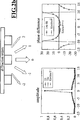
Die
Die
Die
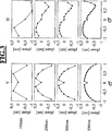
In
Für jeden Pitch kann die Phase der Wellenfront durch einen Manipulator nach einem der Sätze 1. Satz, 2. Satz oder 3. Satz bis 6. Satz korrigiert werden. Dabei ist es vorteilhaft, wenn sich dieser Manipulator wie in dem 6. Satz in einer Pupillenebene des Objektivs befindet. Im Fall der gleichzeitigen, evtl. gewichteten Korrektur mehrerer Pitches nach dem 4. Satz ist ein ortsauflösender Manipulator nach dem 6. Satz vorteilhaft, da die sich durch die Überlagerung der Phasenfehler der einzelnen Pitches ergebende Wellenfront in ihrer radialen Komponente a priori eine Vielzahl von Wendepunkten hat.For each pitch, the phase of the wavefront can be corrected by a manipulator according to one of the sentences 1st sentence, 2nd sentence or 3rd sentence to 6th sentence. It is advantageous if this manipulator is located in a pupil plane of the objective, as in the sixth movement. In the case of the simultaneous, possibly weighted correction of several pitches after the 4th sentence, a spatially resolving manipulator according to the 6th sentence is advantageous, since the wave front resulting from the superimposition of the phase errors of the individual pitches has a plurality of inflection points in its radial component a priori Has.
In
Die obige Darstellung gilt für einen fest gewählten Objektpunkt des Objektfeldes des Objektivs und ähnliche Darstellungen lassen sich für anderen Objektpunkte ableiten. Daher sind diese Darstellungen als ortsabhängig von dem abzubildenden Objektpunkt zu verstehen. Anders formuliert hat die durch die verschiedenen Pitches induzierte Wellenfrontaberration einen Feldverlauf und vorteilhafterweise wird dieser durch einen zweiten Manipulator nach dem 12. Satz korrigiert, welcher nicht in einer Pupillenebene des Objektivs steht.The above representation applies to a fixed selected object point of the object field of the lens and similar representations can be derived for other object points. Therefore, these are To understand representations as location-dependent on the object to be imaged object point. In other words, the wavefront aberration induced by the different pitches has a field profile and, advantageously, this is corrected by a second manipulator after the 12th sentence, which does not stand in a pupil plane of the objective.
Wie bereits oben dargestellt, finden sich in den durch die verschiedenen Pitches induzierten Wellenfrontaberration in erster Linie Terme, welche den Fokus beeinflussen. Man vgl. hierzu die Phasenverläufe aus der ersten Spalte von
Der Fokus zeigt sich nicht nur als Pitch-abhängig, sondern er ist auch von der abzubildenden Strukurbreite abhängig.The focus is not only pitch-dependent, but also dependent on the pattern width to be mapped.
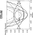
In
In
In
ZITATE ENTHALTEN IN DER BESCHREIBUNG QUOTES INCLUDE IN THE DESCRIPTION
Diese Liste der vom Anmelder aufgeführten Dokumente wurde automatisiert erzeugt und ist ausschließlich zur besseren Information des Lesers aufgenommen. Die Liste ist nicht Bestandteil der deutschen Patent- bzw. Gebrauchsmusteranmeldung. Das DPMA übernimmt keinerlei Haftung für etwaige Fehler oder Auslassungen.This list of the documents listed by the applicant has been generated automatically and is included solely for the better information of the reader. The list is not part of the German patent or utility model application. The DPMA assumes no liability for any errors or omissions.
Zitierte PatentliteraturCited patent literature
- US 20060139611 A1 [0012] US 20060139611 A1 [0012]
- US 20090034061 A1 [0012] US 20090034061 A1 [0012]
- US 20080151365 A1 [0012] US 20080151365 A1 [0012]
- US 20050088760 A1 [0013, 0017] US 20050088760 A1 [0013, 0017]
- US 200801700310 A1 [0013, 0017] US 200801700310 A1 [0013, 0017]
- EP 678768 A2 [0026] EP 678768 A2 [0026]
- EP 1670041 A1 [0026] EP 1670041 A1 [0026]
- WO 2008037496 A2 [0026, 0034] WO 2008037496 A2 [0026, 0034]
- US 20030234918 A1 [0026, 0034] US 20030234918 A1 [0026, 0034]
- US 20090257032 A1 [0026, 0034] US 20090257032 A1 [0026, 0034]
- WO 2009026970 A1 [0026, 0034] WO 2009026970 A1 [0026, 0034]
- EP 851304 A2 [0027] EP 851304 A2 [0027]
- US 20030063268 A1 [0027] US 20030063268 A1 [0027]
- US 6191898 B1 [0027] US 6191898 B1 [0027]
- WO 2007062794 A1 [0027] WO 2007062794 A1 [0027]
- DE 102005034991 A1 [0030] DE 102005034991 A1 [0030]
- US 20070165202 A1 [0030] US 20070165202 A1 [0030]
- WO 2009100856 A1 [0030] WO 2009100856 A1 [0030]
- DE 102009016 A1 [0032] DE 102009016 A1 [0032]
- WO 2009034109 A2 [0032] WO 2009034109 A2 [0032]
Zitierte Nicht-PatentliteraturCited non-patent literature
- Illumination Optics for Source-Mask Optimization, Yasushi Mizuno et al, Proc. SPIE 7640, 76401I (2010) [0006] Illumination Optics for Source-Mask Optimization, Yasushi Mizuno et al, Proc. SPIE 7640, 76401I (2010) [0006]
- Polarization-induced astigmatism caused by topographic masks, Ruoff et al, Proc SPIE 6730, 67301T (2007) [0014] Polarization-induced astigmatism caused by topographic masks, Ruoff et al, Proc. SPIE 6730, 67301T (2007) [0014]
- Handbook of Optical Systems, Singer et al (eds.), Wiley-Vch, 2005 [0014] Handbook of Optical Systems, Singer et al (eds.), Wiley-Vch, 2005. [0014]
- Mask diffraction analysis and optimization for EUV masks, Erdmann et al, Proceedings of the SPIE The International Society for Optical Engineering 2009, vol. 7271 [0018] Erdmann et al, Proceedings of the SPIE The International Society for Optical Engineering 2009, vol. 7271 [0018]
- Illumination Optics for Source-Mask Optimization, Yasushi Mizuno et al, Proc. SPIE 7640, 76401I (2010) [0030] Illumination Optics for Source-Mask Optimization, Yasushi Mizuno et al, Proc. SPIE 7640, 76401I (2010) [0030]
Claims (12)
Priority Applications (10)
| Application Number | Priority Date | Filing Date | Title |
|---|---|---|---|
| DE102010029651A DE102010029651A1 (en) | 2010-06-02 | 2010-06-02 | Method for operating a microlithographic projection exposure apparatus with correction of aberrations induced by rigorous effects of the mask |
| PCT/EP2011/054084 WO2011120821A1 (en) | 2010-03-30 | 2011-03-17 | Method for operating a projection exposure apparatus with correction of imaging aberrations induced by the mask |
| KR1020127025419A KR101518107B1 (en) | 2010-03-30 | 2011-03-17 | Method for operating a projection exposure apparatus with correction of imaging aberrations induced by the mask |
| JP2013501741A JP5768124B2 (en) | 2010-03-30 | 2011-03-17 | Method for operating a projection exposure apparatus with correction of imaging aberrations caused by a mask |
| CN201180016812.XA CN102834776B (en) | 2010-03-30 | 2011-03-17 | Method for operating a projection exposure apparatus for microlithography with correction of imaging aberrations induced by the mask |
| TW100109849A TWI435188B (en) | 2010-03-30 | 2011-03-23 | Method for operating a projection exposure apparatus for microlithography with correction of imaging aberrations induced by rigorous effects of the mask |
| US13/555,785 US9041908B2 (en) | 2010-03-30 | 2012-07-23 | Method for operating a projection exposure apparatus with correction of imaging aberrations induced by the mask |
| US14/700,973 US20150234289A1 (en) | 2010-03-30 | 2015-04-30 | Method for operating a projection exposure apparatus with correction of imaging aberrations induced by the mask |
| JP2015124720A JP6527397B2 (en) | 2010-03-30 | 2015-06-22 | Method of operating a projection exposure apparatus with correction of imaging aberrations caused by a mask |
| JP2019034562A JP2019095814A (en) | 2010-03-30 | 2019-02-27 | Method for operating projection exposure apparatus with correction of imaging aberrations induced by mask |
Applications Claiming Priority (1)
| Application Number | Priority Date | Filing Date | Title |
|---|---|---|---|
| DE102010029651A DE102010029651A1 (en) | 2010-06-02 | 2010-06-02 | Method for operating a microlithographic projection exposure apparatus with correction of aberrations induced by rigorous effects of the mask |
Publications (1)
| Publication Number | Publication Date |
|---|---|
| DE102010029651A1 true DE102010029651A1 (en) | 2011-12-08 |
Family
ID=43902677
Family Applications (1)
| Application Number | Title | Priority Date | Filing Date |
|---|---|---|---|
| DE102010029651A Ceased DE102010029651A1 (en) | 2010-03-30 | 2010-06-02 | Method for operating a microlithographic projection exposure apparatus with correction of aberrations induced by rigorous effects of the mask |
Country Status (7)
| Country | Link |
|---|---|
| US (2) | US9041908B2 (en) |
| JP (3) | JP5768124B2 (en) |
| KR (1) | KR101518107B1 (en) |
| CN (1) | CN102834776B (en) |
| DE (1) | DE102010029651A1 (en) |
| TW (1) | TWI435188B (en) |
| WO (1) | WO2011120821A1 (en) |
Families Citing this family (23)
| Publication number | Priority date | Publication date | Assignee | Title |
|---|---|---|---|---|
| DE102010061950A1 (en) * | 2010-11-25 | 2012-05-31 | Carl Zeiss Smt Gmbh | Method and device for determining the heating state of a mirror in an optical system |
| JP5940556B2 (en) | 2010-12-28 | 2016-06-29 | ユニリーバー・ナームローゼ・ベンノートシヤープ | Method for producing emulsion |
| US9410596B2 (en) | 2011-11-04 | 2016-08-09 | Honeywell International Inc. | Mounting systems for structural members, fastening assemblies thereof, and vibration isolation systems including the same |
| US9475594B2 (en) | 2012-09-25 | 2016-10-25 | Honeywell International Inc. | Launch lock assemblies with reduced preload and spacecraft isolation systems including the same |
| US9298102B2 (en) | 2013-03-13 | 2016-03-29 | Carl Zeiss Smt Gmbh | Projection lens with wavefront manipulator |
| US9651872B2 (en) | 2013-03-13 | 2017-05-16 | Carl Zeiss Smt Gmbh | Projection lens with wavefront manipulator |
| DE102013204391B3 (en) * | 2013-03-13 | 2014-05-28 | Carl Zeiss Smt Gmbh | Projection lens for imaging projection lens pattern from object plane into image plane, has field point in field plane of outgoing beam illuminating manipulator surface with sub-aperture, and manipulation system comprising manipulator |
| KR101597186B1 (en) * | 2013-06-21 | 2016-02-24 | 호야 가부시키가이샤 | Mask blank substrate, mask blank, transfer mask, manufacturing methods therefor, and manufacturing method for semiconductor device |
| WO2016012426A1 (en) | 2014-07-22 | 2016-01-28 | Carl Zeiss Smt Gmbh | Method for three-dimensionally measuring a 3d aerial image of a lithography mask |
| DE102014218474A1 (en) | 2014-09-15 | 2016-03-17 | Carl Zeiss Smt Gmbh | Projection objective, projection exposure apparatus and projection exposure method for EUV microlithography |
| WO2017147261A1 (en) * | 2016-02-24 | 2017-08-31 | Kla-Tencor Corporation | Accuracy improvements in optical metrology |
| DE102016205617A1 (en) | 2016-04-05 | 2017-10-05 | Carl Zeiss Smt Gmbh | Projection exposure method and projection exposure apparatus |
| DE102016209616A1 (en) * | 2016-06-01 | 2017-12-07 | Carl Zeiss Smt Gmbh | A method and apparatus for predicting the imaging result obtained with a mask when performing a lithographic process |
| DE102016212477A1 (en) | 2016-07-08 | 2018-01-11 | Carl Zeiss Smt Gmbh | Measuring method and measuring system for the interferometric measurement of the imaging quality of an optical imaging system |
| KR20210018967A (en) * | 2016-07-11 | 2021-02-18 | 에이에스엠엘 네델란즈 비.브이. | Method and apparatus for determining a fingerprint of a performance parameter |
| DE102016221261A1 (en) * | 2016-10-28 | 2018-05-03 | Carl Zeiss Smt Gmbh | Process for the microlithographic production of microstructured components |
| US10162257B2 (en) | 2016-12-15 | 2018-12-25 | Taiwan Semiconductor Manufacturing Co., Ltd. | Extreme ultraviolet lithography system, device, and method for printing low pattern density features |
| DE102017115262B9 (en) | 2017-07-07 | 2021-05-27 | Carl Zeiss Smt Gmbh | Method for characterizing a mask for microlithography |
| DE102017115365B4 (en) * | 2017-07-10 | 2020-10-15 | Carl Zeiss Smt Gmbh | Semiconductor lithography mask inspection device and process |
| DE102018202637B4 (en) * | 2018-02-21 | 2021-09-23 | Carl Zeiss Smt Gmbh | Method for determining a focus position of a lithography mask and metrology system for carrying out such a method |
| US11429027B2 (en) | 2018-08-17 | 2022-08-30 | Taiwan Semiconductor Manufacturing Co., Ltd. | Photolithography method and apparatus |
| CN113767337B (en) * | 2019-04-30 | 2024-04-16 | Asml荷兰有限公司 | Method and apparatus for lithographic imaging |
| DE102020209784A1 (en) * | 2020-08-04 | 2022-02-10 | Carl Zeiss Smt Gmbh | METHOD OF MANUFACTURE OR ADJUSTMENT OF A PROJECTION EXPOSURE EQUIPMENT |
Citations (23)
| Publication number | Priority date | Publication date | Assignee | Title |
|---|---|---|---|---|
| EP0678768A2 (en) | 1994-04-22 | 1995-10-25 | Canon Kabushiki Kaisha | Projection exposure apparatus and microdevice manufacturing method |
| US5673103A (en) * | 1993-09-24 | 1997-09-30 | Kabushiki Kaisha Toshiba | Exposure apparatus and method |
| EP0851304A2 (en) | 1996-12-28 | 1998-07-01 | Canon Kabushiki Kaisha | Projection exposure apparatus and device manufacturing method |
| US6191898B1 (en) | 1999-01-15 | 2001-02-20 | Carl-Zeiss-Stiftung | Optical imaging device, particularly an objective, with at least one optical element |
| US20030063268A1 (en) | 2001-09-05 | 2003-04-03 | Bernhard Kneer | Projection exposure system |
| DE10209016A1 (en) | 2002-02-28 | 2003-09-11 | Alen Jambrecina | Ultrasonic probe head, e.g. for medical examinations, incorporates a couplant dispensing device so that there is always sufficient couplant available to ensure effective coupling of the sound waves to the examination object |
| US20030234918A1 (en) | 2002-06-20 | 2003-12-25 | Nikon Corporation | Adjustable soft mounts in kinematic lens mounting system |
| US20050088760A1 (en) | 1998-05-05 | 2005-04-28 | Carl Zeiss Smt Ag | Illumination system particularly for microlithography |
| DE102005034991A1 (en) | 2004-09-08 | 2006-04-13 | Carl Zeiss Smt Ag | System for radial redistribution of light intensities in an illumination system of a microlithographic projection system has a zoom objective either side of conversion elements |
| EP1670041A1 (en) | 2003-08-28 | 2006-06-14 | Nikon Corporation | Exposure method and apparatus, and device manufacturing method |
| US20060139611A1 (en) | 2004-12-28 | 2006-06-29 | Asml Netherlands B.V. | Polarized radiation in lithographic apparatus and device manufacturing method |
| WO2007062794A1 (en) | 2005-12-03 | 2007-06-07 | Carl Zeiss Smt Ag | Objective, in particular projection objective for semiconductor lithography |
| US20070165202A1 (en) | 2003-09-12 | 2007-07-19 | Carl Zeiss Smt Ag | Illumination system for a microlithography projection exposure installation |
| US20080043236A1 (en) * | 2004-08-09 | 2008-02-21 | Nikon Corporation | Optical Property Measurement Apparatus and Optical Property Measurement Method, Exposure Apparatus and Exposure Method, and Device Manufacturing Method |
| WO2008037496A2 (en) | 2006-09-28 | 2008-04-03 | Carl Zeiss Smt Ag | Projection objective for a microlithography apparatus with improved imaging properties and method for improving the imaging properties of the projection objective |
| US20080151365A1 (en) | 2004-01-14 | 2008-06-26 | Carl Zeiss Smt Ag | Catadioptric projection objective |
| US20080170310A1 (en) | 2007-01-17 | 2008-07-17 | Carl Zeiss Smt Ag | Imaging optical system |
| US20090034061A1 (en) | 2004-05-17 | 2009-02-05 | Aurelian Dodoc | Catadioptric projection objective with intermediate images |
| WO2009026970A1 (en) | 2007-08-24 | 2009-03-05 | Carl Zeiss Smt Ag | Controllable optical element and method for operating an optical element with thermal actuators and projection exposure apparatus for semiconductor lithography |
| WO2009034109A2 (en) | 2007-09-14 | 2009-03-19 | Carl Zeiss Smt Ag | Illumination system of a microlithographic projection exposure apparatus |
| US20090086185A1 (en) * | 2007-10-01 | 2009-04-02 | Canon Kabushiki Kaisha | Illumination optical system, exposure apparatus, and device manufacturing method |
| WO2009100856A1 (en) | 2008-02-15 | 2009-08-20 | Carl Zeiss Smt Ag | Facet mirror for use in a projection exposure apparatus for microlithography |
| US20090257032A1 (en) | 2006-09-21 | 2009-10-15 | Carl Zeiss Smt Ag | Optical element and method |
Family Cites Families (14)
| Publication number | Priority date | Publication date | Assignee | Title |
|---|---|---|---|---|
| JP2000091209A (en) * | 1998-09-14 | 2000-03-31 | Nikon Corp | Aligner and manufacture thereof, and device manufacturing method |
| US6816302B2 (en) | 1998-03-02 | 2004-11-09 | Micronic Laser Systems Ab | Pattern generator |
| SE9800665D0 (en) | 1998-03-02 | 1998-03-02 | Micronic Laser Systems Ab | Improved method for projection printing using a micromirror SLM |
| US7042550B2 (en) * | 2002-11-28 | 2006-05-09 | Asml Netherlands B.V. | Device manufacturing method and computer program |
| US7403264B2 (en) * | 2004-07-08 | 2008-07-22 | Asml Netherlands B.V. | Lithographic projection apparatus and a device manufacturing method using such lithographic projection apparatus |
| KR100614651B1 (en) | 2004-10-11 | 2006-08-22 | 삼성전자주식회사 | Apparatus And Method For Pattern Exposure, Photomask Used Therefor, Design Method For The Photomask, Illuminating System Therefor and Implementing Method For The Illuminating System |
| JP2006173305A (en) * | 2004-12-15 | 2006-06-29 | Canon Inc | Aligner and its method, and device manufacturing method |
| JP4753009B2 (en) * | 2005-05-24 | 2011-08-17 | 株式会社ニコン | Measuring method, exposure method, and exposure apparatus |
| JP4701030B2 (en) * | 2005-07-22 | 2011-06-15 | キヤノン株式会社 | Exposure apparatus, setting method for setting exposure parameters, exposure method, device manufacturing method, and program |
| EP1795967B1 (en) * | 2005-12-09 | 2010-05-05 | Imec | Methods and devices for lithography |
| JP4793683B2 (en) * | 2006-01-23 | 2011-10-12 | 株式会社ニコン | Calculation method, adjustment method, exposure method, image forming state adjustment system, and exposure apparatus |
| JP2008041710A (en) * | 2006-08-01 | 2008-02-21 | Fujitsu Ltd | Lighting optical device, exposure method, and design method |
| DE102009016063A1 (en) | 2008-05-21 | 2009-11-26 | Carl Zeiss Smt Ag | Micro lithographic projection exposure method for manufacturing e.g. LCD, involves projecting mask structure on region of layer using projection exposure apparatus, where regions are arranged in parts in optical path of illumination device |
| JP5078764B2 (en) | 2008-06-10 | 2012-11-21 | キヤノン株式会社 | Computer generated hologram, exposure apparatus and device manufacturing method |
-
2010
- 2010-06-02 DE DE102010029651A patent/DE102010029651A1/en not_active Ceased
-
2011
- 2011-03-17 KR KR1020127025419A patent/KR101518107B1/en active IP Right Grant
- 2011-03-17 WO PCT/EP2011/054084 patent/WO2011120821A1/en active Application Filing
- 2011-03-17 CN CN201180016812.XA patent/CN102834776B/en active Active
- 2011-03-17 JP JP2013501741A patent/JP5768124B2/en active Active
- 2011-03-23 TW TW100109849A patent/TWI435188B/en active
-
2012
- 2012-07-23 US US13/555,785 patent/US9041908B2/en active Active
-
2015
- 2015-04-30 US US14/700,973 patent/US20150234289A1/en not_active Abandoned
- 2015-06-22 JP JP2015124720A patent/JP6527397B2/en active Active
-
2019
- 2019-02-27 JP JP2019034562A patent/JP2019095814A/en active Pending
Patent Citations (23)
| Publication number | Priority date | Publication date | Assignee | Title |
|---|---|---|---|---|
| US5673103A (en) * | 1993-09-24 | 1997-09-30 | Kabushiki Kaisha Toshiba | Exposure apparatus and method |
| EP0678768A2 (en) | 1994-04-22 | 1995-10-25 | Canon Kabushiki Kaisha | Projection exposure apparatus and microdevice manufacturing method |
| EP0851304A2 (en) | 1996-12-28 | 1998-07-01 | Canon Kabushiki Kaisha | Projection exposure apparatus and device manufacturing method |
| US20050088760A1 (en) | 1998-05-05 | 2005-04-28 | Carl Zeiss Smt Ag | Illumination system particularly for microlithography |
| US6191898B1 (en) | 1999-01-15 | 2001-02-20 | Carl-Zeiss-Stiftung | Optical imaging device, particularly an objective, with at least one optical element |
| US20030063268A1 (en) | 2001-09-05 | 2003-04-03 | Bernhard Kneer | Projection exposure system |
| DE10209016A1 (en) | 2002-02-28 | 2003-09-11 | Alen Jambrecina | Ultrasonic probe head, e.g. for medical examinations, incorporates a couplant dispensing device so that there is always sufficient couplant available to ensure effective coupling of the sound waves to the examination object |
| US20030234918A1 (en) | 2002-06-20 | 2003-12-25 | Nikon Corporation | Adjustable soft mounts in kinematic lens mounting system |
| EP1670041A1 (en) | 2003-08-28 | 2006-06-14 | Nikon Corporation | Exposure method and apparatus, and device manufacturing method |
| US20070165202A1 (en) | 2003-09-12 | 2007-07-19 | Carl Zeiss Smt Ag | Illumination system for a microlithography projection exposure installation |
| US20080151365A1 (en) | 2004-01-14 | 2008-06-26 | Carl Zeiss Smt Ag | Catadioptric projection objective |
| US20090034061A1 (en) | 2004-05-17 | 2009-02-05 | Aurelian Dodoc | Catadioptric projection objective with intermediate images |
| US20080043236A1 (en) * | 2004-08-09 | 2008-02-21 | Nikon Corporation | Optical Property Measurement Apparatus and Optical Property Measurement Method, Exposure Apparatus and Exposure Method, and Device Manufacturing Method |
| DE102005034991A1 (en) | 2004-09-08 | 2006-04-13 | Carl Zeiss Smt Ag | System for radial redistribution of light intensities in an illumination system of a microlithographic projection system has a zoom objective either side of conversion elements |
| US20060139611A1 (en) | 2004-12-28 | 2006-06-29 | Asml Netherlands B.V. | Polarized radiation in lithographic apparatus and device manufacturing method |
| WO2007062794A1 (en) | 2005-12-03 | 2007-06-07 | Carl Zeiss Smt Ag | Objective, in particular projection objective for semiconductor lithography |
| US20090257032A1 (en) | 2006-09-21 | 2009-10-15 | Carl Zeiss Smt Ag | Optical element and method |
| WO2008037496A2 (en) | 2006-09-28 | 2008-04-03 | Carl Zeiss Smt Ag | Projection objective for a microlithography apparatus with improved imaging properties and method for improving the imaging properties of the projection objective |
| US20080170310A1 (en) | 2007-01-17 | 2008-07-17 | Carl Zeiss Smt Ag | Imaging optical system |
| WO2009026970A1 (en) | 2007-08-24 | 2009-03-05 | Carl Zeiss Smt Ag | Controllable optical element and method for operating an optical element with thermal actuators and projection exposure apparatus for semiconductor lithography |
| WO2009034109A2 (en) | 2007-09-14 | 2009-03-19 | Carl Zeiss Smt Ag | Illumination system of a microlithographic projection exposure apparatus |
| US20090086185A1 (en) * | 2007-10-01 | 2009-04-02 | Canon Kabushiki Kaisha | Illumination optical system, exposure apparatus, and device manufacturing method |
| WO2009100856A1 (en) | 2008-02-15 | 2009-08-20 | Carl Zeiss Smt Ag | Facet mirror for use in a projection exposure apparatus for microlithography |
Non-Patent Citations (4)
| Title |
|---|
| Handbook of Optical Systems, Singer et al (eds.), Wiley-Vch, 2005 |
| Illumination Optics for Source-Mask Optimization, Yasushi Mizuno et al, Proc. SPIE 7640, 76401I (2010) |
| Mask diffraction analysis and optimization for EUV masks, Erdmann et al, Proceedings of the SPIE The International Society for Optical Engineering 2009, vol. 7271 |
| Polarization-induced astigmatism caused by topographic masks, Ruoff et al, Proc SPIE 6730, 67301T (2007) |
Also Published As
| Publication number | Publication date |
|---|---|
| US9041908B2 (en) | 2015-05-26 |
| US20120320358A1 (en) | 2012-12-20 |
| TW201202866A (en) | 2012-01-16 |
| CN102834776B (en) | 2015-05-06 |
| KR20130019384A (en) | 2013-02-26 |
| JP5768124B2 (en) | 2015-08-26 |
| JP2015222428A (en) | 2015-12-10 |
| US20150234289A1 (en) | 2015-08-20 |
| JP2013524497A (en) | 2013-06-17 |
| JP6527397B2 (en) | 2019-06-05 |
| CN102834776A (en) | 2012-12-19 |
| TWI435188B (en) | 2014-04-21 |
| JP2019095814A (en) | 2019-06-20 |
| KR101518107B1 (en) | 2015-05-06 |
| WO2011120821A1 (en) | 2011-10-06 |
Similar Documents
| Publication | Publication Date | Title |
|---|---|---|
| DE102010029651A1 (en) | Method for operating a microlithographic projection exposure apparatus with correction of aberrations induced by rigorous effects of the mask | |
| DE102018210315B4 (en) | Method for detecting a structure of a lithography mask and device for carrying out the method | |
| DE102012202057B4 (en) | Projection objective for EUV microlithography, foil element and method for producing a projection objective with foil element | |
| DE60209652T2 (en) | Method for measuring the aberration of a lithographic projection system | |
| DE102013204391B3 (en) | Projection lens for imaging projection lens pattern from object plane into image plane, has field point in field plane of outgoing beam illuminating manipulator surface with sub-aperture, and manipulation system comprising manipulator | |
| DE102008064504B4 (en) | Projection exposure method and projection exposure apparatus for microlithography | |
| DE102009041405B4 (en) | Mask inspection microscope with variable lighting setting | |
| EP3256835A1 (en) | Test device and method for testing a mirror | |
| DE10258715B4 (en) | Method for producing an optical imaging system | |
| DE102015206448B4 (en) | Control device for controlling at least one manipulator of a projection objective, adjusting device and method for controlling at least one manipulator | |
| DE102011080437A1 (en) | Imaging optical system for microlithography | |
| DE102015209051B4 (en) | Projection objective with wavefront manipulator as well as projection exposure method and projection exposure apparatus | |
| DE102014218474A1 (en) | Projection objective, projection exposure apparatus and projection exposure method for EUV microlithography | |
| DE102009048553A1 (en) | Catadioptric projection objective with deflecting mirrors and projection exposure method | |
| EP1746463A2 (en) | Method for correcting a lithographic projection objective and projection objective of such a kind | |
| DE102010047051A1 (en) | Method for determining the position of a structure within an image and position measuring device for carrying out the method | |
| DE102012207377A1 (en) | Illumination optics and optical system for EUV projection lithography | |
| DE102017209440A1 (en) | Projection exposure method and projection exposure apparatus for microlithography | |
| DE102012212757A1 (en) | METHOD FOR OPERATING A MICROLITHOGRAPHIC PROJECTION EXPOSURE PLANT | |
| DE102010038748A1 (en) | Method for producing a mirror with at least two mirror surfaces, mirrors of a microlithography projection exposure apparatus and projection exposure apparatus | |
| DE102015218917A1 (en) | Method for determining a position of a structural element on a mask and position measuring device for carrying out the method | |
| DE102017208340A1 (en) | Projection exposure method and projection objective with adjustment of the pupil transmission | |
| DE102012202536A1 (en) | Projection exposure method and projection exposure apparatus for microlithography | |
| WO2019101419A1 (en) | Method and device for calibrating a diffractive measuring structure | |
| DE102010041746A1 (en) | Projection exposure apparatus of EUV microlithography and method for microlithographic exposure |
Legal Events
| Date | Code | Title | Description |
|---|---|---|---|
| R002 | Refusal decision in examination/registration proceedings | ||
| R003 | Refusal decision now final |
Effective date: 20130215 |