DE102010015552B4 - Machine for the production of three-day pasta with exchangeable horizontal and vertical material feed - Google Patents
Machine for the production of three-day pasta with exchangeable horizontal and vertical material feed Download PDFInfo
- Publication number
- DE102010015552B4 DE102010015552B4 DE201010015552 DE102010015552A DE102010015552B4 DE 102010015552 B4 DE102010015552 B4 DE 102010015552B4 DE 201010015552 DE201010015552 DE 201010015552 DE 102010015552 A DE102010015552 A DE 102010015552A DE 102010015552 B4 DE102010015552 B4 DE 102010015552B4
- Authority
- DE
- Germany
- Prior art keywords
- material guide
- combining
- tube
- feed hopper
- material feed
- Prior art date
- Legal status (The legal status is an assumption and is not a legal conclusion. Google has not performed a legal analysis and makes no representation as to the accuracy of the status listed.)
- Expired - Fee Related
Links
- 239000000463 material Substances 0.000 title claims abstract description 181
- 235000015927 pasta Nutrition 0.000 title claims abstract description 16
- 238000004519 manufacturing process Methods 0.000 title abstract description 5
- 238000003756 stirring Methods 0.000 claims description 8
- 238000007142 ring opening reaction Methods 0.000 claims description 3
- 230000000694 effects Effects 0.000 claims description 2
- 241000237858 Gastropoda Species 0.000 description 2
- 235000013305 food Nutrition 0.000 description 2
- 239000012467 final product Substances 0.000 description 1
- 239000000796 flavoring agent Substances 0.000 description 1
- 235000019634 flavors Nutrition 0.000 description 1
- 239000007858 starting material Substances 0.000 description 1
Images

Classifications
-
- A—HUMAN NECESSITIES
- A21—BAKING; EDIBLE DOUGHS
- A21C—MACHINES OR EQUIPMENT FOR MAKING OR PROCESSING DOUGHS; HANDLING BAKED ARTICLES MADE FROM DOUGH
- A21C11/00—Other machines for forming the dough into its final shape before cooking or baking
- A21C11/16—Extruding machines
- A21C11/163—Applying co-extrusion, i.e. extruding two or more plastic substances simultaneously, e.g. for making filled dough products; Making products from two or more different substances supplied to the extruder
Landscapes
- Life Sciences & Earth Sciences (AREA)
- Engineering & Computer Science (AREA)
- Food Science & Technology (AREA)
- Manufacturing And Processing Devices For Dough (AREA)
Abstract
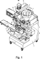
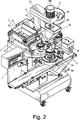
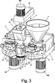
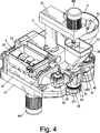
Maschine zur Erzeugung von dreilägigen Teigwaren mit austauschbarer liegender und stehender Materialzuführung, umfassend einen Getriebekasten (11) auf einem Maschinengehäuse (1), unter dem zwei Antriebsmotoren (M1), (M2) vorgesehen sind und der auf der Oberseite einen Oberdeckel (12) aufweist und im Inneren eine Vielzahl von Getrieberädern und Getriebeelementen aufnimmt, die mit den Antriebsmotoren (M1), (M2) verbunden sind, wobei der Oberdeckel (12) an der Vorderseite einen Schwalbenschwanzvorsprung (14) besitzt, eine Säule (2), die in der Mitte auf dem Oberdeckel (12) angeordnet ist und auf der ein Balken (21) vorgesehen ist, der mit einem Ende einen Motor (M3) trägt, wobei der Motor (M3) mit einer Schnecke (22) verbunden ist, die sich nach unten erstreckt und in einen mittleren Materialzuführungstrichter (13) hineinragt, und wobei unter der Säule (2) ein Antriebsmotor (M4) angeordnet ist, einen liegenden Materialzuführungsbehälter (3), der an einer Seite auf dem Oberdeckel (12) angeordnet ist und in dem zwei Schnecken (31), (32) vorgesehen sind, die mit dem Antriebsmotor (M1) verbunden sind und von diesem drehangetrieben werden, einen stehenden Materialzuführungstrichter (4), der an der anderen Seite auf dem Oberdeckel (12) angeordnet ist und in dem eine Schnecke (41) vorgesehen ist, die mit dem Antriebsmotor (M2) verbunden ist und von diesem drehangetrieben wird, zwei Materialführungen (34), (42), die am Eingang mit dem liegenden Materialzuführungsbehälter (3) und dem stehenden Materialzuführungstrichter (4) verbunden sind, wobei die Ausgangsrohre (37), (45) der Materialführungen (34), (42) mit einer mittleren kombinierenden Materialführung (5) verbunden sind, und eine kombinierende Materialführung (5), die durch ein Rohr gebildet ist und eine obere Deckplatte (51) aufweist, auf der ein mittlerer Materialzuführungstrichter (13) angeordnet ist, wobei an der Außenseite der kombinierenden Materialführungen (5) ein Paar Schwalbenschwanznuten (52), (53) vorgesehen sind, wobei in der kombinierenden Materialführung (5) ein äußeres Materialführungsrohr (54) befestigt ist, das für die Ausgangsrohre (37), (45) der Materialführungen (34), (42) ein Durchgangsloch (55) besitzt, das mit dem Ausgangsrohr (37) oder (45) verbunden werden kann, wobei in dem äußeren Materialführungsrohr (54) ein inneres Materialführungsrohr (56) aufgenommen ist, dessen Innenraum (57) mit der Öffnung in der Unterseite des mittleren Materialzuführungstrichters (13) verbunden ist ...Machine for the production of three-layer pasta with exchangeable horizontal and vertical material feed, comprising a gear box (11) on a machine housing (1), under which two drive motors (M1), (M2) are provided and which has an upper lid (12) on the top and inside a plurality of gears and gear elements which are connected to the drive motors (M1), (M2), wherein the top cover (12) has a dovetail projection (14) on the front, a column (2), which in the Center on the upper cover (12) is arranged and on which a beam (21) is provided, one end of which carries a motor (M3), the motor (M3) being connected to a worm (22) which extends downwards extends and protrudes into a central material feed hopper (13), and wherein a drive motor (M4) is arranged under the column (2), a lying material feed container (3) which is attached to one side on the upper cover (12) is arranged and in which two screws (31), (32) are provided which are connected to the drive motor (M1) and are driven in rotation by this, a standing material feed hopper (4), which is on the other side on the upper cover (12) is arranged and in which a screw (41) is provided, which is connected to the drive motor (M2) and is driven in rotation by this, two material guides (34), (42), which at the entrance to the lying material feed container (3) and the standing material feed hopper (4) are connected, the output pipes (37), (45) of the material guides (34), (42) are connected to a central combining material guide (5), and a combining material guide (5), which is connected by a tube and has an upper cover plate (51) on which a central material feed hopper (13) is arranged, a pair of dovetail grooves (52), (53) being provided on the outside of the combining material guides (5) nd, wherein in the combining material guide (5) an outer material guide tube (54) is attached, which has a through hole (55) for the output tubes (37), (45) of the material guides (34), (42), which with the output tube (37) or (45), with an inner material guide tube (56) being received in the outer material guide tube (54), the interior space (57) of which is connected to the opening in the underside of the central material feed hopper (13).
Description
Technisches GebietTechnical area
Die Erfindung betrifft eine Maschine zur Erzeugung von dreilägigen Teigwaren mit austauschbarer liegender und stehender Materialzuführung, die drei Materialzuführungsorgane aufweist, durch die drei unterschiedliche Materialien, d. h. das äußere, mittlere und innere Material zugeführt werden können, wodurch eine dreilägige gefüllte Teigware erzeugt werden kann. Das Merkmal der Erfindung besteht darin, dass durch eine Richtungsänderung um 180° einer mittleren kombinierenden Materialführung das äußere und mittlere Material gegeneinander ausgetauscht werden können, ohne das Material in dem liegenden Materialzuführungsbehälter und dem stehenden Material zuführungstrichter gegeneinander auszutauschen.The invention relates to a machine for producing three-day pasta with interchangeable horizontal and vertical material supply, which has three material feed members, by the three different materials, d. H. the outer, middle and inner material can be supplied, whereby a three-day filled pasta can be produced. The feature of the invention is that by changing the direction by 180 ° of a central combining material guide the outer and middle material can be exchanged with each other, without exchanging the material in the horizontal material supply container and the standing material feed hopper against each other.
Stand der TechnikState of the art
Die gefüllten Teigwaren sind überlichweise zweilägig und weisen eine Teigplatte und eine Teigfüllung auf. Durch die Teigfüllung wird der Geschmack verbessert. Dafür besitzt die Herstellungsmaschine dieser Teigwaren zwei liegende oder stehende Materialzuführungsbehälter, in denen Schnecken vorgesehen sind, um die Materialien für die Teigplatte und die Teigfüllung zu fördern.The stuffed pasta is over two days and has a dough sheet and a dough filling. The dough filling improves the taste. Therefore, the making machine of this pasta has two lying or standing material feed containers in which screws are provided to convey the materials for the dough sheet and dough filling.
Um den Geschmack weiter zu erhöhen, werden die dreilägign Teigwaren entwickelt, die eine Teigplatte und zwei unterschiedliche Teigfüllungen aufweisen. Die Herstellungsmaschine dieser Teigwaren besitzt einen stehenden Materialzuführungsbehälter für das innere Material und zwei liegende oder stehende Materialzuführungsbehälter für das mittlere und äußere Material.To further increase the flavor, the dreilägign pasta is developed which has a dough sheet and two different dough fillings. The manufacturing machine of this pasta has a standing material supply container for the inner material and two lying or standing material supply container for the middle and outer material.
Die zweilägigen oder dreilägigen Teigwaren weisen ein äußeres, mittleres und/oder inneres Material, die unterschiedliche Eigenschaften, wie Weichheit oder Zähigkeit, besitzen. Wenn ihre Materialzuführungsbehälter gleich aufgebaut sind, können die Materialien jedoch nicht gleichmäßig zugeführt werden.The two-or three-day pasta has an outer, middle and / or inner material that has different properties, such as softness or toughness. However, if their material supply containers are the same, the materials can not be uniformly supplied.
In der
In der
Aufgabe der ErfindungObject of the invention
Der Erfindung liegt die Aufgabe zugrunde, eine Maschine zur Erzeugung von dreilägigen Teigwaren mit austauschbarer liegender und stehender Materialzuführung zu schaffen, die die Nachteile der herkömmlichen Lösungen überwinden kann.The invention has for its object to provide a machine for the production of three-day pasta with interchangeable horizontal and vertical material supply, which can overcome the disadvantages of conventional solutions.
Diese Aufgabe wird durch die erfindungsgemäße Maschine zur Erzeugung von dreilägigen Teigwaren mit austauschbarer liegender und stehender Materialzuführung gelöst, die die folgenden Merkmale aufweist:
- 1. für das äußere und das innere (mittlere) Material sind ein liegender Materialzuführungsbehälter und ein stehender Materialzuführungstrichter vorgesehen;
- 2. eine mittlere kombinierende Materialführung ist mit dem liegenden Materialzuführungsbehälter und dem stehendem Materialzuführungstrichter verbunden und gestattet eine Richtungsänderung von 180°, wodurch das äußere und mittlere Material gegeneinander ausgetauscht werden können, ohne das Material in dem liegenden Materialzuführungsbehälter und dem stehenden Materialzuführungstrichter gegeneinander auszutauschen;
- 3. der liegende Materialzuführungsbehälter weist im Inneren zwei Schnecken und am Ende eine druckerhöhte Materialrührstange auf, wobei die Schnecken und die druckerhöhte Materialrührstange separat drehangetrieben werden, so dass das Material gleichmäßig geführt werden kann;
- 4. zwischen dem liegenden Materialzuführungsbehälter und dem mittleren kombinierenden Materialführung sowie zwischen dem stehendem Materialzuführungstrichter und dem mittleren kombinierenden Materialführung sind eine linke und rechte Materialführung vorgesehen, die jeweils eine Materialrührstange aufweisen, wodurch die Materialien aus dem liegenden Materialzuführungsbehälter und dem stehendem Materialzuführungstrichter gleichmäßig in die mittlere kombinierenden Materialführung geführt werden.
- 1. for the outer and the inner (middle) material, a horizontal material supply container and a stationary material supply funnel are provided;
- 2. a central combining material guide is connected to the horizontal material supply container and the stationary material supply funnel and allows a 180 ° change of direction whereby the outer and middle materials can be interchanged without interchanging the material in the horizontal material supply container and the stationary material supply funnel;
- 3. The lying material supply container has inside two worms and at the end of a pressure-elevated Materialrührstange, wherein the screws and the pressure-elevated Materialrührstange be rotated separately, so that the material can be smoothly guided;
- 4. Between the horizontal material supply container and the middle combining material guide and between the stationary material supply funnel and the central combining material guide a left and right material guide are provided, each having a Materialrührstange, whereby the materials from the horizontal material supply container and the stationary material supply funnel evenly into the middle be performed combining material guide.
Kurze Beschreibung der Zeichnungen Brief description of the drawings
Wege zur Ausführung der ErfindungWays to carry out the invention
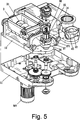
Wie aus den
Wie aus den
Die druckerhöhte Materialrührstange (
In dem stehenden Materialzuführungstrichter (
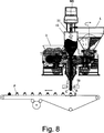
Wie aus den
Die Ausgangsrohre (
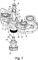
Wie aus
Auf der Unterseite der kombinierenden Materialführung (
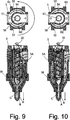
Wie aus den
Claims (5)
Priority Applications (1)
| Application Number | Priority Date | Filing Date | Title |
|---|---|---|---|
| DE201010015552 DE102010015552B4 (en) | 2010-04-15 | 2010-04-15 | Machine for the production of three-day pasta with exchangeable horizontal and vertical material feed |
Applications Claiming Priority (1)
| Application Number | Priority Date | Filing Date | Title |
|---|---|---|---|
| DE201010015552 DE102010015552B4 (en) | 2010-04-15 | 2010-04-15 | Machine for the production of three-day pasta with exchangeable horizontal and vertical material feed |
Publications (2)
| Publication Number | Publication Date |
|---|---|
| DE102010015552A1 DE102010015552A1 (en) | 2011-10-20 |
| DE102010015552B4 true DE102010015552B4 (en) | 2014-05-22 |
Family
ID=44730673
Family Applications (1)
| Application Number | Title | Priority Date | Filing Date |
|---|---|---|---|
| DE201010015552 Expired - Fee Related DE102010015552B4 (en) | 2010-04-15 | 2010-04-15 | Machine for the production of three-day pasta with exchangeable horizontal and vertical material feed |
Country Status (1)
| Country | Link |
|---|---|
| DE (1) | DE102010015552B4 (en) |
Families Citing this family (6)
| Publication number | Priority date | Publication date | Assignee | Title |
|---|---|---|---|---|
| CN106172575A (en) * | 2016-08-31 | 2016-12-07 | 上海沃敉奥机电设备有限公司 | Faric coincidence arrangement |
| CN109619639B (en) * | 2018-12-29 | 2020-10-13 | 南京信息职业技术学院 | Four seasons fortune bag auxiliary processing equipment |
| CN111557320A (en) * | 2020-06-30 | 2020-08-21 | 杨奎 | Multi-layer sandwich product processing machine |
| CN112655729B (en) * | 2020-11-30 | 2022-05-03 | 四川省成都红灯笼食品有限公司 | Food processing equipment and use method thereof |
| CN113400465B (en) * | 2021-07-05 | 2022-06-24 | 江西华翔建筑有限责任公司 | Concrete mixing equipment for construction |
| CN114451434B (en) * | 2022-03-09 | 2023-01-13 | 黄河水利职业技术学院 | A fully automatic stuffing machine for food engineering |
Citations (2)
| Publication number | Priority date | Publication date | Assignee | Title |
|---|---|---|---|---|
| DE10361607A1 (en) * | 2003-10-02 | 2005-04-28 | Robert Ou-Young | Device for producing multi-layer food |
| DE10342820B4 (en) * | 2003-08-18 | 2008-11-27 | Lien-Fu Luchow Huang | Device for forming three-layered foods |
-
2010
- 2010-04-15 DE DE201010015552 patent/DE102010015552B4/en not_active Expired - Fee Related
Patent Citations (2)
| Publication number | Priority date | Publication date | Assignee | Title |
|---|---|---|---|---|
| DE10342820B4 (en) * | 2003-08-18 | 2008-11-27 | Lien-Fu Luchow Huang | Device for forming three-layered foods |
| DE10361607A1 (en) * | 2003-10-02 | 2005-04-28 | Robert Ou-Young | Device for producing multi-layer food |
Also Published As
| Publication number | Publication date |
|---|---|
| DE102010015552A1 (en) | 2011-10-20 |
Similar Documents
| Publication | Publication Date | Title |
|---|---|---|
| DE102010015552B4 (en) | Machine for the production of three-day pasta with exchangeable horizontal and vertical material feed | |
| AT503348B1 (en) | DEVICE FOR PRODUCING FOOD PRODUCTS WITH INNER FILLING AND OUTER PACK | |
| CH644993A5 (en) | METHOD AND ARRANGEMENT FOR THE CONTINUOUS PRODUCTION OF A TRAIN FROM FOOD LAYERS. | |
| EP1515611B1 (en) | Method and device for dosing and introducing ingredients into a kneading machine | |
| DE10342820B4 (en) | Device for forming three-layered foods | |
| EP2230064A1 (en) | Twin screw extruder for ceramic masses | |
| DE885308C (en) | Extrusion press | |
| DE2228902A1 (en) | DEVICE FOR THE PRODUCTION OF COMPRESSED BLOCKS FROM A FLOUR PRODUCT | |
| EP3346846A1 (en) | Dough processing machine | |
| EP2941962A1 (en) | Confectionery mass dosing unit with a reversibly driven rotary piston | |
| DE2038577A1 (en) | Method and device for producing resin-bonded casting cores | |
| DE202011005472U1 (en) | Device for extruding food masses | |
| EP0182014A1 (en) | Process for continuously treating material for electrodes and device for performing the process | |
| DE624839C (en) | Machine for the production of pasta with kneading and pressing screw | |
| EP1736055A2 (en) | Apparatus for making dough pockets. | |
| DE69807553T2 (en) | Device for manufacturing ceramic objects | |
| DE867797C (en) | Continuous press with two pressure screws with reversed direction of rotation | |
| DE855017C (en) | Device for kneading butter, margarine or similar doughy masses | |
| DE2102349C3 (en) | Device for the production of frothy whipped cream | |
| AT60210B (en) | Machine for mixing, shaping and cutting dough. | |
| DE816170C (en) | Device for making butter | |
| DE506136C (en) | Method and apparatus for making dough from unmilled, softened grain | |
| DE263239C (en) | ||
| DE1052923B (en) | Dough kneading machine with pressing device | |
| DE1087399B (en) | Process for the production of portioned cheese mass and device for carrying out the same |
Legal Events
| Date | Code | Title | Description |
|---|---|---|---|
| R016 | Response to examination communication | ||
| R016 | Response to examination communication | ||
| R018 | Grant decision by examination section/examining division | ||
| R119 | Application deemed withdrawn, or ip right lapsed, due to non-payment of renewal fee | ||
| R119 | Application deemed withdrawn, or ip right lapsed, due to non-payment of renewal fee |
Effective date: 20141101 |