DE102010013552B4 - Rack and pinion bushing and steering device of the rack and pinion type having the rack and pinion bushing for a vehicle - Google Patents
Rack and pinion bushing and steering device of the rack and pinion type having the rack and pinion bushing for a vehicle Download PDFInfo
- Publication number
- DE102010013552B4 DE102010013552B4 DE102010013552.6A DE102010013552A DE102010013552B4 DE 102010013552 B4 DE102010013552 B4 DE 102010013552B4 DE 102010013552 A DE102010013552 A DE 102010013552A DE 102010013552 B4 DE102010013552 B4 DE 102010013552B4
- Authority
- DE
- Germany
- Prior art keywords
- rack
- diameter
- peripheral surface
- socket body
- elastic member
- Prior art date
- Legal status (The legal status is an assumption and is not a legal conclusion. Google has not performed a legal analysis and makes no representation as to the accuracy of the status listed.)
- Active
Links
- 230000002093 peripheral effect Effects 0.000 claims abstract description 75
- 238000005452 bending Methods 0.000 claims abstract description 4
- 238000004519 manufacturing process Methods 0.000 claims abstract description 4
- 230000007423 decrease Effects 0.000 claims 1
- 238000010276 construction Methods 0.000 description 12
- 230000033001 locomotion Effects 0.000 description 10
- 230000002159 abnormal effect Effects 0.000 description 5
- 239000000463 material Substances 0.000 description 3
- 229920006324 polyoxymethylene Polymers 0.000 description 3
- 244000043261 Hevea brasiliensis Species 0.000 description 2
- 239000004952 Polyamide Substances 0.000 description 2
- 239000004642 Polyimide Substances 0.000 description 2
- 230000005540 biological transmission Effects 0.000 description 2
- 230000000694 effects Effects 0.000 description 2
- 229920001971 elastomer Polymers 0.000 description 2
- 239000000806 elastomer Substances 0.000 description 2
- 229920003052 natural elastomer Polymers 0.000 description 2
- 229920001194 natural rubber Polymers 0.000 description 2
- 229920002647 polyamide Polymers 0.000 description 2
- 229920001707 polybutylene terephthalate Polymers 0.000 description 2
- 229920000728 polyester Polymers 0.000 description 2
- 229920001721 polyimide Polymers 0.000 description 2
- -1 polyoxymethylene Polymers 0.000 description 2
- JOYRKODLDBILNP-UHFFFAOYSA-N Ethyl urethane Chemical compound CCOC(N)=O JOYRKODLDBILNP-UHFFFAOYSA-N 0.000 description 1
- 229930040373 Paraformaldehyde Natural products 0.000 description 1
- 229930182556 Polyacetal Natural products 0.000 description 1
- 238000005299 abrasion Methods 0.000 description 1
- 238000007792 addition Methods 0.000 description 1
- 230000006835 compression Effects 0.000 description 1
- 238000007906 compression Methods 0.000 description 1
- 239000013013 elastic material Substances 0.000 description 1
- 230000002996 emotional effect Effects 0.000 description 1
- 229920006351 engineering plastic Polymers 0.000 description 1
- 238000005516 engineering process Methods 0.000 description 1
- 230000004048 modification Effects 0.000 description 1
- 238000012986 modification Methods 0.000 description 1
- 229920000515 polycarbonate Polymers 0.000 description 1
- 239000004417 polycarbonate Substances 0.000 description 1
- 238000006467 substitution reaction Methods 0.000 description 1
- 229920003002 synthetic resin Polymers 0.000 description 1
- 239000000057 synthetic resin Substances 0.000 description 1
Images
Classifications
-
- B—PERFORMING OPERATIONS; TRANSPORTING
- B62—LAND VEHICLES FOR TRAVELLING OTHERWISE THAN ON RAILS
- B62D—MOTOR VEHICLES; TRAILERS
- B62D3/00—Steering gears
- B62D3/02—Steering gears mechanical
- B62D3/12—Steering gears mechanical of rack-and-pinion type
-
- B—PERFORMING OPERATIONS; TRANSPORTING
- B62—LAND VEHICLES FOR TRAVELLING OTHERWISE THAN ON RAILS
- B62D—MOTOR VEHICLES; TRAILERS
- B62D5/00—Power-assisted or power-driven steering
- B62D5/06—Power-assisted or power-driven steering fluid, i.e. using a pressurised fluid for most or all the force required for steering a vehicle
- B62D5/20—Power-assisted or power-driven steering fluid, i.e. using a pressurised fluid for most or all the force required for steering a vehicle specially adapted for particular type of steering gear or particular application
- B62D5/22—Power-assisted or power-driven steering fluid, i.e. using a pressurised fluid for most or all the force required for steering a vehicle specially adapted for particular type of steering gear or particular application for rack-and-pinion type
-
- F—MECHANICAL ENGINEERING; LIGHTING; HEATING; WEAPONS; BLASTING
- F16—ENGINEERING ELEMENTS AND UNITS; GENERAL MEASURES FOR PRODUCING AND MAINTAINING EFFECTIVE FUNCTIONING OF MACHINES OR INSTALLATIONS; THERMAL INSULATION IN GENERAL
- F16C—SHAFTS; FLEXIBLE SHAFTS; ELEMENTS OR CRANKSHAFT MECHANISMS; ROTARY BODIES OTHER THAN GEARING ELEMENTS; BEARINGS
- F16C17/00—Sliding-contact bearings for exclusively rotary movement
- F16C17/10—Sliding-contact bearings for exclusively rotary movement for both radial and axial load
-
- F—MECHANICAL ENGINEERING; LIGHTING; HEATING; WEAPONS; BLASTING
- F16—ENGINEERING ELEMENTS AND UNITS; GENERAL MEASURES FOR PRODUCING AND MAINTAINING EFFECTIVE FUNCTIONING OF MACHINES OR INSTALLATIONS; THERMAL INSULATION IN GENERAL
- F16C—SHAFTS; FLEXIBLE SHAFTS; ELEMENTS OR CRANKSHAFT MECHANISMS; ROTARY BODIES OTHER THAN GEARING ELEMENTS; BEARINGS
- F16C27/00—Elastic or yielding bearings or bearing supports, for exclusively rotary movement
- F16C27/06—Elastic or yielding bearings or bearing supports, for exclusively rotary movement by means of parts of rubber or like materials
- F16C27/063—Sliding contact bearings
-
- F—MECHANICAL ENGINEERING; LIGHTING; HEATING; WEAPONS; BLASTING
- F16—ENGINEERING ELEMENTS AND UNITS; GENERAL MEASURES FOR PRODUCING AND MAINTAINING EFFECTIVE FUNCTIONING OF MACHINES OR INSTALLATIONS; THERMAL INSULATION IN GENERAL
- F16C—SHAFTS; FLEXIBLE SHAFTS; ELEMENTS OR CRANKSHAFT MECHANISMS; ROTARY BODIES OTHER THAN GEARING ELEMENTS; BEARINGS
- F16C3/00—Shafts; Axles; Cranks; Eccentrics
- F16C3/02—Shafts; Axles
- F16C3/03—Shafts; Axles telescopic
-
- F—MECHANICAL ENGINEERING; LIGHTING; HEATING; WEAPONS; BLASTING
- F16—ENGINEERING ELEMENTS AND UNITS; GENERAL MEASURES FOR PRODUCING AND MAINTAINING EFFECTIVE FUNCTIONING OF MACHINES OR INSTALLATIONS; THERMAL INSULATION IN GENERAL
- F16C—SHAFTS; FLEXIBLE SHAFTS; ELEMENTS OR CRANKSHAFT MECHANISMS; ROTARY BODIES OTHER THAN GEARING ELEMENTS; BEARINGS
- F16C35/00—Rigid support of bearing units; Housings, e.g. caps, covers
- F16C35/02—Rigid support of bearing units; Housings, e.g. caps, covers in the case of sliding-contact bearings
-
- F—MECHANICAL ENGINEERING; LIGHTING; HEATING; WEAPONS; BLASTING
- F16—ENGINEERING ELEMENTS AND UNITS; GENERAL MEASURES FOR PRODUCING AND MAINTAINING EFFECTIVE FUNCTIONING OF MACHINES OR INSTALLATIONS; THERMAL INSULATION IN GENERAL
- F16H—GEARING
- F16H55/00—Elements with teeth or friction surfaces for conveying motion; Worms, pulleys or sheaves for gearing mechanisms
- F16H55/02—Toothed members; Worms
- F16H55/26—Racks
- F16H55/28—Special devices for taking up backlash
-
- F—MECHANICAL ENGINEERING; LIGHTING; HEATING; WEAPONS; BLASTING
- F16—ENGINEERING ELEMENTS AND UNITS; GENERAL MEASURES FOR PRODUCING AND MAINTAINING EFFECTIVE FUNCTIONING OF MACHINES OR INSTALLATIONS; THERMAL INSULATION IN GENERAL
- F16C—SHAFTS; FLEXIBLE SHAFTS; ELEMENTS OR CRANKSHAFT MECHANISMS; ROTARY BODIES OTHER THAN GEARING ELEMENTS; BEARINGS
- F16C2233/00—Monitoring condition, e.g. temperature, load, vibration
-
- Y—GENERAL TAGGING OF NEW TECHNOLOGICAL DEVELOPMENTS; GENERAL TAGGING OF CROSS-SECTIONAL TECHNOLOGIES SPANNING OVER SEVERAL SECTIONS OF THE IPC; TECHNICAL SUBJECTS COVERED BY FORMER USPC CROSS-REFERENCE ART COLLECTIONS [XRACs] AND DIGESTS
- Y10—TECHNICAL SUBJECTS COVERED BY FORMER USPC
- Y10T—TECHNICAL SUBJECTS COVERED BY FORMER US CLASSIFICATION
- Y10T74/00—Machine element or mechanism
- Y10T74/18—Mechanical movements
- Y10T74/18056—Rotary to or from reciprocating or oscillating
- Y10T74/18088—Rack and pinion type
-
- Y—GENERAL TAGGING OF NEW TECHNOLOGICAL DEVELOPMENTS; GENERAL TAGGING OF CROSS-SECTIONAL TECHNOLOGIES SPANNING OVER SEVERAL SECTIONS OF THE IPC; TECHNICAL SUBJECTS COVERED BY FORMER USPC CROSS-REFERENCE ART COLLECTIONS [XRACs] AND DIGESTS
- Y10—TECHNICAL SUBJECTS COVERED BY FORMER USPC
- Y10T—TECHNICAL SUBJECTS COVERED BY FORMER US CLASSIFICATION
- Y10T74/00—Machine element or mechanism
- Y10T74/18—Mechanical movements
- Y10T74/18568—Reciprocating or oscillating to or from alternating rotary
- Y10T74/188—Reciprocating or oscillating to or from alternating rotary including spur gear
- Y10T74/18808—Reciprocating or oscillating to or from alternating rotary including spur gear with rack
-
- Y—GENERAL TAGGING OF NEW TECHNOLOGICAL DEVELOPMENTS; GENERAL TAGGING OF CROSS-SECTIONAL TECHNOLOGIES SPANNING OVER SEVERAL SECTIONS OF THE IPC; TECHNICAL SUBJECTS COVERED BY FORMER USPC CROSS-REFERENCE ART COLLECTIONS [XRACs] AND DIGESTS
- Y10—TECHNICAL SUBJECTS COVERED BY FORMER USPC
- Y10T—TECHNICAL SUBJECTS COVERED BY FORMER US CLASSIFICATION
- Y10T74/00—Machine element or mechanism
- Y10T74/19—Gearing
- Y10T74/19642—Directly cooperating gears
- Y10T74/1967—Rack and pinion
Landscapes
- Engineering & Computer Science (AREA)
- General Engineering & Computer Science (AREA)
- Mechanical Engineering (AREA)
- Chemical & Material Sciences (AREA)
- Combustion & Propulsion (AREA)
- Transportation (AREA)
- Ocean & Marine Engineering (AREA)
- Transmission Devices (AREA)
- Support Of The Bearing (AREA)
- Sliding-Contact Bearings (AREA)
Abstract
Zahnstangenbuchse (200), die Folgendes umfasst:einen Buchsenkörper (210), der wie ein hohles Rohr geformt ist, von dem eine äußere periphere Fläche mit einer Innenseite eines Zahnstangengehäuses (137) zusammengefügt wird und eine innere periphere Fläche mit einem Zahnstangenstab (140) zusammengefügt wird, wobei der Buchsenkörper (210) wenigstens einen abgestuften Abschnitt (135), durch den die äußere periphere Fläche des Buchsenkörpers (210) mehrere Außendurchmesser aufweist, die ausgehend von einem Seitenende zu dem anderen Seitenende hin kleiner werden, so dass der Buchsenkörper (210) von. dem Zahnstangenstab (140) und dem Zahnstangengehäuse (137) abgestützt wird und die Steifigkeit aufrecht erhält, wenigstens einen ersten Schlitz (219), der durch Einschneiden des einen Seitenendes in einer axialen Richtung ausgebildet ist, und wenigstens einen zweiten Schlitz (221) umfasst, der durch Einschneiden des anderen Seitenendes in der axialen Richtung ausgebildet ist und von dem ersten Schlitz (219) beabstandet ist, wobei der wenigstens eine erste Schlitz (219) und der wenigstens eine zweite Schlitz (221) zueinander versetzt sind; undein elastisches Element (230), das eine ringförmige Form aufweist und sich in engem Kontakt mit der äußeren peripheren Fläche des Buchsenkörpers (210) befindet;wobei der abgestufte Abschnitt (135) des Buchsenkörpers (210) Folgendes umfasst:einen Abschnitt (213) mit einem großen Durchmesser, der mit dem Zahnstangengehäuse (137) zusammengefügt wird und davon abgestützt wird, einen Abschnitt (215) mit einem mittleren Durchmesser, und einen Abschnitt (217) mit einem kleinen Durchmesser, der eine äußere periphere Fläche aufweist, die mit dem elastischen Element (230) zusammengefügt ist; undwobei der Buchsenkörper (210) einen Abschnitt (243) mit einem vergrößerten Durchmesser in einer inneren peripheren Fläche des Buchsenkörpers (210) aufweist,wobei ein Innendurchmesser des Abschnitts (243) mit dem vergrößerten Durchmesser ausgehend von dem Abschnitt (215) mit dem mittleren Durchmesser zu dem Abschnitt (213) mit dem großen Durchmesser hin auf eine solche Art und Weise größer wird, dass der Buchsenkörper (210) mit dem Zahnstangenstab (140) zusammenfügbar ist und ein Anstieg des Gleitwiderstands des Zahnstangenstabes. (140) und der Zahnstangenbuchse (200) selbst dann verhindert wird, wenn eine Biegeverformung in Folge der Herstellung oder eines Fortschreitens der Lebensdauer des Zahnstangenstabes (140) erzeugt wird,dadurch gekennzeichnet, dassder Abschnitt (215) mit dem mittleren Durchmesser abgestufte Außendurchmesser aufweist, die ausgehend von dem Abschnitt (213) mit dem großen Durchmesser kleiner werden, und der Abschnitt (217) mit dem kleinen Durchmesser abgestufte Außendurchmesser aufweist, die ausgehend von dem mittleren Durchmesser kleiner werden.A rack and pinion bushing (200) comprising: a bushing body (210) shaped like a hollow tube, an outer peripheral surface of which is mated with an inner side of a rack housing (137) and an inner peripheral surface with a rack bar (140). is joined together, wherein the socket body (210) has at least one stepped portion (135), through which the outer peripheral surface of the socket body (210) has a plurality of outer diameters which, starting from one side end to the other side end, become smaller, so that the socket body ( 210) from. the rack bar (140) and the rack housing (137) is supported and the rigidity is maintained, comprises at least one first slit (219) formed by cutting one side end in an axial direction and at least one second slit (221), which is formed by cutting the other side end in the axial direction and is spaced from the first slit (219), the at least one first slit (219) and the at least one second slit (221) being offset from each other; andan elastic member (230) having an annular shape and being in close contact with the outer peripheral surface of the socket body (210); wherein the stepped portion (135) of the socket body (210) comprises: a portion (213) having a large diameter which is mated with and supported by the rack housing (137), a portion (215) having a middle diameter, and a portion (217) having a small diameter having an outer peripheral surface that is in contact with the elastic Element (230) is mated; andwherein the socket body (210) has an enlarged diameter portion (243) in an inner peripheral surface of the socket body (210), an inner diameter of the enlarged diameter portion (243) starting from the central diameter portion (215) toward the large diameter portion (213) becomes larger in such a manner that the socket body (210) is mated with the rack bar (140) and an increase in sliding resistance of the rack bar. (140) and the rack bushing (200) is prevented even if a bending deformation is generated as a result of the manufacture or an advancement of the service life of the rack bar (140), characterized in that the portion (215) with the mean diameter has stepped outer diameters, which become smaller starting from the section (213) with the large diameter, and the section (217) with the small diameter has stepped outer diameters which become smaller starting from the mean diameter.
Description
Die vorliegende Erfindung bezieht sich auf eine Zahnstangenbuchse mit den Merkmalen des Oberbegriffs des Patentanspruchs 1 und eine Lenkvorrichtung vom Zahnstangen/Ritzel-Typ mit den Merkmalen des Oberbegriffs des Patentanspruchs 10. Genauer gesagt bezieht sich die vorliegende Erfindung auf eine Zahnstangebuchse und eine die Zahnstangenbuchse aufweisende Lenkvorrichtung vom Zahnstangen/Ritzel-Typ für ein Fahrzeug, welche eine Last in einer axialen Richtung und einer vertikalen Richtung eines Zahnstangenstabes bzw. einer Zahnstangenleiste gleichmäßig und stoßfrei abstützen können, so dass es möglich ist, einen anormalen Verschleiß der Zahnstangenbuchse zu reduzieren, ein Klappergeräusch zu reduzieren, das von einer externen Kraft verursacht wird, die durch den Zahnstangenstab während der Bewegung des Zahnstangenstabes übertragen wird, und eine Beschädigung des Zahnstangenstabes und eines Ritzels durch eine Verteilung der Last/Belastung in Folge einer Einwirkung oder eines Stoßes von außen auf die Welle zu verhindern.The present invention relates to a rack and pinion bushing with the features of the preamble of claim 1 and a steering device of the rack and pinion type having the features of the preamble of claim 10. More precisely, the present invention relates to a rack and pinion bushing and a steering device having the rack and pinion bushing rack and pinion type for a vehicle, which can support a load in an axial direction and a vertical direction of a rack bar and a rack bar, respectively, smoothly and smoothly, so that it is possible to reduce abnormal wear of the rack bushing reduce caused by an external force transmitted through the rack bar during the movement of the rack bar, and damage to the rack bar and a pinion due to load distribution due to an action or impact from the outside en to prevent the shaft.
Die
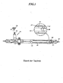
Im Allgemeinen ist eine Lenkvorrichtung zwischen dem Sitz eines Fahrers und den Rädern zur Bewegung der Räder durch einen Fahrer eingerichtet. Die Lenkvorrichtung umfasst eine Lenkspindel bzw. Lenkwelle, die sich auf einer unteren Seite des Lenkrades des Fahrersitzes befindet, ein Getriebe bzw. Getriebegehäuse, das mit der Lenkspindel verbunden ist, und einen Zahnstangenstab, der mit den Rädern verbunden ist, während er sich in einer linken und rechten Richtung erstreckt, um so die Räder direkt entsprechend einer Betätigung des Getriebes zu betätigen.In general, a steering device is installed between a driver's seat and the wheels for a driver to move the wheels. The steering device includes a steering shaft located on a lower side of the steering wheel of the driver's seat, a gear box connected to the steering shaft, and a rack bar connected to the wheels while in one extends left and right directions so as to operate the wheels directly in accordance with an operation of the transmission.
Wie in
Das Getriebegehäuse
Das Getriebegehäuse
Das Zahnstangengehäuse
Das Zahnstangengehäuse
Der Zahnstangenstab
In der Zwischenzeit ist die Zahnstangenbuchse
Die Zahnstangenbuchse
Das heißt, der Zahnstangenanschlag
Die Zahnstangenbuchse und die die Zahnstangenbuchse aufweisende Lenkvorrichtung vom Zahnstangen/Ritzel -Typ für ein Fahrzeug gemäß dem Stand der Technik weisen ein Problem darin auf, dass die Last in einer axialen Richtung und einer vertikalen Richtung des Zahnstangenstabes auf die Zahnstangenbuchse durch den Zahnstangenstab, die Zahnstangenbuchse und das Zahnstangengehäuse während des Lenkens des Lenkrades durch den Fahrer übertragen wird, so dass ein anormaler Verschleiß und Geräusche in der Zahnstangenbuchse erzeugt werden.The rack socket and the rack and pinion type steering device for a vehicle according to the prior art have a problem in that the load in an axial direction and a vertical direction of the rack rod is applied to the rack socket by the rack rod, the rack socket and the rack housing is transmitted during steering of the steering wheel by the driver, so that abnormal wear and noise are generated in the rack socket.
Darüber hinaus scheitert die Zahnstangenbuchse daran, die Last in einer axialen Richtung und einer vertikalen Richtung des Zahnstangenstabes gleichmäßig und stoßfrei abzustützen, so dass der Zahnstangenstab und die Ritzelwelle in Folge der Einwirkung, die von außen durch eine Fahrbahnoberfläche übertragen wird, beschädigt werden.In addition, the rack bushing fails to evenly and smoothly support the load in an axial direction and a vertical direction of the rack bar, so that the rack bar and the pinion shaft are damaged due to the action transmitted from the outside through a road surface.
Dementsprechend ist die vorliegende Erfindung geschaffen worden, um die oben erwähnten Probleme zu lösen, die im Stand der Technik auftreten.Accordingly, the present invention has been made to solve the above-mentioned problems encountered in the prior art.
Diese Aufgabe wird gelöst durch eine Zahnstangenbuchse mit den Merkmalen des Patentanspruchs 1 und eine Lenkvorrichtung vom Zahnstangen/Ritzel-Typ mit den Merkmalen des Patentanspruchs 10.This object is achieved by a rack and pinion bushing having the features of claim 1 and a steering device of the rack and pinion type having the features of claim 10.
Die vorliegende Erfindung stellt eine Zahnstangenbuchse und eine die Zahnstangenbuchse aufweisende Lenkvorrichtung vom Zahnstangen/Ritzel-Typ für ein Fahrzeug bereit, welche eine Last in einer axialen Richtung und einer vertikalen Richtung eines Zahnstangenstabes gleichmäßig und stoßfrei abstützen können, so dass es möglich ist, einen anormalen Verschleiß der Zahnstangenbuchse zu reduzieren, ein Klappergeräusch zu reduzieren, das von einer externen Kraft verursacht wird, die durch den Zahnstangenstab während der Bewegung des Zahnstangenstabes übertragen wird, und eine Beschädigung des Zahnstangenstabes und eines Ritzels durch die Verteilung der Last in Folge einer äußeren Einwirkung auf die Welle zu verhindern.The present invention provides a rack and pinion type steering device having the rack and pinion type for a vehicle, which can support a load in an axial direction and a vertical direction of a rack bar smoothly and smoothly, so that it is possible to fix an abnormal Reducing wear of the rack bushing, reducing rattling noise caused by an external force transmitted through the rack bar during the movement of the rack bar, and damage to the rack bar and a pinion due to the distribution of load due to an external action to prevent the wave.
In Übereinstimmung mit einem Aspekt der vorliegenden Erfindung wird eine Zahnstangenbuchse bereitgestellt, die Folgendes umfasst: einen Buchsenkörper, der wie ein hohles Rohr geformt ist, von dem eine äußere periphere Fläche mit einer inneren Seite eines Zahnstangengehäuses zusammengefügt ist und eine innere periphere Fläche mit einem Zahnstangenstab zusammengefügt ist, wobei der Buchsenkörper wenigstens einen abgestuften Abschnitt, durch den die äußere periphere Fläche des Buchsenkörpers mehrere Außendurchmesser aufweist, die ausgehend von einem Seitenende zu einem anderen Seitenende davon kleiner werden, so dass der Buchsenkörper von dem Zahnstangenstab und dem Zahnstangengehäuse abgestützt wird und die Steifigkeit aufrecht erhält, wenigstens einen ersten Schlitz, der durch Einschneiden dieses einen Seitenendes in einer axialen Richtung ausgebildet ist, und wenigstens einen zweiten Schlitz umfasst, der durch Einschneiden des anderen Seitenendes in der axialen Richtung ausgebildet ist und von dem ersten Schlitz beabstandet ist, wobei der wenigstens eine erste Schlitz und der wenigstens eine zweite Schlitz zueinander versetzt sind; und ein elastisches Element, das eine ringförmige Form aufweist und sich in engem Kontakt mit der äußeren peripheren Fläche des Buchsenkörpers befindet.In accordance with one aspect of the present invention, there is provided a rack bushing comprising: a bushing body shaped like a hollow tube having an outer peripheral surface mated with an inner side of a rack housing and an inner peripheral surface with a rack bar is joined together, wherein the socket body has at least one stepped portion through which the outer peripheral surface of the socket body has a plurality of outer diameters that are smaller starting from one side end to another side end thereof, so that the socket body is supported by the rack rod and the rack housing and the Maintaining rigidity, comprises at least a first slit formed by cutting this one side end in one axial direction and at least one second slit formed by cutting the other side end in the axial direction and spaced from the first slot, the at least one first slot and the at least one second slot being offset from one another; and an elastic one A member that is annular in shape and is in close contact with the outer peripheral surface of the socket body.
In Übereinstimmung mit einem weiteren Aspekt der vorliegenden Erfindung ist eine Lenkvorrichtung vom Zahnstangen/Ritzel-Typ für ein Fahrzeug bereitgestellt, die Folgendes umfasst: ein Zahnstangengehäuse, das mit einer Zahnstangenbuchse an einer inneren Seite des Zahnstangengehäuses zusammengefügt ist; und einen Zahnstangenstab, der von einer inneren peripheren Fläche der Zahnstangenbuchse abgestützt wird, um sich in dem Zahnstangengehäuse hin- und herzubewegen, wobei die Zahnstangenbuchse Folgendes umfasst: einen Buchsenkörper, der wie ein hohles Rohr geformt ist, von dem eine äußere periphere Fläche mit einer inneren Seite eines Zahnstangengehäuses zusammengefügt ist und eine innere periphere Fläche mit einem Zahnstangenstab zusammengefügt ist, wobei der Buchsenkörper wenigstens einen abgestuften Abschnitt, durch den die äußere periphere Fläche des Buchsenkörpers mehrere Außendurchmesser aufweist, die ausgehend von einem Seitenende zu dem anderen Seitenende davon kleiner werden, so dass der Buchsenkörper von dem Zahnstangenstab und dem Zahnstangengehäuse abgestützt wird und die Steifigkeit aufrecht erhält, wenigstens einen ersten Schlitz, der durch Einschneiden dieses einen Seitenendes in einer axialen Richtung ausgebildet ist, und wenigstens einen zweiten Schlitz umfasst, der durch Einschneiden des anderen Seitenendes in der axialen Richtung ausgebildet ist und von dem ersten Schlitz beabstandet ist, wobei der wenigstens eine erste Schlitz und der wenigstens eine zweite Schlitz zueinander versetzt sind; und ein elastisches Element, das eine ringförmige Form aufweist und sich in Kontakt mit der äußeren peripheren Fläche des Buchsenkörpers befindet.In accordance with another aspect of the present invention, there is provided a rack and pinion type steering apparatus for a vehicle, comprising: a rack housing mated with a rack socket on an inner side of the rack housing; and a rack bar supported by an inner peripheral surface of the rack sleeve to reciprocate in the rack housing, the rack sleeve comprising: a sleeve body shaped like a hollow tube, an outer peripheral surface of which is provided with a inner side of a rack housing is assembled and an inner peripheral surface is assembled with a rack bar, the socket body having at least one stepped portion through which the outer peripheral surface of the socket body has a plurality of outer diameters which become smaller from one side end to the other side end thereof, so that the socket body is supported by the rack rod and the rack housing and maintains rigidity, at least a first slot formed by cutting this one side end in an axial direction and at least a second slot formed through h cutting the other side end is formed in the axial direction and is spaced apart from the first slit, wherein the at least one first slit and the at least one second slit are offset from each other; and an elastic member having an annular shape and being in contact with the outer peripheral surface of the socket body.
Folglich gibt es eine Wirkung dahingehend, dass die Zahnstangenbuchse und die die Zahnstangenbuchse aufweisende Lenkvorrichtung vom Zahnstangen/Ritzel-Typ für ein Fahrzeug in Übereinstimmung mit der vorliegenden Erfindung die Last in einer axialen Richtung und einer vertikalen Richtung eines Zahnstangenstabes gleichmäßig und stoßfrei abstützen können, so dass es möglich ist, einen anormalen Verschleiß der Zahnstangenbuchse zu reduzieren, ein Klappergeräusch zu reduzieren, das durch eine externe Kraft verursacht wird, die durch den Zahnstangenstab während der Bewegung des Zahnstangenstabes übertragen wird, und eine Beschädigung des Zahnstangenstabes und des Ritzels durch die Verteilung der Last in Folge einer Einwirkung von außen auf die Welle zu verhindern.Consequently, there is an effect that the rack and pinion type steering device including the rack and pinion type steering device for a vehicle in accordance with the present invention can smoothly and smoothly support the load in an axial direction and a vertical direction of a rack bar, so that it is possible to reduce abnormal wear of the rack sleeve, reduce rattling noise caused by an external force transmitted through the rack bar during the movement of the rack bar, and damage to the rack bar and the pinion due to the distribution of the To prevent load as a result of an external action on the shaft.
Die oben genannten und weitere Aufgaben, Merkmale und Vorteile der vorliegenden Erfindung werden aus der nachfolgenden ausführlichen Beschreibung, die in Verbindung mit den beigefügten Zeichnungen vorgenommen wird, ersichtlicher, in denen:
-
1 eine teilweise im Querschnitt dargestellte Ansicht ist, die eine Lenkvorrichtung vom Zahnstangen/Ritzel-Typ für ein Fahrzeug gemäß dem Stand der Technik veranschaulicht; -
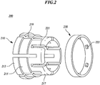
2 eine perspektivische Ansicht in aufgelösten Einzelteilen ist, die eine Zahnstangenbuchse in Übereinstimmung mit einem ersten Ausführungsbeispiel der vorliegenden Erfindung veranschaulicht; -
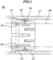
3 eine Querschnittsansicht ist, die eine Zahnstangenbuchse in Übereinstimmung mit einem ersten Ausführungsbeispiel der vorliegenden Erfindung veranschaulicht; -
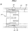
4 eine Querschnittsansicht ist, die eine Zahnstangenbuchse in Übereinstimmung mit einem zweiten Ausführungsbeispiel der vorliegenden Erfindung veranschaulicht; und -
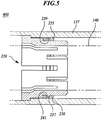
5 eine Querschnittsansicht ist, die eine Zahnstangenbuchse in Übereinstimmung mit einem dritten Ausführungsbeispiel der vorliegenden Erfindung veranschaulicht.
-
1 Fig. 13 is a partially cross-sectional view illustrating a rack and pinion type steering device for a vehicle according to the prior art; -
2 Figure 3 is an exploded perspective view illustrating a rack and pinion sleeve in accordance with a first embodiment of the present invention; -
3 Fig. 3 is a cross-sectional view illustrating a rack bushing in accordance with a first embodiment of the present invention; -
4th Fig. 3 is a cross-sectional view illustrating a rack bushing in accordance with a second embodiment of the present invention; and -
5 Figure 13 is a cross-sectional view illustrating a rack sleeve in accordance with a third embodiment of the present invention.
Im Folgenden werden bevorzugte Ausführungsbeispiele der vorliegenden Erfindung unter Bezugnahme auf die beigefügten Zeichnungen beschrieben werden. In der nachfolgenden Beschreibung werden die gleichen Elemente mit den gleichen Bezugszeichen bezeichnet werden, obwohl sie in verschiedenen Zeichnungen gezeigt sind. In der nachfolgenden Beschreibung kann eine ausführliche Erläuterung bekannter, damit in Beziehung stehender Funktionen und Konstitutionen weggelassen werden, um eine unnötige Verschleierung des Gegenstandes der vorliegenden Erfindung zu vermeiden.In the following, preferred embodiments of the present invention will be described with reference to the accompanying drawings. In the following description, the same elements will be denoted by the same reference numerals even though they are shown in different drawings. In the following description, detailed explanation of known related functions and constitutions may be omitted in order to avoid unnecessarily obscuring the subject matter of the present invention.
Außerdem kann einen Terminus eines ersten, eines zweiten, A, B, (a), (b) und dergleichen zum Beschreiben eines Konstruktionselements der vorliegenden Erfindung verwendet werden. Ein solcher Terminus dient lediglich zur Unterscheidung des entsprechenden Konstruktionselements von einem anderen Konstruktionselement, beschränkt aber nicht eine Beschaffenheit, eine Sequenz oder eine Reihenfolge des entsprechenden Konstruktionselements. Wenn beschrieben wird, dass ein Konstruktionselement mit einem anderen Konstruktionselement „gekoppelt“, „zusammengefügt“ oder „verbunden“ ist, dann kann das Konstruktionselement direkt mit einem anderen Konstruktionselement gekoppelt oder verbunden sein, aber es wird außerdem klar sein, dass ein anderes Konstruktionselement ferner zwischen jedem der Konstruktionselemente „gekoppelt“, „zusammengefügt“. oder „verbunden“ sein kann.In addition, a term of a first, a second, A, B, (a), (b), and the like can be used to describe a structural element of the present invention. Such a term only serves to distinguish the corresponding construction element from another construction element, but does not limit a nature, a sequence or an order of the corresponding construction element. If a construction element is described as being "coupled", "joined" or "connected" to another construction element, then the construction element may be directly coupled or connected to another construction element, but it will also be understood that another construction element is also between each of the construction elements "coupled", "joined together". or can be "connected".
Wie in den
Der abgestufte Abschnitt des Buchsenkörpers
Der Zahnstangenstab
Der Zahnstangenstab
Zu diesem Zeitpunkt wird der Zahnstangenstab
Der Buchsenkörper
Die Zahnstangenbuchse
Der Buchsenkörper
Der Abschnitt
Darüber hinaus weist der Buchsenkörper
Ferner sind in dem Buchsenkörper
Der Buchsenkörper
Darüber hinaus umfasst der Buchsenkörper
Der erste Schlitz
Das heißt, der erste Schlitz
Des Weiteren sind der erste Schlitz
In der Zwischenzeit ist der Buchsenkörper
Das elastische Element
Deshalb rutscht das elastische Element
Das elastische Element
Darüber hinaus umfasst, wie in
Deshalb ist es möglich, eine Fläche zu reduzieren, in der sich das elastische Element
Zusätzlich umfasst, wie in
Deshalb ist es möglich, die Fläche zu reduzieren, in der sich das elastische Element
Wie oben unter Bezugnahme auf
Folglich weist die vorliegende Erfindung, die die obige Struktur und Form aufweist, eine Wirkung dahingehend auf, dass sie die Last in der axialen Richtung und der vertikalen Richtung des Zahnstangenstabes gleichmäßig und stoßfrei abstützt, wodurch ein anormaler Verschleiß der Zahnstangenbuchse reduziert wird, das Klappergeräusch verringert wird, das durch die externe Kraft verursacht wird, die durch den Zahnstangenstab während der Bewegung des Zahnstangenstabes übertragen wird, und die Beschädigung des Zahnstangenstabes und der Ritzelwelle durch die Verteilung der Last bedingt durch eine Einwirkung von außen verhindert wird.Accordingly, the present invention having the above structure and shape has an effect of supporting the load in the axial direction and the vertical direction of the rack bar smoothly and smoothly, thereby reducing abnormal wear of the rack bushing, reducing rattling noise caused by the external force transmitted through the rack bar during the movement of the rack bar, and the damage to the rack bar and the pinion shaft due to the distribution of the load due to an external action is prevented.
Obwohl in der obigen Beschreibung beschrieben wird, dass jedes Konstruktionselement in dem Ausführungsbeispiel der vorliegenden Erfindung durch das Zusammenfügen miteinander betätigt wird, ist die vorliegende Beschreibung nicht notwendigerweise auf das Ausführungsbeispiel beschränkt. Das heißt, wenigstens ein Konstruktionselement kann selektiv für eine Betätigung innerhalb eines Bereichs der Aufgabe der vorliegenden Erfindung zusammengefügt werden.Although in the above description it is described that each structural member in the embodiment of the present invention is operated by being fitted together, the present description is not necessarily limited to the embodiment. That is, at least one structural element can be selectively assembled for operation within a range of the object of the present invention.
Darüber hinaus besitzen die Termini „umfassen“, „konstruieren“ oder „aufweisen“, die in der obigen Beschreibung verwendet wurden, eine Bedeutung, die das entsprechende Konstruktionselement einschließt, solange es keine spezifische gegenteilige Beschreibung gibt. Deshalb soll dies so interpretiert werden, dass es ferner ein weiteres Konstruktionselement einschließt, aber kein anderes Konstruktionselement ausschließt. Jeder Terminus, der einen technischen oder wissenschaftlichen Begriff einschließt, weist eine identische Bedeutung auf, die von den Fachleuten auf diesem Gebiet allgemein verstanden wird, wenn er nicht anders definiert ist. Die allgemeinen Termini, wie etwa ein Terminus, der in dem Wörterbuch definiert ist, sollte als die Bedeutung interpretiert werden, die er entsprechend einer Kontextbedeutung der damit in Beziehung stehenden Technologie aufweist, und sollte nicht als eine ideale oder übermäßig formelle Bedeutung interpretiert werden, solange sie nicht offensichtlich in der vorliegenden Erfindung definiert sind.In addition, the terms “comprising”, “constructing” or “having” used in the above description have a meaning that includes the corresponding construction element, unless there is a specific description to the contrary. Therefore, this should be interpreted in such a way that it also includes a further construction element, but does not exclude any other construction element. Each term that includes a technical or scientific term has an identical meaning that is commonly understood by those skilled in the art, unless otherwise defined. The general terms such as a term defined in the dictionary should be interpreted as the meaning it has according to a contextual meaning of the related technology, and should not be interpreted as an ideal or overly formal meaning so long they are not obviously defined in the present invention.
Obwohl ein exemplarisches Ausführungsbeispiel der vorliegenden Erfindung zu veranschaulichenden Zwecken beschrieben worden ist, wird es den Fachleuten auf dem Gebiet klar sein, dass verschiedene Modifikationen, Additionen und Substitutionen möglich sind, ohne dass von dem Schutzumfang und dem Gedanken der Erfindung, wie sie in den beigefügten Ansprüchen offenbart ist, abgewichen wird. Obgleich die vorliegende Erfindung unter Bezugnahme auf bestimmte exemplarische Ausführungsbeispiele davon gezeigt und beschrieben worden ist, wird es von den Fachleuten auf dem Gebiet verstanden werden, dass verschiedene Änderungen bezüglich Form und Einzelheiten darin durchgeführt werden können, ohne dass von dem Erfindungsgedanken und dem Schutzumfang der Erfindung, wie sie in den angehängten Ansprüchen definiert ist, abgewichen wird. Deshalb ist ein exemplarisches Ausführungsbeispiel der vorliegenden Erfindung nicht für beschränkende Zwecke beschrieben worden, so dass der Schutzumfang und der Erfindungsgedanke der Erfindung nicht durch das exemplarische Ausführungsbeispiel davon beschränkt werden dürfen. Folglich soll der Schutzumfang der Erfindung nicht durch die oben aufgeführten Ausführungsbeispiele beschränkt werden, sondern durch die Ansprüche und deren Äquivalente.Although an exemplary embodiment of the present invention has been described for illustrative purposes, it will be apparent to those skilled in the art that various modifications, additions, and substitutions are possible without departing from the scope and spirit of the invention as set forth in the accompanying drawings Claims is disclosed, is deviated. While the present invention has been shown and described with reference to certain exemplary embodiments thereof, it will be understood by those skilled in the art that various changes in form and details can be made therein without departing from the spirit and scope of the invention as defined in the appended claims. Therefore, an exemplary embodiment of the present invention has not been described for restrictive purposes, so that the scope and inventive concept of the invention may not be limited by the exemplary embodiment thereof. Consequently, the scope of the invention is not to be limited by the exemplary embodiments listed above, but by the claims and their equivalents.
Claims (17)
Applications Claiming Priority (2)
| Application Number | Priority Date | Filing Date | Title |
|---|---|---|---|
| KR10-2009-0028769 | 2009-04-03 | ||
| KR1020090028769A KR101277928B1 (en) | 2009-04-03 | 2009-04-03 | Rack Bush, and Rack and Pinion Type Steering Apparatus for Vehicle having The Same |
Publications (2)
| Publication Number | Publication Date |
|---|---|
| DE102010013552A1 DE102010013552A1 (en) | 2010-11-25 |
| DE102010013552B4 true DE102010013552B4 (en) | 2021-04-08 |
Family
ID=42825075
Family Applications (1)
| Application Number | Title | Priority Date | Filing Date |
|---|---|---|---|
| DE102010013552.6A Active DE102010013552B4 (en) | 2009-04-03 | 2010-03-31 | Rack and pinion bushing and steering device of the rack and pinion type having the rack and pinion bushing for a vehicle |
Country Status (4)
| Country | Link |
|---|---|
| US (1) | US8429991B2 (en) |
| KR (1) | KR101277928B1 (en) |
| CN (1) | CN101858418B (en) |
| DE (1) | DE102010013552B4 (en) |
Cited By (1)
| Publication number | Priority date | Publication date | Assignee | Title |
|---|---|---|---|---|
| DE102024103848A1 (en) * | 2024-02-12 | 2025-08-14 | Oiles Corporation | Push rod system with moment support device and motor vehicle |
Families Citing this family (29)
| Publication number | Priority date | Publication date | Assignee | Title |
|---|---|---|---|---|
| US9073423B2 (en) * | 2009-01-17 | 2015-07-07 | Boomerang Systems, Inc. | Steering and drive assembly |
| US9409267B2 (en) * | 2010-06-17 | 2016-08-09 | Bendix Spicer Foundation Brake Llc | Snap-in center seal bushing |
| KR101450317B1 (en) * | 2010-11-08 | 2014-10-23 | 주식회사 만도 | Preventing Device for Rattle Noise of Rack Bar |
| EP2703252B1 (en) * | 2011-04-25 | 2017-08-16 | NSK Ltd. | Rack-and-pinion steering gear unit |
| CN102424227A (en) * | 2011-08-29 | 2012-04-25 | 南通冷冻设备有限公司 | Low-temperature plastic rolling wheel frame |
| CN103029744B (en) * | 2011-10-05 | 2017-09-12 | 株式会社捷太格特 | Rack pinion formula transfer, its assemble method and bushing |
| BR112015005493B1 (en) * | 2012-09-30 | 2022-08-09 | Saint-Gobain Performance Plastics Corporation | STEERING FORK ASSEMBLY |
| US9272727B2 (en) * | 2012-10-24 | 2016-03-01 | Jtekt Corporation | Steering system |
| US8987612B2 (en) * | 2012-11-26 | 2015-03-24 | The Boeing Company | Bushings, apparatuses including bushings, and associated methods |
| JP6115301B2 (en) * | 2013-05-14 | 2017-04-19 | オイレス工業株式会社 | Synthetic plastic plain bearing |
| JP6150119B2 (en) * | 2013-07-22 | 2017-06-21 | 株式会社ジェイテクト | Rack bush |
| CN103836155A (en) * | 2013-12-27 | 2014-06-04 | 镇江恒宇传动机械有限责任公司 | Flexible guiding body with variable inner diameter and variable outer diameter |
| JP6034812B2 (en) * | 2014-01-23 | 2016-11-30 | 株式会社ショーワ | Bush bearing structure |
| US9873448B2 (en) * | 2014-03-31 | 2018-01-23 | Steering Solutions Ip Holding Corporation | End of travel stop |
| KR102181865B1 (en) * | 2014-05-08 | 2020-11-23 | 주식회사 만도 | Steering apparatus for vehicle |
| JP2017019414A (en) * | 2015-07-10 | 2017-01-26 | 株式会社ジェイテクト | Rack bush |
| JP6528969B2 (en) * | 2015-08-21 | 2019-06-12 | 株式会社ジェイテクト | Steering device |
| KR102342115B1 (en) * | 2015-10-08 | 2021-12-23 | 현대모비스 주식회사 | Rack bush of steering apparatus for vehicle |
| SG10201704652XA (en) * | 2016-06-07 | 2018-01-30 | Haydon Kerk Motion Solutions Inc | Lead screw nut device |
| KR102454512B1 (en) * | 2016-06-17 | 2022-10-14 | 현대모비스 주식회사 | Mounting bush |
| US10550889B2 (en) | 2016-08-01 | 2020-02-04 | Battelle Memorial Institute | Snap-in bushings and process for high-pressure and/or high temperature magic angle spinning nuclear magnetic resonance spectroscopy |
| DE102016114678A1 (en) * | 2016-08-08 | 2018-02-08 | Thyssenkrupp Ag | Rotary bearing arrangement for a steering column of a motor vehicle |
| JP2018177019A (en) * | 2017-04-14 | 2018-11-15 | 株式会社ジェイテクト | Steering device |
| CN108825657A (en) * | 2018-06-28 | 2018-11-16 | 安徽恒均粉末冶金科技股份有限公司 | Motor shaft sleeve and its manufacturing method |
| US10837677B2 (en) * | 2018-09-05 | 2020-11-17 | Ojjo, Inc. | Multi-piece truss legs and related couplers |
| DE102018124905A1 (en) | 2018-10-09 | 2020-04-09 | Thyssenkrupp Ag | Plain bearing for a coupling rod of a steer-by-wire steering gear |
| CN109501854A (en) * | 2018-12-23 | 2019-03-22 | 新乡艾迪威汽车科技有限公司 | A kind of rack support structure of automobile steering device |
| KR102173415B1 (en) * | 2019-06-04 | 2020-11-03 | 현대모비스 주식회사 | Rack bush of steering device for vehicle |
| KR102207576B1 (en) * | 2019-11-07 | 2021-01-26 | 현대모비스 주식회사 | Rack bush of steering device for vehicle |
Citations (5)
| Publication number | Priority date | Publication date | Assignee | Title |
|---|---|---|---|---|
| US5181581A (en) * | 1991-02-08 | 1993-01-26 | Trw Inc. | Rack bushing with integral seal |
| JP2004132511A (en) * | 2002-10-11 | 2004-04-30 | Oiles Ind Co Ltd | Bush bearing |
| JP2004183780A (en) * | 2002-12-03 | 2004-07-02 | Oiles Ind Co Ltd | Bush bearing |
| DE102007042931A1 (en) * | 2007-09-08 | 2008-03-27 | Daimler Ag | Bearing for e.g. gear rack in passenger car, has bearing bush, by which gear rack is slidably supported within steering gear case and comprising annular disc region provided with slots, which extend up to bushing region |
| EP1975430A1 (en) * | 2006-01-16 | 2008-10-01 | JTEKT Corporation | Bush bearing device, and rack and pinion steering device for automobile, using the same |
Family Cites Families (8)
| Publication number | Priority date | Publication date | Assignee | Title |
|---|---|---|---|---|
| US620664A (en) * | 1899-03-07 | Louis nissim | ||
| DE2320338A1 (en) * | 1973-04-21 | 1974-10-31 | Zahnradfabrik Friedrichshafen | PLASTIC BEARING BUSH |
| JP4657590B2 (en) * | 2002-08-28 | 2011-03-23 | オイレス工業株式会社 | Sliding bearing and bearing mechanism including the same |
| JP2004314853A (en) * | 2003-04-17 | 2004-11-11 | Showa Corp | Rack bush for vehicle steering system |
| US7401789B2 (en) * | 2005-06-07 | 2008-07-22 | Trw Automotive U.S. Llc | Rack bushing for rack and pinion steering assembly |
| US7665747B2 (en) * | 2006-10-13 | 2010-02-23 | Gm Global Technology Operations, Inc. | Steering gear assembly having rack bushing |
| CN201065934Y (en) * | 2007-07-12 | 2008-05-28 | 广州机械科学研究院 | Drum-shape sealing ring |
| CN201193708Y (en) * | 2008-05-15 | 2009-02-11 | 广州机械科学研究院 | Seal ring of Chinese character 'shan' shape |
-
2009
- 2009-04-03 KR KR1020090028769A patent/KR101277928B1/en active Active
-
2010
- 2010-03-31 DE DE102010013552.6A patent/DE102010013552B4/en active Active
- 2010-04-02 CN CN2010101627021A patent/CN101858418B/en active Active
- 2010-04-02 US US12/753,338 patent/US8429991B2/en active Active
Patent Citations (5)
| Publication number | Priority date | Publication date | Assignee | Title |
|---|---|---|---|---|
| US5181581A (en) * | 1991-02-08 | 1993-01-26 | Trw Inc. | Rack bushing with integral seal |
| JP2004132511A (en) * | 2002-10-11 | 2004-04-30 | Oiles Ind Co Ltd | Bush bearing |
| JP2004183780A (en) * | 2002-12-03 | 2004-07-02 | Oiles Ind Co Ltd | Bush bearing |
| EP1975430A1 (en) * | 2006-01-16 | 2008-10-01 | JTEKT Corporation | Bush bearing device, and rack and pinion steering device for automobile, using the same |
| DE102007042931A1 (en) * | 2007-09-08 | 2008-03-27 | Daimler Ag | Bearing for e.g. gear rack in passenger car, has bearing bush, by which gear rack is slidably supported within steering gear case and comprising annular disc region provided with slots, which extend up to bushing region |
Cited By (1)
| Publication number | Priority date | Publication date | Assignee | Title |
|---|---|---|---|---|
| DE102024103848A1 (en) * | 2024-02-12 | 2025-08-14 | Oiles Corporation | Push rod system with moment support device and motor vehicle |
Also Published As
| Publication number | Publication date |
|---|---|
| US8429991B2 (en) | 2013-04-30 |
| KR20100110441A (en) | 2010-10-13 |
| US20100251839A1 (en) | 2010-10-07 |
| DE102010013552A1 (en) | 2010-11-25 |
| CN101858418B (en) | 2013-08-21 |
| KR101277928B1 (en) | 2013-06-27 |
| CN101858418A (en) | 2010-10-13 |
Similar Documents
| Publication | Publication Date | Title |
|---|---|---|
| DE102010013552B4 (en) | Rack and pinion bushing and steering device of the rack and pinion type having the rack and pinion bushing for a vehicle | |
| DE102013003902B4 (en) | Power steering device and housing for an electric power steering device. | |
| DE102012012303B4 (en) | Rack and pinion support device for a vehicle steering device | |
| WO2014177338A1 (en) | Steering gear | |
| EP3960605A1 (en) | Electric bicycle drive unit attachment assembly | |
| DE102008001878A1 (en) | Helical bevel gear i.e. worm gear, for electrical power steering for motor vehicle, has bearing ring designed as pivot ring, which exhibits swiveling axis that runs orthogonal to radial effective direction of pre-tensioning force | |
| WO2009094972A1 (en) | Axial ball joint with impact damping mechanism | |
| DE102013013682A1 (en) | Rack and pinion type steering device | |
| EP3426541B1 (en) | Steering gear | |
| DE102019133406A1 (en) | Push rod guide assembly, steering actuator and method for manufacturing a push rod guide assembly | |
| DE102012010902B4 (en) | Elastic support module and rack bar support device comprising the same for a vehicle steering device | |
| DE102020130011A1 (en) | POLYMER BELT PULLEY FOR ELECTRIC POWER STEERING | |
| DE212018000132U1 (en) | steering device | |
| DE102015203624B4 (en) | Steering device | |
| DE202005007923U1 (en) | Steering gear e.g. for toothed rack steering in vehicles, has housing with rack along axle can be adjusted and auxiliary support is at axial end of housing with auxiliary support limits bend of rack | |
| DE102013005283A1 (en) | Intermediate shaft of a vehicle steering device | |
| DE102016121412A1 (en) | Fixed bearing and steering gear | |
| DE102016008416A1 (en) | POWER STEERING DEVICE FROM THE DENTAL SUPPORT TYPE | |
| DE102014224653A1 (en) | Ball Screw | |
| DE102010017922A1 (en) | transmission | |
| DE20214566U1 (en) | Electric motor linear drive, especially telescopic furniture drive for adjustable furniture parts, has at least one spindle nut with several nut parts assembled in e.g. two halves | |
| DE102015013648B4 (en) | Ball return with axially mountable mounting sleeve | |
| DE102016218589A1 (en) | Device for manual and / or electromotive adjustment or locking of a first vehicle part and a second vehicle part relative to each other | |
| EP2640623B1 (en) | Roller-mounted rack and pinion drive | |
| DE102022201929A1 (en) | RACK DRIVEN POWER STEERING DEVICE |
Legal Events
| Date | Code | Title | Description |
|---|---|---|---|
| OP8 | Request for examination as to paragraph 44 patent law | ||
| R016 | Response to examination communication | ||
| R016 | Response to examination communication | ||
| R016 | Response to examination communication | ||
| R016 | Response to examination communication | ||
| R018 | Grant decision by examination section/examining division | ||
| R020 | Patent grant now final | ||
| R081 | Change of applicant/patentee |
Owner name: HL MANDO CORPORATION, PYEONGTAEK-SI, KR Free format text: FORMER OWNER: MANDO CORPORATION, PYEONGTAEK-SI, GYEONGGI-DO, KR |