DE102009048237A1 - Electrochemical cell and method of making such a cell - Google Patents
Electrochemical cell and method of making such a cell Download PDFInfo
- Publication number
- DE102009048237A1 DE102009048237A1 DE102009048237A DE102009048237A DE102009048237A1 DE 102009048237 A1 DE102009048237 A1 DE 102009048237A1 DE 102009048237 A DE102009048237 A DE 102009048237A DE 102009048237 A DE102009048237 A DE 102009048237A DE 102009048237 A1 DE102009048237 A1 DE 102009048237A1
- Authority
- DE
- Germany
- Prior art keywords
- layer
- electrode layer
- electrode
- electrochemical cell
- boundary
- Prior art date
- Legal status (The legal status is an assumption and is not a legal conclusion. Google has not performed a legal analysis and makes no representation as to the accuracy of the status listed.)
- Withdrawn
Links
Images


Classifications
-
- H—ELECTRICITY
- H01—ELECTRIC ELEMENTS
- H01M—PROCESSES OR MEANS, e.g. BATTERIES, FOR THE DIRECT CONVERSION OF CHEMICAL ENERGY INTO ELECTRICAL ENERGY
- H01M4/00—Electrodes
- H01M4/02—Electrodes composed of, or comprising, active material
-
- H—ELECTRICITY
- H01—ELECTRIC ELEMENTS
- H01M—PROCESSES OR MEANS, e.g. BATTERIES, FOR THE DIRECT CONVERSION OF CHEMICAL ENERGY INTO ELECTRICAL ENERGY
- H01M10/00—Secondary cells; Manufacture thereof
- H01M10/02—Details
-
- H—ELECTRICITY
- H01—ELECTRIC ELEMENTS
- H01M—PROCESSES OR MEANS, e.g. BATTERIES, FOR THE DIRECT CONVERSION OF CHEMICAL ENERGY INTO ELECTRICAL ENERGY
- H01M10/00—Secondary cells; Manufacture thereof
- H01M10/04—Construction or manufacture in general
- H01M10/0413—Large-sized flat cells or batteries for motive or stationary systems with plate-like electrodes
-
- H—ELECTRICITY
- H01—ELECTRIC ELEMENTS
- H01M—PROCESSES OR MEANS, e.g. BATTERIES, FOR THE DIRECT CONVERSION OF CHEMICAL ENERGY INTO ELECTRICAL ENERGY
- H01M10/00—Secondary cells; Manufacture thereof
- H01M10/05—Accumulators with non-aqueous electrolyte
- H01M10/058—Construction or manufacture
- H01M10/0585—Construction or manufacture of accumulators having only flat construction elements, i.e. flat positive electrodes, flat negative electrodes and flat separators
-
- H—ELECTRICITY
- H01—ELECTRIC ELEMENTS
- H01M—PROCESSES OR MEANS, e.g. BATTERIES, FOR THE DIRECT CONVERSION OF CHEMICAL ENERGY INTO ELECTRICAL ENERGY
- H01M4/00—Electrodes
- H01M4/02—Electrodes composed of, or comprising, active material
- H01M4/13—Electrodes for accumulators with non-aqueous electrolyte, e.g. for lithium-accumulators; Processes of manufacture thereof
-
- H—ELECTRICITY
- H01—ELECTRIC ELEMENTS
- H01M—PROCESSES OR MEANS, e.g. BATTERIES, FOR THE DIRECT CONVERSION OF CHEMICAL ENERGY INTO ELECTRICAL ENERGY
- H01M50/00—Constructional details or processes of manufacture of the non-active parts of electrochemical cells other than fuel cells, e.g. hybrid cells
- H01M50/10—Primary casings, jackets or wrappings of a single cell or a single battery
- H01M50/102—Primary casings, jackets or wrappings of a single cell or a single battery characterised by their shape or physical structure
- H01M50/103—Primary casings, jackets or wrappings of a single cell or a single battery characterised by their shape or physical structure prismatic or rectangular
-
- H—ELECTRICITY
- H01—ELECTRIC ELEMENTS
- H01M—PROCESSES OR MEANS, e.g. BATTERIES, FOR THE DIRECT CONVERSION OF CHEMICAL ENERGY INTO ELECTRICAL ENERGY
- H01M10/00—Secondary cells; Manufacture thereof
- H01M10/05—Accumulators with non-aqueous electrolyte
- H01M10/052—Li-accumulators
- H01M10/0525—Rocking-chair batteries, i.e. batteries with lithium insertion or intercalation in both electrodes; Lithium-ion batteries
-
- H—ELECTRICITY
- H01—ELECTRIC ELEMENTS
- H01M—PROCESSES OR MEANS, e.g. BATTERIES, FOR THE DIRECT CONVERSION OF CHEMICAL ENERGY INTO ELECTRICAL ENERGY
- H01M10/00—Secondary cells; Manufacture thereof
- H01M10/42—Methods or arrangements for servicing or maintenance of secondary cells or secondary half-cells
- H01M2010/4292—Aspects relating to capacity ratio of electrodes/electrolyte or anode/cathode
-
- Y—GENERAL TAGGING OF NEW TECHNOLOGICAL DEVELOPMENTS; GENERAL TAGGING OF CROSS-SECTIONAL TECHNOLOGIES SPANNING OVER SEVERAL SECTIONS OF THE IPC; TECHNICAL SUBJECTS COVERED BY FORMER USPC CROSS-REFERENCE ART COLLECTIONS [XRACs] AND DIGESTS
- Y02—TECHNOLOGIES OR APPLICATIONS FOR MITIGATION OR ADAPTATION AGAINST CLIMATE CHANGE
- Y02E—REDUCTION OF GREENHOUSE GAS [GHG] EMISSIONS, RELATED TO ENERGY GENERATION, TRANSMISSION OR DISTRIBUTION
- Y02E60/00—Enabling technologies; Technologies with a potential or indirect contribution to GHG emissions mitigation
- Y02E60/10—Energy storage using batteries
-
- Y—GENERAL TAGGING OF NEW TECHNOLOGICAL DEVELOPMENTS; GENERAL TAGGING OF CROSS-SECTIONAL TECHNOLOGIES SPANNING OVER SEVERAL SECTIONS OF THE IPC; TECHNICAL SUBJECTS COVERED BY FORMER USPC CROSS-REFERENCE ART COLLECTIONS [XRACs] AND DIGESTS
- Y02—TECHNOLOGIES OR APPLICATIONS FOR MITIGATION OR ADAPTATION AGAINST CLIMATE CHANGE
- Y02P—CLIMATE CHANGE MITIGATION TECHNOLOGIES IN THE PRODUCTION OR PROCESSING OF GOODS
- Y02P70/00—Climate change mitigation technologies in the production process for final industrial or consumer products
- Y02P70/50—Manufacturing or production processes characterised by the final manufactured product
-
- Y—GENERAL TAGGING OF NEW TECHNOLOGICAL DEVELOPMENTS; GENERAL TAGGING OF CROSS-SECTIONAL TECHNOLOGIES SPANNING OVER SEVERAL SECTIONS OF THE IPC; TECHNICAL SUBJECTS COVERED BY FORMER USPC CROSS-REFERENCE ART COLLECTIONS [XRACs] AND DIGESTS
- Y10—TECHNICAL SUBJECTS COVERED BY FORMER USPC
- Y10T—TECHNICAL SUBJECTS COVERED BY FORMER US CLASSIFICATION
- Y10T29/00—Metal working
- Y10T29/49—Method of mechanical manufacture
- Y10T29/49002—Electrical device making
- Y10T29/49108—Electric battery cell making
Landscapes
- Chemical & Material Sciences (AREA)
- Chemical Kinetics & Catalysis (AREA)
- Electrochemistry (AREA)
- General Chemical & Material Sciences (AREA)
- Engineering & Computer Science (AREA)
- Manufacturing & Machinery (AREA)
- Materials Engineering (AREA)
- Battery Electrode And Active Subsutance (AREA)
- Secondary Cells (AREA)
- Cell Separators (AREA)
- Primary Cells (AREA)
Abstract
Elektrochemische Zelle 1, umfassend zumindest einen Elektrodenstapel 2, der innerhalb einer Umhüllung 4 der elektrochemischen Zelle angeordnet ist, wobei der Elektrodenstapel 2 zumindest eine erste Elektrodenschicht 5 und eine zweite Elektrodenschicht 6 aufweist, wobei zwischen der ersten Elektrodenschicht 5 und der zweiten Elektrodenschicht 6 eine Separatorschicht 7 angeordnet ist, wobei die erste Elektrodenschicht 5 eine geringere flächige Ausdehnung aufweist als die zweite Elektrodenschicht 6, dadurch gekennzeichnet, dass benachbart an der ersten Elektrodenschicht 5 eine insbesondere mechanisch stabilisierende Randschicht 8 angeordnet ist.Electrochemical cell 1, comprising at least one electrode stack 2, which is arranged within a casing 4 of the electrochemical cell, the electrode stack 2 having at least a first electrode layer 5 and a second electrode layer 6, with a separator layer between the first electrode layer 5 and the second electrode layer 6 7 is arranged, the first electrode layer 5 having a smaller two-dimensional extent than the second electrode layer 6, characterized in that an in particular mechanically stabilizing edge layer 8 is arranged adjacent to the first electrode layer 5.
Description
Die Erfindung betrifft eine elektrochemische Zelle, umfassend einen Elektrodenstapel mit insbesondere mehreren Schichten von aktivem Material. Weiter betrifft die Erfindung ein Verfahren zur Herstellung einer vorgenannten elektrochemischen Zelle. Ferner betrifft die Erfindung eine Batterie mit wenigstens einer vorgenannten elektrochemischen Zelle.The invention relates to an electrochemical cell comprising an electrode stack with, in particular, several layers of active material. Furthermore, the invention relates to a method for producing an aforementioned electrochemical cell. Furthermore, the invention relates to a battery with at least one aforementioned electrochemical cell.
Es sind Lithiumionenzellen bekannt, bei denen Anoden und Kathoden abwechselnd angeordnet sind, wobei zwischen den Anoden und den Kathoden jeweils ein Separator vorgesehen ist. Insbesondere bei Lithiumionenzellen weisen die Kathoden in der Regel eine kleinere flächige Ausdehnung auf als die Anoden. Dadurch ergibt sich, dass in Randbereichen der Kathoden ein Spalt entstehen kann, so dass die Anoden in diesem Bereich verbogen werden können, insbesondere bei externem Druckaufbringen auf die elektrochemische Zelle. An Stellen mit vermehrtem Verbiegen können die elektrochemischen Zellen Alterungserscheinungen aufweisen.Lithium ion cells are known in which anodes and cathodes are arranged alternately, wherein a separator is provided in each case between the anodes and the cathodes. In particular, in the case of lithium-ion cells, the cathodes generally have a smaller areal extent than the anodes. This results in that a gap may arise in edge regions of the cathodes, so that the anodes can be bent in this region, in particular in the case of external pressure application to the electrochemical cell. At sites of increased bending, the electrochemical cells may exhibit signs of aging.
Es ist Aufgabe der vorliegenden Erfindung, eine verbesserte elektrochemische Zelle bereitzustellen.It is an object of the present invention to provide an improved electrochemical cell.
Die der Erfindung zu Grunde liegende Aufgabe wird gelöst durch eine elektrochemische Zelle, umfassend zumindest einen Elektrodenstapel, der innerhalb einer Umhüllung der Elektrochemischen Zelle angeordnet ist, wobei der Elektrodenstapel zumindest eine Kathodenschicht und eine Anodenschicht aufweist, wobei zwischen der ersten Elektrodenschicht und der zweiten Elektrodenschicht eine Separatorschicht angeordnet ist, wobei die Kathodenschicht eine geringere flächige Ausdehnung aufweist als die Anodenschicht, dadurch gekennzeichnet, dass benachbart an der ersten Elektrodenschicht eine Randschicht angeordnet ist. Die Randschicht ist vorzugsweise mechanisch stabilisierend ausgestaltet.The object underlying the invention is achieved by an electrochemical cell, comprising at least one electrode stack, which is arranged within a sheath of the electrochemical cell, wherein the electrode stack has at least one cathode layer and one anode layer, wherein between the first electrode layer and the second electrode layer Separator layer is arranged, wherein the cathode layer has a smaller areal extent than the anode layer, characterized in that adjacent to the first electrode layer, an edge layer is arranged. The edge layer is preferably made mechanically stabilizing.
Im Sinne der Erfindung ist unter einem Elektrodenstapel eine Einrichtung zu verstehen, welche als Baugruppe einer galvanischen Zelle auch der Speicherung chemischer Energie und zur Abgabe elektrischer Energie dient. Dazu weist der Elektrodenstapel mehrere plattenförmige Elemente auf, wenigstens zwei Elektroden, nämlich insbesondere Anode und Kathode, und einen Separator, welcher den Elektrolyt wenigstens teilweise aufnimmt. Vorzugsweise sind wenigstens eine Anode, ein Separator und eine Kathode übereinander gelegt bzw. gestapelt, wobei der Separator wenigstens teilweise zwischen Anode und Kathode angeordnet ist. Diese Abfolge von Anode, Separator und Kathode kann sich innerhalb des Elektrodenstapels beliebig oft wiederholen. Vorzugsweise sind die plattenförmigen Elemente zu einem Elektrodenwickel aufgewickelt. Nachfolgend wird der Begriff „Elektrodenstapel” auch für Elektrodenwickel verwendet. Vor der Abgabe elektrischer Energie wird gespeicherte chemische Energie in elektrische Energie gewandelt. Während des Ladens wird die dem Elektrodenstapel bzw. der galvanischen Zelle zugeführte elektrische Energie in chemische Energie gewandelt und abgespeichert. Vorzugsweise weist der Elektrodenstapel mehrere Elektrodenpaare und Separatoren auf. Besonders bevorzugt sind einige Elektroden untereinander insbesondere miteinander elektrisch verbunden.For the purposes of the invention, an electrode stack is to be understood as a device which, as an assembly of a galvanic cell, also serves to store chemical energy and to deliver electrical energy. For this purpose, the electrode stack has a plurality of plate-shaped elements, at least two electrodes, namely in particular anode and cathode, and a separator which at least partially receives the electrolyte. Preferably, at least one anode, a separator and a cathode are stacked or stacked, wherein the separator is at least partially disposed between the anode and the cathode. This sequence of anode, separator and cathode can be repeated as often as desired within the electrode stack. Preferably, the plate-shaped elements are wound into an electrode winding. In the following, the term "electrode stack" will also be used for electrode winding. Before the release of electrical energy stored chemical energy is converted into electrical energy. During charging, the electrical energy supplied to the electrode stack or the galvanic cell is converted into chemical energy and stored. Preferably, the electrode stack has a plurality of electrode pairs and separators. Particularly preferably, some electrodes are electrically connected to each other in particular.
Unter Umhüllung ist im Rahmen der Erfindung eine zumindest teilweise Begrenzung zu verstehen, welche die Elektrodenstapel nach außen hin abgrenzt. Die Umhüllung ist vorzugsweise gas- und flüssigkeitsdicht, so dass ein Materialaustausch mit der Umgebung nicht stattfinden kann. Die Elektrodenstapel sind innerhalb der Umhüllung angeordnet. Wenigstens ein Stromableiter, insbesondere zwei Stromableiter erstrecken sich aus der Umhüllung hinaus und dienen zum Anschließen der Elektrodenstapel. Die nach außen sich erstreckenden Stromableiter stellen dabei vorzugsweise den Pluspolanschluss und den Minuspolanschluss der Elektrochemischen Zelle dar. Jedoch können sich auch mehrere Stromableiter aus der Umhüllung erstrecken, insbesondere vier Stromableiter. Wenn die elektrochemische Zelle dabei zwei Elektrodenstapel aufweist, die miteinander in Reihe geschaltet sind, so sind zwei Elektroden unterschiedlicher Elektrodenstapel miteinander verbunden.Under the scope of the invention, an at least partial limitation is to be understood, which delimits the electrode stack to the outside. The envelope is preferably gas and liquid tight, so that a material exchange with the environment can not take place. The electrode stacks are disposed within the enclosure. At least one current conductor, in particular two current conductors extend out of the enclosure and serve to connect the electrode stacks. The outwardly extending current conductors preferably represent the positive pole connection and the negative pole connection of the electrochemical cell. However, it is also possible for a plurality of current conductors to extend out of the enclosure, in particular four current arresters. If the electrochemical cell has two electrode stacks which are connected in series with one another, two electrodes of different electrode stacks are connected to one another.
Ein Stromableiter ist dabei ein Element, welches aus einem stromleitenden Material hergestellt ist. Es dient zur Leitung von Strom zwischen zwei geometrisch von einander getrennten Punkten. Im vorliegenden Fall ist ein Stromableiter mit einem Elektrodenstapel verbunden. Insbesondere ist der Stromableiter dabei mit allen gleichartigen Elektroden eines Elektrodenstapels verbunden, d. h. entweder mit den Kathoden oder mit den Anoden. Es ist selbstverständlich, dass ein Stromableiter nicht mit den Kathoden und Anoden eines Elektrodenstapels gleichzeitig verbunden ist, da dies zu einem Kurzschluss führen würde. Jedoch kann ein Stromableiter mit unterschiedlichen Elektroden von unterschiedlichen Elektrodenstapeln verbunden sein, so z. B. bei einer Reihenschaltung der beiden Elektrodenstapel. Wenigstens ein Stromableiter erstreckt sich aus der Umhüllung und kann dabei zum Anschließen der Elektrochemischen Zelle nach außen dienen. Der Stromableiter kann mit einer oder mehreren Elektroden einstückig ausgebildet sein. Eine Abgrenzung zwischen Stromableiter und Elektrode kann darin gesehen werden, dass der Stromableiter insbesondere nicht mit aktivem Elektrodenmaterial beschichtet ist.A current collector is an element which is made of an electrically conductive material. It is used to conduct electricity between two geometrically separated points. In the present case, a current collector is connected to an electrode stack. In particular, the current conductor is connected to all similar electrodes of an electrode stack, d. H. either with the cathodes or with the anodes. It goes without saying that a current collector is not connected to the cathodes and anodes of an electrode stack at the same time, since this would lead to a short circuit. However, a current collector may be connected to different electrodes of different electrode stacks, such. B. in a series connection of the two electrode stack. At least one current collector extends from the enclosure and may serve to connect the electrochemical cell to the outside. The current collector may be integrally formed with one or more electrodes. A distinction between current collector and electrode can be seen in that the current conductor is not coated in particular with active electrode material.
Durch das Vorsehen der Randschicht an der ersten Elektrodenschicht kann die Kathodenschicht mechanisch vergrößert werden. Durch die Vergrößerung ergibt sich bei gleichbleibendem Druck eine verringerte Flächenpressung auf die Elektrodenschichten insbesondere auf die Kathodenschicht. Dabei ist die Kathodenschicht und die Randschicht vorzugsweise in einer gemeinsamen Ebene angeordnet. Die Separatorschicht, welche in Anlage zur ersten Elektrodenschicht ist und die Kathodenschicht in einem Randbereich der ersten Elektrodenschicht insbesondere überlappt, kann dabei von der Randschicht abgestützt werden. Mittelbar wird dadurch insbesondere auch die Anodenschicht, welche auf der der ersten Elektrodenschicht abgewandten Seite der Separatorschicht angeordnet ist, durch die Randschicht abgestützt. Hierdurch ergibt sich insbesondere eine Verringerung von Abbiegungen, die sich im Bereich der Überlappung der Separatorschicht und insbesondere auch der zweiten Elektrodenschicht in Randbereichen ergeben kann. Diese Abbiegungen können ansonsten insbesondere dann auftreten, wenn auf die elektrochemische Zelle von extern mit Kraft, insbesondere Druck, beaufschlagt wird. Dies kann insbesondere auch bei der Fertigung der Elektrochemischen Zelle der Fall sein. By providing the edge layer on the first electrode layer, the cathode layer can be mechanically enlarged. The enlargement results in a reduced surface pressure on the electrode layers, in particular on the cathode layer, while the pressure remains constant. In this case, the cathode layer and the edge layer are preferably arranged in a common plane. The separator layer, which is in contact with the first electrode layer and in particular overlaps the cathode layer in an edge region of the first electrode layer, can thereby be supported by the edge layer. In this way, the anode layer, which is arranged on the side of the separator layer facing away from the first electrode layer, is indirectly supported by the edge layer. This results in particular in a reduction of bends, which may result in the region of the overlap of the separator layer and in particular also of the second electrode layer in edge regions. Otherwise, these bends can occur in particular when the electrochemical cell is subjected to external force, in particular pressure. This may in particular also be the case in the production of the electrochemical cell.
Vorzugsweise ist die Randschicht zumindest an einer Seite der ersten Elektrodenschicht angeordnet. Insbesondere ist die Randschicht an einer Seite der ersten Elektrodenschicht angeordnet, von der ein Stromableiter an die Kathodenschicht angeschlossen ist. Der Stromableiter ist dabei vorzugsweise nicht von aktiven Elektrodenmaterial beschichtet. Insofern kann der Stromableiter eine Querschnittsdicke aufweisen, die geringer ist als die Querschnittsdicke der ersten Elektrodenschicht. Dadurch, dass im Bereich des Stromableiters die Randschicht angebracht ist, kann somit die Querschnittsdicke des Stromableiters um eine gewisse Querschnittsdicke der Randschicht insbesondere auf eine Querschnittsdicke aufsummiert werden, die der Querschnittsdicke der Kathodenschicht im Bereich der Schnittstelle zwischen Stromableiter und erster Elektrodenschicht entspricht.The edge layer is preferably arranged at least on one side of the first electrode layer. In particular, the boundary layer is arranged on one side of the first electrode layer, from which a current conductor is connected to the cathode layer. The current conductor is preferably not coated by active electrode material. In this respect, the current conductor may have a cross-sectional thickness which is smaller than the cross-sectional thickness of the first electrode layer. Because the edge layer is applied in the region of the current conductor, the cross-sectional thickness of the current conductor can thus be summed up by a certain cross-sectional thickness of the edge layer, in particular to a cross-sectional thickness which corresponds to the cross-sectional thickness of the cathode layer in the region of the interface between the current conductor and the first electrode layer.
Vorzugsweise ist die Randschicht zumindest an zwei jeweils gegenüberliegenden Seiten der ersten Elektrodenschicht angeordnet. Grundsätzlich kann nämlich die Randschicht aufgespaltet sein in mehrere insbesondere nicht miteinander verbundene Abschnitte der Randschicht. Dabei kann insbesondere sichergestellt werden, dass wenn die Kathodenschicht zentral zur zweiten Elektrodenschicht ausgerichtet ist, dass an beiden axialen Überständen der zweiten Elektrodenschicht diese Mittels der Randschicht, abgestützt werden kann.The edge layer is preferably arranged on at least two mutually opposite sides of the first electrode layer. In principle, namely, the edge layer can be split into several, in particular not interconnected, portions of the edge layer. In this case, it can be ensured, in particular, that when the cathode layer is aligned centrally with respect to the second electrode layer, that means of the edge layer can be supported on both axial projections of the second electrode layer.
Vorzugsweise ist die Randschicht umlaufend um die Kathodenschicht angeordnet. Dadurch kann ein umlaufender Bereich um die Kathodenschicht verstärkt werden. Insbesondere wird die Anodenschicht dadurch in einem umlaufenden Bereich von der Randschicht unterstützt. Die Randschicht kann einen insbesondere stützenden Rahmen um die Kathodenschicht bilden.Preferably, the edge layer is arranged circumferentially around the cathode layer. As a result, a circumferential area around the cathode layer can be reinforced. In particular, the anode layer is thereby supported in a peripheral region of the edge layer. The edge layer may form a particular supporting frame around the cathode layer.
Vorzugsweise bildet die Elektrodenschicht gemeinsam mit der Randschicht eine Verbundschicht. Die Verbundschicht hat dabei vorzugsweise die mechanischen Eigenschaften, die eine durchgehende Kathodenschicht hätte. Hierdurch können sämtliche Nachteile ausgeglichen werden, die sich durch die kleinere flächige Ausdehnung der ersten Elektrodenschicht ergeben können.The electrode layer preferably forms a composite layer together with the edge layer. The composite layer preferably has the mechanical properties that would have a continuous cathode layer. As a result, all the disadvantages can be compensated, which can result from the smaller areal extent of the first electrode layer.
Vorzugsweise entspricht eine Länge der Verbundschicht einer Länge der zweiten Elektrodenschicht. Vorzugsweise entspricht eine Breite der Verbundschicht einer Breite der zweiten Elektrodenschicht.Preferably, a length of the composite layer corresponds to a length of the second electrode layer. Preferably, a width of the composite layer corresponds to a width of the second electrode layer.
Vorzugsweise entspricht ein Umriss der Verbundschicht einem Umriss der zweiten Elektrodenschicht. Unter „entsprechen” ist dabei ein weitauszulegender Größenbegriff gemeint. Darunter sind insbesondere fertigungstechnisch bedingte Toleranzen zu verstehen. Ferner können dabei durchaus Abweichungen im einstelligen Prozentbereich zwischen den beiden Längenangaben liegen. Vorzugsweise sind die Abweichungen aber geringer, insbesondere kleiner als 5%, bezogen auf den geometrischen Flächeninhalt.An outline of the composite layer preferably corresponds to an outline of the second electrode layer. By "to conform" is meant a broader concept of size. This includes, in particular, production-related tolerances. Furthermore, deviations in the single-digit percentage range between the two length specifications may well be present. Preferably, however, the deviations are smaller, in particular less than 5%, based on the geometric surface area.
Vorzugsweise weist die Randschicht eine Querschnittsdicke auf, die im Wesentlichen einer Querschnittsdicke der ersten Elektrodenschicht entspricht. Dabei weist vorzugsweise die Randschicht eine Härte auf, die etwa der Härte der ersten Elektrodenschicht entspricht. Bei insbesondere ähnlichen mechanischen Eigenschaften, insbesondere ähnlichen elastischen und/oder plastischen Eigenschaften, kann die Randschicht eine vergrößerte Kathodenschicht simulieren. Insbesondere kann die erste Schicht eine Kathodenschicht sein und die zweite Schicht eine Anodenschicht sein.Preferably, the edge layer has a cross-sectional thickness which substantially corresponds to a cross-sectional thickness of the first electrode layer. In this case, preferably, the edge layer has a hardness which corresponds approximately to the hardness of the first electrode layer. In particular similar mechanical properties, in particular similar elastic and / or plastic properties, the edge layer can simulate an enlarged cathode layer. In particular, the first layer may be a cathode layer and the second layer may be an anode layer.
Ferner wird die Erfindung gelöst durch ein Verfahren zum Herstellen einer gattungsgemäßen Elektrochemischen Zelle, wobei zumindest an einer Seite der Elektrodenschicht eine Randschicht angebracht wird. Die Randschicht und die erste Elektrodenschicht können in einer gemeinsamen Ebene angeordnet werden. Die Randschicht kann zumindest an einer Seite der ersten Elektrodenschicht angeordnet werden, insbesondere an einer Seite der ersten Elektrodenschicht, von der ein Stromableiter an die ersten Elektrodenschicht angeschlossen ist. Vorzugsweise kann die Randschicht zumindest an zwei jeweils gegenüberliegenden Seiten der ersten Elektrodenschicht angeordnet werden. Weiter bevorzugt kann die Randschicht umlaufend um die ersten Elektrodenschicht angeordnet werden. Bevorzugt wird gemeinsam aus der ersten Elektrodenschicht mit der Randschicht eine Verbundschicht gebildet. Es wird auf die genannten Vorteile verwiesen.Furthermore, the invention is achieved by a method for producing a generic electrochemical cell, wherein at least on one side of the electrode layer, an edge layer is attached. The edge layer and the first electrode layer can be arranged in a common plane. The edge layer can be arranged at least on one side of the first electrode layer, in particular on one side of the first electrode layer, of which a current conductor is connected to the first electrode layer. Preferably, the edge layer at least on two opposite sides of the first Electrode layer can be arranged. More preferably, the edge layer can be arranged circumferentially around the first electrode layer. Preferably, a composite layer is formed together from the first electrode layer with the edge layer. Reference is made to the advantages mentioned.
Weitere Vorteile, Merkmale und Anwendungsmöglichkeiten der vorliegenden Erfindung ergeben sich aus der nachfolgenden Beschreibung in Zusammenhang mit den Figuren.Further advantages, features and applications of the present invention will become apparent from the following description taken in conjunction with the figures.
Es zeigt:It shows:
b) eine Kathode der Elektrochemischen Zelle gemäß
b) a cathode of the electrochemical cell according to
b) eine alternative Kathode gemäß
c) eine Anode der Elektrochemischen Zelle nach
b) an alternative cathode according to
c) an anode of the electrochemical cell according to
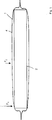
In
Die Randschicht
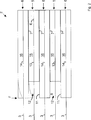
In
In
BezugszeichenlisteLIST OF REFERENCE NUMBERS
- 11
- Elektrochemische ZelleElectrochemical cell
- 22
- Elektrodenstapelelectrode stack
- 33
- StomableiterStomableiter
- 44
- Umhüllungwrapping
- 55
- Kathodenschichtcathode layer
- 66
- Anodenschichtanode layer
- 77
- Separatorschichtseparator
- 88th
- Randschichtboundary layer
- 99
- Seitepage
- 1010
- Verbundschichtcomposite layer
- 1111
- Randbereichborder area
- 1212
- Spaltgap
- 1313
- Kathodecathode
- 1414
- Anodeanode
- 1515
- aktives Kathodenmaterialactive cathode material
- 1616
- aktives Anodenmaterialactive anode material
- Ee
- Ebenelevel
- BB
- Breitewidth
- LL
- Längelength
- FF
- Kraftforce
Claims (18)
Priority Applications (8)
| Application Number | Priority Date | Filing Date | Title |
|---|---|---|---|
| DE102009048237A DE102009048237A1 (en) | 2009-10-05 | 2009-10-05 | Electrochemical cell and method of making such a cell |
| PCT/EP2010/005604 WO2011042111A1 (en) | 2009-10-05 | 2010-09-13 | Electrochemical cell and method for producing such a cell |
| KR1020127011575A KR20120091184A (en) | 2009-10-05 | 2010-09-13 | Electrochemical cell and method for producing such a cell |
| JP2012532475A JP2013506967A (en) | 2009-10-05 | 2010-09-13 | Electrochemical battery and method for producing such a battery |
| CN2010800443777A CN102687312A (en) | 2009-10-05 | 2010-09-13 | Electrochemical cell and method for producing such a cell |
| US13/500,388 US20120282517A1 (en) | 2009-10-05 | 2010-09-13 | Electrochemical cell and method for producing such a cell |
| BR112012007806A BR112012007806A2 (en) | 2009-10-05 | 2010-09-13 | electrochemical cell, battery and method to produce an electrochemical cell |
| EP10754695A EP2486614A1 (en) | 2009-10-05 | 2010-09-13 | Electrochemical cell and method for producing such a cell |
Applications Claiming Priority (1)
| Application Number | Priority Date | Filing Date | Title |
|---|---|---|---|
| DE102009048237A DE102009048237A1 (en) | 2009-10-05 | 2009-10-05 | Electrochemical cell and method of making such a cell |
Publications (1)
| Publication Number | Publication Date |
|---|---|
| DE102009048237A1 true DE102009048237A1 (en) | 2011-04-21 |
Family
ID=43086181
Family Applications (1)
| Application Number | Title | Priority Date | Filing Date |
|---|---|---|---|
| DE102009048237A Withdrawn DE102009048237A1 (en) | 2009-10-05 | 2009-10-05 | Electrochemical cell and method of making such a cell |
Country Status (8)
| Country | Link |
|---|---|
| US (1) | US20120282517A1 (en) |
| EP (1) | EP2486614A1 (en) |
| JP (1) | JP2013506967A (en) |
| KR (1) | KR20120091184A (en) |
| CN (1) | CN102687312A (en) |
| BR (1) | BR112012007806A2 (en) |
| DE (1) | DE102009048237A1 (en) |
| WO (1) | WO2011042111A1 (en) |
Cited By (2)
| Publication number | Priority date | Publication date | Assignee | Title |
|---|---|---|---|---|
| WO2020120100A1 (en) * | 2018-12-10 | 2020-06-18 | Robert Bosch Gmbh | Electrode stack for a galvanic cell |
| DE102021125288A1 (en) | 2021-09-29 | 2023-03-30 | Volkswagen Aktiengesellschaft | Battery cell and method for its manufacture |
Families Citing this family (1)
| Publication number | Priority date | Publication date | Assignee | Title |
|---|---|---|---|---|
| FR2997234B1 (en) * | 2012-10-22 | 2016-05-06 | Renault Sa | ELECTROCHEMICAL CELL FOR STORAGE OF ELECTRICITY. |
Family Cites Families (8)
| Publication number | Priority date | Publication date | Assignee | Title |
|---|---|---|---|---|
| US6946218B2 (en) * | 2002-09-06 | 2005-09-20 | Enerdel, Inc. | Battery cell having edge support and method of making the same |
| US7981548B2 (en) * | 2005-01-28 | 2011-07-19 | Nec Energy Devices, Ltd. | Multilayer secondary battery and method of making same |
| JP4932263B2 (en) * | 2005-01-28 | 2012-05-16 | Necエナジーデバイス株式会社 | Multilayer secondary battery and manufacturing method thereof |
| DE102005042916A1 (en) * | 2005-09-08 | 2007-03-22 | Degussa Ag | Stack of alternately stacked and fixed separators and electrodes for Li accumulators |
| JP5099407B2 (en) * | 2006-11-30 | 2012-12-19 | 住友電気工業株式会社 | battery |
| JP5526481B2 (en) * | 2007-06-06 | 2014-06-18 | 日産自動車株式会社 | Secondary battery and manufacturing method thereof |
| JP2009188037A (en) * | 2008-02-04 | 2009-08-20 | Fuji Heavy Ind Ltd | Electric storage device |
| JP5515267B2 (en) * | 2008-10-07 | 2014-06-11 | 日産自動車株式会社 | Nonaqueous electrolyte secondary battery |
-
2009
- 2009-10-05 DE DE102009048237A patent/DE102009048237A1/en not_active Withdrawn
-
2010
- 2010-09-13 EP EP10754695A patent/EP2486614A1/en not_active Withdrawn
- 2010-09-13 WO PCT/EP2010/005604 patent/WO2011042111A1/en active Application Filing
- 2010-09-13 CN CN2010800443777A patent/CN102687312A/en active Pending
- 2010-09-13 BR BR112012007806A patent/BR112012007806A2/en not_active IP Right Cessation
- 2010-09-13 KR KR1020127011575A patent/KR20120091184A/en not_active Application Discontinuation
- 2010-09-13 US US13/500,388 patent/US20120282517A1/en not_active Abandoned
- 2010-09-13 JP JP2012532475A patent/JP2013506967A/en active Pending
Cited By (2)
| Publication number | Priority date | Publication date | Assignee | Title |
|---|---|---|---|---|
| WO2020120100A1 (en) * | 2018-12-10 | 2020-06-18 | Robert Bosch Gmbh | Electrode stack for a galvanic cell |
| DE102021125288A1 (en) | 2021-09-29 | 2023-03-30 | Volkswagen Aktiengesellschaft | Battery cell and method for its manufacture |
Also Published As
| Publication number | Publication date |
|---|---|
| JP2013506967A (en) | 2013-02-28 |
| CN102687312A (en) | 2012-09-19 |
| WO2011042111A1 (en) | 2011-04-14 |
| KR20120091184A (en) | 2012-08-17 |
| BR112012007806A2 (en) | 2016-08-30 |
| US20120282517A1 (en) | 2012-11-08 |
| EP2486614A1 (en) | 2012-08-15 |
Similar Documents
| Publication | Publication Date | Title |
|---|---|---|
| DE112011100279T5 (en) | Battery cell module for a modular battery with a nested separating element | |
| EP2795694B1 (en) | Electrical energy storage module and method for producing an electrical energy storage module | |
| EP2795695B1 (en) | Electrical energy storage cell and method for producing an electrical energy storage cell | |
| DE112018002974T5 (en) | ENERGY STORAGE DEVICE | |
| DE112017001336T5 (en) | LEAD ACID BATTERY | |
| DE102009048237A1 (en) | Electrochemical cell and method of making such a cell | |
| EP2789030B1 (en) | Spacer for prismatic battery cell, prismatic battery comprising said spacer and method for producing a prismatic battery | |
| DE102018201489A1 (en) | battery cell | |
| WO2020001861A1 (en) | Battery cell that comprises an integrated heating element | |
| WO2013017208A1 (en) | Battery having a plurality of battery cells, and method for the production thereof | |
| DE102015226296A1 (en) | Accumulator cell and method for producing and operating an accumulator cell | |
| EP2399308B1 (en) | Galvanic cell | |
| DE102017112529B4 (en) | Single cell of a fuel cell | |
| EP3284119A1 (en) | Battery having a prismatic metal housing | |
| DE102013111108B4 (en) | Grid arrangement for a plate-shaped battery electrode of an electrochemical accumulator and accumulator | |
| DE102013202244A1 (en) | A cell connector for electrically contacting a plurality of battery cell terminals, a method of manufacturing such a cell connector, and a battery module having at least one such cell connector | |
| DE102020120578A1 (en) | Method of manufacturing an energy storage cell | |
| DE102016212782A1 (en) | Battery cell and battery | |
| DE102016220975A1 (en) | Current collector for an energy storage cell for storing electrical energy | |
| DE19838122B4 (en) | Partition wall or partition walls for cells in accumulators in pile or stacked construction and cell in pile or stacked construction | |
| DE102022103339A1 (en) | Battery and method of making a battery | |
| DE102018132716A1 (en) | Energy storage cell with cell stack and hard case housing and method for producing the same | |
| DE102020210448A1 (en) | Dimensionally stable battery cell housing and battery module made from at least two such battery cell housings | |
| DE102019211927A1 (en) | Battery module and method for manufacturing a battery module | |
| DE102019134634A1 (en) | Current collector device with low electrical resistance and lithium-ion battery with such a device |
Legal Events
| Date | Code | Title | Description |
|---|---|---|---|
| R082 | Change of representative | ||
| R119 | Application deemed withdrawn, or ip right lapsed, due to non-payment of renewal fee |