DE102008009827B4 - Safety mechanism for weapons - Google Patents
Safety mechanism for weapons Download PDFInfo
- Publication number
- DE102008009827B4 DE102008009827B4 DE102008009827.2A DE102008009827A DE102008009827B4 DE 102008009827 B4 DE102008009827 B4 DE 102008009827B4 DE 102008009827 A DE102008009827 A DE 102008009827A DE 102008009827 B4 DE102008009827 B4 DE 102008009827B4
- Authority
- DE
- Germany
- Prior art keywords
- catch
- firing
- securing
- linkage
- release position
- Prior art date
- Legal status (The legal status is an assumption and is not a legal conclusion. Google has not performed a legal analysis and makes no representation as to the accuracy of the status listed.)
- Expired - Fee Related
Links
Images
Classifications
-
- F—MECHANICAL ENGINEERING; LIGHTING; HEATING; WEAPONS; BLASTING
- F41—WEAPONS
- F41A—FUNCTIONAL FEATURES OR DETAILS COMMON TO BOTH SMALLARMS AND ORDNANCE, e.g. CANNONS; MOUNTINGS FOR SMALLARMS OR ORDNANCE
- F41A17/00—Safety arrangements, e.g. safeties
- F41A17/56—Sear safeties, i.e. means for rendering ineffective an intermediate lever transmitting trigger movement to firing pin, hammer, bolt or sear
Landscapes
- Engineering & Computer Science (AREA)
- General Engineering & Computer Science (AREA)
- Aiming, Guidance, Guns With A Light Source, Armor, Camouflage, And Targets (AREA)
- Toys (AREA)
- Portable Nailing Machines And Staplers (AREA)
- Lock And Its Accessories (AREA)
- Financial Or Insurance-Related Operations Such As Payment And Settlement (AREA)
- Mechanical Control Devices (AREA)
- Switches With Compound Operations (AREA)
Abstract
Sicherungsmechanik für vollautomatische Waffen, insbesondere Maschinenwaffen/-Gewehre, mit
– wenigstens einem zwischen einer Verschlussfangstellung und einer Freigabestellung verstellbaren Verschlussfanghebel (2; 23), und
– einer mit dem Verschlussfanghebel (2; 23) funktional verbundenen Abfeuereinheit (4; 26), die bei ihrer Betätigung den Verschlussfanghebel (2; 23) zur Schussabgabe in dessen Freigabestellung verbringt,
dadurch gekennzeichnet, dass
die Sicherungsmechanik weiter umfasst
– ein Sicherungs- und ein Abfeuergestänge (6, 7; 28, 29), wobei
– das Abfeuergestänge (7; 29) zwischen einer Ruhestellung und einer Auslösestellung, in der es die Abfeuereinheit (4, 26) zur Schussabgabe betätigt, verstellbar ist,
– das Sicherungsgestänge (6; 28) einen Sicherungsschieber (30) umfasst, und gemeinsam mit diesem zwischen einer Sicherungsstellung und einer Freigabestellung, in welcher das Abfeuergestänge (29) in seine Auslösestellung verbringbar ist, verstellbar ist, und
– ein Federelement, das das Sicherungsgestänge (6; 28) und den Sicherungsschieber (30) in deren Sicherungsstellung vorspannt, wobei der Sicherungsschieber (30) eine Verriegelungsklinke (31) derart beaufschlagt, dass der Verschlussfanghebel (23) an einer Drehbewegung nicht gehindert ist, in seine Verschlussfangstellung gelangt und den Verschluss fängt, unabhängig davon, ob ein zur Bedienung der Waffe zugehöriger Aktuator/Aktor im Griffstück ausfällt.Securing mechanism for fully automatic weapons, in particular machine guns / weapons, with
- At least one adjustable between a closing position and a release position locking catch lever (2, 23), and
A firing unit (4; 26) operatively connected to the shutter catch lever (2; 23) which, when actuated, spends the shutter catch lever (2; 23) for firing in its release position;
characterized in that
the safety mechanism further comprises
- A fuse and a firing linkage (6, 7, 28, 29), wherein
- the firing linkage (7; 29) is adjustable between a rest position and a release position in which it actuates the firing unit (4, 26),
- The fuse linkage (6, 28) comprises a safety slide (30), and together with this between a securing position and a release position in which the Abfeuergestänge (29) can be brought into its release position, is adjustable, and
A spring element which biases the securing linkage (6, 28) and the securing slide (30) into their securing position, the securing slide (30) acting on a locking pawl (31) in such a way that the slide catching lever (23) is not prevented from rotating; gets into its closed position and catch captures, regardless of whether a belonging to the operation of the weapon actuator / actuator in the handle fails.
Description
Die Erfindung betrifft eine Sicherungsmechanik für vollautomatische Waffen, wie Maschinenwaffen/-gewehre.The invention relates to a safety mechanism for fully automatic weapons, such as machine guns / rifles.
Vollautomatische gasgetriebene Waffen arbeiten in der Regel derart, dass beim Spannen der Waffe der Verschluss gegen die Federkraft einer oder mehrerer Schließfedern in eine hintere Fangposition gebracht und arretiert wird. Das Spannen erfolgt normalerweise manuell. Durch Betätigung des Abzugs wird diese Arretierung freigegeben und der Verschluss wird durch die Federkraft der Schießfeder(n) in der Verschlusslaufbahn nach vorne gebracht. Durch diese Verschlussbewegung wird eine Patrone in die Verschlusslaufbahn eingeführt, im Patronenlager am vorderen Ende der Verschlusslaufbahn verriegelt und dort gezündet. Nach Entriegelung des Verschlusses wird dieser durch den Gasdruck nach hinten in seine Fangposition gebracht und die leere Patronenhülse ausgeworfen. Der Zuführmechanismus der Patrone wird dann entweder über eine Zwangssteuerung durch den sich bewegenden Verschluss oder durch den Gasdruck beim Zünden der Munition realisiert.Fully automatic gas-powered weapons usually work in such a way that when clamping the weapon, the closure is brought against the spring force of one or more closing springs in a rear catching position and locked. The clamping is normally done manually. By actuating the trigger this lock is released and the shutter is brought forward by the spring force of the shooting spring (s) in the shutter track. By this closing movement, a cartridge is inserted into the closure raceway, locked in the chamber at the front end of the closure career and ignited there. After unlocking the shutter this is brought by the gas pressure to the rear in its catching position and ejected the empty cartridge case. The feeding mechanism of the cartridge is then realized either by a positive control by the moving shutter or by the gas pressure when igniting the ammunition.
Eine ungewollte Schussauslösung bei gespannter Waffe durch Freigeben des Verschlusses wird häufig durch ein Sicherungselement verhindert, welches mechanisch den Abzug hinterstellt oder direkt den Verschluss in seiner Fangposition festhält.Unintentional release of a shot when the weapon is released by releasing the closure is often prevented by a securing element, which mechanically sets the trigger or directly holds the closure in its catching position.
Durch konstruktive Vorgaben von Sicherungselement und Abzug gibt es jedoch auch Waffen, bei denen ein Hinterstellen des Abzugs nur möglich ist, wenn sich der Verschluss in der hinteren Fangsstellung befindet.However, by design specifications of fuse element and trigger there are also weapons in which a Hinterstellen the trigger is only possible when the shutter is in the rear catch position.
Zudem sind Ausführungen bekannt, bei denen ein beabsichtigtes Einlegen der Sicherung während des Schießens nicht möglich ist, da dies den Sicherungshebel blockiert und somit gleichzeitig auch die betätigte Abfeuerung in Schussstellung fest hält. Der nicht gefangene Verschluss wird darin von den Schließfedern wieder nach vorne gebracht und der nächste Schießzyklus ausgelöst. Ein beabsichtigtes Einlegen der Sicherung führt somit zu einem ununterbrochenem Dauerfeuer, welches sich auch durch Loslassen des Abzuges nicht stoppen lässt.In addition, embodiments are known in which an intentional insertion of the fuse during shooting is not possible, as this blocks the safety lever and thus simultaneously holds the actuated firing in firing position. The un-caught closure is brought forward by the closing springs and triggered the next shooting cycle. An intentional insertion of the fuse thus leads to an uninterrupted continuous fire, which can not be stopped by letting go of the trigger.
Insbesondere bei vollautomatischen Waffen ergibt sich das Problem, dass nicht ausgeschlossen werden kann, dass bei einer ferngesteuerten Sicherung der Waffe im Störungsfall, wie Kabelbruch, Stromausfall etc., die Sicherung während des Schießvorganges betätigt wird. Eine Zwangssteuerung der Betätigungseinrichtung der Sicherung mit der Betätigungseinrichtung des Abzuges birgt den Nachteil, dass nach dem Lösen des Abzuges der Verschluss eine unbestimmte Zeitspanne benötigt, um seine hintere Fangstellung zu erreichen, bei der erst gesichert werden darf. Die Zeitspanne ist dabei abhängig von der derzeitigen Position des Verschlusses.Especially with fully automatic weapons there is the problem that can not be ruled out that in a remote controlled backup of the weapon in case of failure, such as cable breakage, power failure, etc., the fuse is actuated during the shooting process. A positive control of the actuator of the fuse with the actuator of the trigger has the disadvantage that after releasing the trigger, the shutter needs an indefinite period of time to reach its rear catch position, may be secured at the first. The time span depends on the current position of the shutter.
Aus der
Hier stellt sich die Erfindung die Aufgabe, eine Unterbrechung des Dauerfeuers sicherzustellen, wenn während des Dauerfeuers die Sicherungsmechanik betätigt und gehalten wird.Here, the invention has the object to ensure an interruption of the continuous fire when the safety mechanism is operated and held during the continuous fire.
Gelöst wird die Aufgabe durch den Gegenstand des Patentanspruchs 1. Vorteilhafte Ausführungen sind in den Unteransprüchen aufgezeigt.The object is achieved by the subject matter of claim 1. Advantageous embodiments are shown in the subclaims.
Der Erfindung liegt die Idee zugrunde, dass im Falle einer notwendigen Unterbrechung des Feuerns der Waffe oder beispielsweise bei Kabelbruch, jederzeit und unabhängig vom Verschluss die Sicherung eingelegt werden kann, ohne dass der Verschlussfanghebel blockiert wird.The invention is based on the idea that in case of a necessary interruption of the firing of the weapon or, for example, cable breakage, at any time and independently of the shutter, the fuse can be inserted without the shutter catch lever is blocked.
Dazu wird eine neuartige Sicherungsmechanik in ein Griffstück an der Maschinenwaffe eingesetzt und abgesteckt. Schnittstelle nach außen sind zwei Führungsstangen, wobei eine zum Sichern/Entsichern und die zweite zum Abfeuern der Waffe zugehörig sind. Das Griffstück umfasst dabei im Wesentlichen einen Verschlussfanghebel, eine Abfeuereinrichtung, herausragende Sicherungs- und Abfeuergestänge sowie eine Verriegelungsklinke des Verschlussfanghebels.For this purpose, a novel safety mechanism is inserted into a grip on the machine gun and staked. Interface to the outside are two guide rods, one for securing / unlocking and the second for firing the weapon are associated. The handle substantially comprises a catch catcher, a firing device, outstanding safety and Abfeuergestänge and a locking pawl of the shutter catch lever.
Die Waffe wird entsichert, in dem das Sicherungsgestänge nach hinten aus dem Gehäuse heraus gezogen wird. Das Abfeuern erfolgt, in dem die Abfeuerstange betätigt wird, je nachdem, wo das Gestänge am Maschinengriffstück herausragt. Es ist dabei möglich, die Abfeuerstange an der Vorderseite als auch an der hinteren Seite des Griffstücks zu betätigen. Auf jeden Fall wird die Abfeuerstange entgegen der Schussrichtung betätigt.The weapon is unlocked by pulling the fuse linkage out of the case to the rear. The firing takes place in which the firing rod is operated, depending on where that Pole protrudes on the machine handle. It is possible to operate the Abfeurerstange on the front and on the rear side of the handle. In any case, the Abfeurerstange is pressed against the firing direction.
Wird die Abfeuerstange betätigt, zieht ein Zugblock die Abfeuereinrichtung nach hinten, wodurch der Verschlussfanghebel an der vorderen Stelle der Drehachse nach oben gedrückt und dabei der Verschlussfanghebel im hinteren Bereich der Drehachse nach unten geschwenkt wird. Gleichzeitig wird ein Vorauslösehebel nach unten bewegt. In diesem Zustand ist es möglich, dass die Verriegelungsklinke zwischen einem weiteren Sicherungsblech oder -gestänge bei entsicherter Waffe nach unten wegtaucht. Dadurch gibt der Verschlussfanghebel den Verschluss frei. Dieser läuft nach vorne und nimmt eine Patrone mit ins Patronenlager mit nachfolgender Zündung. Dieser Ablauf wiederholt sich so lange, bis die Abfeuerungsstange wieder deaktiviert wird.When the firing rod is actuated, a pull block pulls the firing device backwards, whereby the catch catch lever is pushed upwards at the front position of the rotation axis and the shutter catch lever is pivoted downwards in the rear area of the rotation axis. At the same time a pre-release lever is moved down. In this condition it is possible for the locking pawl to dive downwards between another locking plate or linkage when the weapon is released. As a result, the shutter catch lever releases the shutter. This runs forward and takes a cartridge with the cartridge chamber with subsequent ignition. This process is repeated until the firing bar is deactivated again.
Im Falle eines Kabelbruchs am Sicherungsaktuator/Abfeuerungsaktuator, der an der Zugstange befestigt ist, geht der Sicherungsschieber in den Ausgangszustand zurück. Dabei wird das Sicherungsgestänge wieder nach vorne verschoben oder das Abfeuergestänge wieder in den Ausgangszustand zurück bewegt (beispielsweise durch eine Federkraft). Der Sicherungsschieber drückt dabei die Verriegelungsklinke nach vorne, der Verschlussfanghebel wird in seiner Drehbewegung nicht behindert. In dem Augenblick, in dem der Verschluss über den Verschlussfanghebel nach hintern läuft ist demnach die Sicherung schon eingelegt, die den Verschlussfanghebel unterstellt.In the event of a cable break on the fuse actuator / firing actuator attached to the pull rod, the fuse slide returns to its initial state. The safety linkage is moved back to the front or the firing linkage moved back to the initial state (for example, by a spring force). The safety slide pushes the locking pawl forward, the catch lever is not hindered in its rotational movement. At the moment in which the shutter runs over the catch lever to the rear, therefore, the fuse is already inserted, which assumes the catch lever.
Das Zurücklaufen des Verschlusses darf nicht unterbunden werden. Hierfür kann auch eine selbst sichernde Klinke, die am Verschlussfanghebel angebracht ist, eingesetzt werden.The running back of the closure must not be prevented. For this purpose, a self-locking latch, which is attached to the catch lever, are used.
Die Klinke überläuft die Sicherungsmechanik und hakt durch den Verschluss betätigt selbstständig in die Fanglasche ein.The pawl overruns the safety mechanism and hooked by the shutter operated independently in the catch tab.
Unterstützt werden kann dieser Vorgang dadurch, dass der Verschlussfanghebel durch ein Federpaket nach unten bewegt wird und nach dem Überfahren wieder nach oben gebracht wird, damit dieser den Verschluss endgültig fangen kann.This process can be assisted by moving the locking lever downwards by means of a spring assembly and bringing it back up after passing over, so that it can finally catch the catch.
Vorzugsweise über einen Sensor oder dergleichen wird in einer bevorzugten Ausführung die Position des Sicherungsgestänges und des Sicherungsschiebers erkannt. Der Aktuator der Abfeuerung wird automatisch in die Ausgangsposition zurückgeführt.Preferably, via a sensor or the like, the position of the safety linkage and the safety slide is detected in a preferred embodiment. The actuator of the firing is automatically returned to the starting position.
Läuft der Verschluss der Waffe von vorne über den Verschlussfanghebel nach hinten, ist sichergestellt, dass der Verschlussfanghebel mit der Verriegelungsklinke nach unten wegtaucht/ausweicht und somit den Verschluss in seiner zurücklaufenden Bewegung nicht behindert. Nur nach einem vollständig ausgeführten Rücklauf des Verschlusses wird der Verschluss über die Schließfeder in seiner Bewegungsrichtung umgekehrt.If the lock of the weapon runs from the front over the lock catch lever backwards, it is ensured that the lock catch lever with the locking pawl dives downwards and thus does not obstruct the lock in its returning movement. Only after a complete return of the closure of the closure is reversed on the closing spring in its direction of movement.
Mit dem vorliegenden Griff wird eine Vorrichtung aufgezeigt, die ohne Eingriff in die Waffenmechanik eine einfache Lösung darstellt, mit der eine Unterbrechung eines ununterbrochenen Dauerfeuers sichergestellt wird. Bricht ein Kabel oder muss das Feuern der Waffe schnellstens unterbrochen werden, kann jederzeit, unabhängig vom Verschluss die Sicherung eingelegt werden ohne dass der Verschlussfanghebel blockiert wird. Es wird sichergestellt, dass der Verschluss der Waffe immer gefangen wird, egal, welcher zur Bedienung der Waffe zugehörige Aktuator/Aktor im Griff ausfällt.With the present handle, a device is shown, which represents a simple solution without intervention in the weapon mechanism, with the interruption of an uninterrupted continuous fire is ensured. If a cable breaks or firing of the weapon must be interrupted as quickly as possible, the fuse can be inserted at any time, regardless of the lock, without blocking the catch catcher. It is ensured that the lock of the weapon is always caught, no matter which actuator / actuator associated with the operation of the weapon fails in the grip.
Anhand eines Ausführungsbeispiels mit Zeichnung soll die Erfindung näher erläutert werden.Reference to an embodiment with drawing, the invention will be explained in more detail.
Es zeigt:It shows:
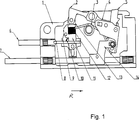
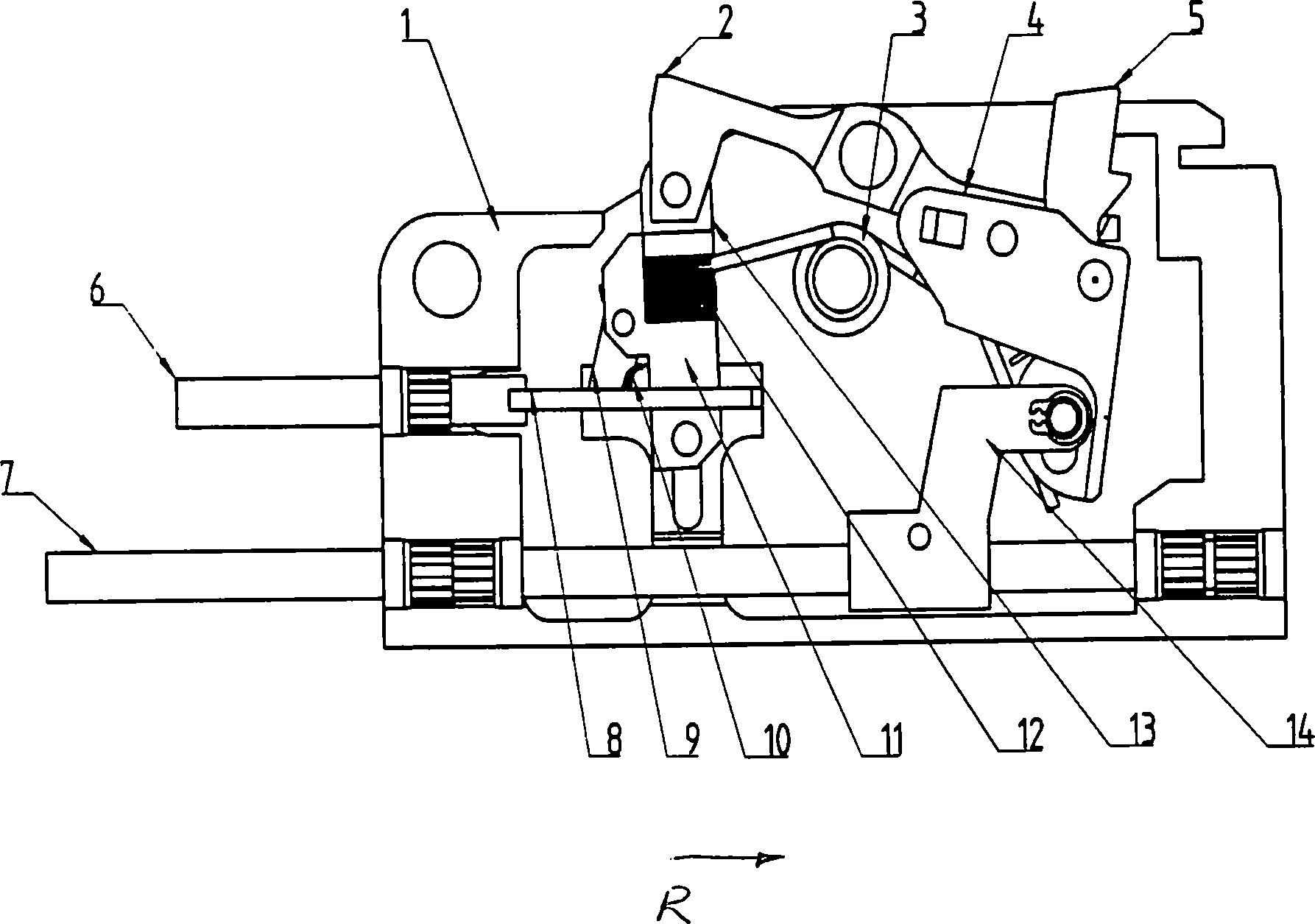
In
Mit dem Verschlussfanghebel
Die Funktion ist wie folgt:
Die Waffe (nicht näher dargestellt) wird entsichert, in dem das Sicherungsgestänge
The weapon (not shown) is unlocked, in which the safety linkage
Um einer Beschädigung der Waffe vorzubeugen, kann der Verschlussfanghebel
Die Betätigung der beiden Gestänge
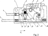
Die
Das Maschinengriffstück
Die Funktion dieses Maschinengriffstücks
Wird die Führungsstange
Ein Kabelbruch am Sicherungsaktor, welcher auch hier an der Führungsstange (
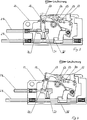
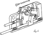
Über zumindest einen, nicht näher dargestellten Sensor kann die Position des Sicherungsgestänges
Läuft der Verschluss der Waffe von vorne über den Verschlussfanghebel
Erschütterungen, Schläge oder Stöße können die Sicherung nicht lösen, da der eingerastete Verschluss selbst die (mechanische) Verriegelungsklinke
Es wird sichergestellt, dass der Verschluss der Waffe immer gefangen wird, egal welcher der Aktoren, der zur Bedienung des Maschinengriffstückes gehört, ausfällt.It is ensured that the lock of the weapon is always caught, no matter which of the actuators, which belongs to the operation of the machine grip, fails.
Ein ähnlicher Funktionsablauf bzw. die entsprechenden Bedingungen treffen auch für die Ausführung nach
Claims (3)
Priority Applications (1)
| Application Number | Priority Date | Filing Date | Title |
|---|---|---|---|
| DE102008009827.2A DE102008009827B4 (en) | 2007-10-08 | 2008-02-18 | Safety mechanism for weapons |
Applications Claiming Priority (3)
| Application Number | Priority Date | Filing Date | Title |
|---|---|---|---|
| DE102007048292.4 | 2007-10-08 | ||
| DE102007048292 | 2007-10-08 | ||
| DE102008009827.2A DE102008009827B4 (en) | 2007-10-08 | 2008-02-18 | Safety mechanism for weapons |
Publications (2)
| Publication Number | Publication Date |
|---|---|
| DE102008009827A1 DE102008009827A1 (en) | 2009-04-09 |
| DE102008009827B4 true DE102008009827B4 (en) | 2014-10-16 |
Family
ID=40418271
Family Applications (2)
| Application Number | Title | Priority Date | Filing Date |
|---|---|---|---|
| DE102008009827.2A Expired - Fee Related DE102008009827B4 (en) | 2007-10-08 | 2008-02-18 | Safety mechanism for weapons |
| DE502008003041T Active DE502008003041D1 (en) | 2007-10-08 | 2008-10-08 | SECURITY MECHANISM FOR A FISHING LEVER |
Family Applications After (1)
| Application Number | Title | Priority Date | Filing Date |
|---|---|---|---|
| DE502008003041T Active DE502008003041D1 (en) | 2007-10-08 | 2008-10-08 | SECURITY MECHANISM FOR A FISHING LEVER |
Country Status (9)
| Country | Link |
|---|---|
| US (1) | US8042450B2 (en) |
| EP (1) | EP2198232B1 (en) |
| KR (1) | KR101284930B1 (en) |
| AT (1) | ATE503978T1 (en) |
| AU (1) | AU2008309924B2 (en) |
| DE (2) | DE102008009827B4 (en) |
| ES (1) | ES2362977T3 (en) |
| PT (1) | PT2198232E (en) |
| WO (1) | WO2009046968A1 (en) |
Families Citing this family (9)
| Publication number | Priority date | Publication date | Assignee | Title |
|---|---|---|---|---|
| US7559269B2 (en) | 2001-12-14 | 2009-07-14 | Irobot Corporation | Remote digital firing system |
| US8375838B2 (en) * | 2001-12-14 | 2013-02-19 | Irobot Corporation | Remote digital firing system |
| DE102009057569B3 (en) * | 2009-12-09 | 2010-12-02 | Blaser Finanzholding Gmbh | Clamping device for lock of repeating rifle, has detent combined with counter detent for holding clamping bolts in front clamping position, and declamping mechanisms attached to bolts for declamping striker spring during removal of magazine |
| DE102011106200B4 (en) | 2011-06-07 | 2016-03-17 | Rheinmetall Air Defence Ag | Firing pin safety |
| DE102012212388B4 (en) * | 2012-07-16 | 2014-08-28 | Heckler & Koch Gmbh | Trigger assembly for a firearm |
| IL223982A (en) * | 2012-12-27 | 2016-12-29 | Rafael Advanced Defense Systems Ltd | Firing preventing and stoppage apparatus for remotely operated automatic weapon |
| US10704853B2 (en) * | 2018-08-24 | 2020-07-07 | WHG Properties, LLC | Trigger assemblies for firearms |
| US10982920B1 (en) | 2019-11-12 | 2021-04-20 | Kudzu Arms, Llc | Wireless firearm mechanism and associated accessories |
| DE102021103878B8 (en) | 2021-02-18 | 2022-06-23 | Heckler & Koch Gmbh | Control element, bolt catch, bolt carrier, trigger, trigger assembly for a machine gun and machine gun equipped therewith |
Citations (7)
| Publication number | Priority date | Publication date | Assignee | Title |
|---|---|---|---|---|
| DE1203164B (en) * | 1961-02-13 | 1965-10-14 | Oerlikon Buehrle Holding A G | Trigger device on an automatic firearm |
| DE2323352A1 (en) * | 1973-05-09 | 1974-11-21 | Rheinmetall Gmbh | EXTRACTOR FOR AUTOMATIC FIRE ARMS |
| DE2511765A1 (en) * | 1975-03-18 | 1976-09-23 | Heckler & Koch Gmbh | Light action trigger mechanism for automatic cannon - has breech block catch lever actuated by pivoted leaf spring |
| DE2742241A1 (en) * | 1977-09-20 | 1979-03-22 | Rheinmetall Gmbh | SERVO TRIGGER FOR A MACHINE WEAPON, IN PARTICULAR MACHINE CANNON |
| DE3103864A1 (en) * | 1981-02-05 | 1982-09-02 | Rheinmetall GmbH, 4000 Düsseldorf | Fume cupboard for an automatic firearm with a straight lock |
| EP0123871A1 (en) * | 1983-04-29 | 1984-11-07 | Werkzeugmaschinenfabrik Oerlikon-Bührle AG | Trigger mechanism for an automatic gun |
| DE10163003A1 (en) * | 2001-12-20 | 2003-07-17 | Heckler & Koch Gmbh | Trigger device for a rapid-fire handgun |
Family Cites Families (8)
| Publication number | Priority date | Publication date | Assignee | Title |
|---|---|---|---|---|
| US4133128A (en) | 1977-08-18 | 1979-01-09 | Brush Clyde E | Safety device for rifles |
| US4475437A (en) * | 1980-12-11 | 1984-10-09 | Chartered Industries Of Singapore Private Limited | Sear actuator |
| US4730538A (en) | 1986-04-03 | 1988-03-15 | Star Bonifacio Echeverria, S.A. | Safety device for automatic firearms |
| AU3549893A (en) * | 1992-08-19 | 1994-02-24 | Edward Karl Felk | An automatic pistol with select fire mechanism |
| EP0936435A1 (en) * | 1998-02-17 | 1999-08-18 | Franchi S.p.A. | Permanently safety device for preventing the accidental firing of a firearm |
| US6718680B2 (en) * | 2000-03-20 | 2004-04-13 | Albert Roca | Semiautomatic handgun having multiple safeties |
| US7743543B2 (en) * | 2005-10-06 | 2010-06-29 | Theodore Karagias | Trigger mechanism and a firearm containing the same |
| DE102007052105B3 (en) * | 2007-10-31 | 2009-05-28 | Heckler & Koch Gmbh | Catch, trigger and handle for a weapon |
-
2008
- 2008-02-18 DE DE102008009827.2A patent/DE102008009827B4/en not_active Expired - Fee Related
- 2008-10-08 WO PCT/EP2008/008486 patent/WO2009046968A1/en not_active Ceased
- 2008-10-08 KR KR1020107007611A patent/KR101284930B1/en not_active Expired - Fee Related
- 2008-10-08 AT AT08837267T patent/ATE503978T1/en active
- 2008-10-08 DE DE502008003041T patent/DE502008003041D1/en active Active
- 2008-10-08 ES ES08837267T patent/ES2362977T3/en active Active
- 2008-10-08 AU AU2008309924A patent/AU2008309924B2/en not_active Ceased
- 2008-10-08 EP EP08837267A patent/EP2198232B1/en not_active Not-in-force
- 2008-10-08 PT PT08837267T patent/PT2198232E/en unknown
-
2010
- 2010-04-08 US US12/756,860 patent/US8042450B2/en not_active Expired - Fee Related
Patent Citations (7)
| Publication number | Priority date | Publication date | Assignee | Title |
|---|---|---|---|---|
| DE1203164B (en) * | 1961-02-13 | 1965-10-14 | Oerlikon Buehrle Holding A G | Trigger device on an automatic firearm |
| DE2323352A1 (en) * | 1973-05-09 | 1974-11-21 | Rheinmetall Gmbh | EXTRACTOR FOR AUTOMATIC FIRE ARMS |
| DE2511765A1 (en) * | 1975-03-18 | 1976-09-23 | Heckler & Koch Gmbh | Light action trigger mechanism for automatic cannon - has breech block catch lever actuated by pivoted leaf spring |
| DE2742241A1 (en) * | 1977-09-20 | 1979-03-22 | Rheinmetall Gmbh | SERVO TRIGGER FOR A MACHINE WEAPON, IN PARTICULAR MACHINE CANNON |
| DE3103864A1 (en) * | 1981-02-05 | 1982-09-02 | Rheinmetall GmbH, 4000 Düsseldorf | Fume cupboard for an automatic firearm with a straight lock |
| EP0123871A1 (en) * | 1983-04-29 | 1984-11-07 | Werkzeugmaschinenfabrik Oerlikon-Bührle AG | Trigger mechanism for an automatic gun |
| DE10163003A1 (en) * | 2001-12-20 | 2003-07-17 | Heckler & Koch Gmbh | Trigger device for a rapid-fire handgun |
Also Published As
| Publication number | Publication date |
|---|---|
| KR20100081311A (en) | 2010-07-14 |
| EP2198232B1 (en) | 2011-03-30 |
| US8042450B2 (en) | 2011-10-25 |
| KR101284930B1 (en) | 2013-07-10 |
| ATE503978T1 (en) | 2011-04-15 |
| EP2198232A1 (en) | 2010-06-23 |
| AU2008309924A1 (en) | 2009-04-16 |
| DE102008009827A1 (en) | 2009-04-09 |
| AU2008309924B2 (en) | 2011-06-30 |
| PT2198232E (en) | 2011-04-13 |
| WO2009046968A1 (en) | 2009-04-16 |
| DE502008003041D1 (en) | 2011-05-12 |
| ES2362977T3 (en) | 2011-07-18 |
| US20100257769A1 (en) | 2010-10-14 |
Similar Documents
| Publication | Publication Date | Title |
|---|---|---|
| DE102008009827B4 (en) | Safety mechanism for weapons | |
| EP2406574B1 (en) | Externally and also independently operated weapon | |
| EP3591329B1 (en) | Weapon handle or weapon housing for a self-loading firearm with a breech block catch and self-loading firearm comprising such a weapon handle or weapon housing | |
| EP3087338A1 (en) | Device for preventing tensioning of a firing pin spring when disarming a hammerless automatic pistol provided with a lock slide, and automatic pistol with such a device | |
| DE102020125592A1 (en) | Straight-pull bolt for repeating weapons and repeating weapon with this | |
| DE2745670A1 (en) | TRIGGER SAFETY FOR GUNS | |
| DE2754761C2 (en) | "Trigger device for a semi-automatic firearm" | |
| DE19732857C1 (en) | Safety action e.g. for rifle | |
| AT515918B1 (en) | DEFLECTION DEVICE FOR A SEMI-AUTOMATIC HAND FIREARM | |
| DE69429352T2 (en) | FIREARMS WITH OFFSET CAM MECHANISM | |
| DE102011106200B4 (en) | Firing pin safety | |
| DE3035796C2 (en) | ||
| DE112022004930T5 (en) | Firearm | |
| EP2049863B1 (en) | Apparatus for releasing a firing pin | |
| WO2017102842A1 (en) | Cocking device for a firing pin and weapon comprising said cocking device | |
| EP2216616B1 (en) | Safety device for a mounted weapon | |
| DE1944625A1 (en) | Grenade launcher attachable to a handgun | |
| DE139766C (en) | Automatic firearm with sliding barrel | |
| DE1166052B (en) | Emergency device with insert barrel for firing small caliber ammunition with automatic handguns, especially assault rifles with hammer ignition | |
| DE1148470B (en) | Automatic firearm with a changeover device for single and continuous fire | |
| DE78615C (en) | An embodiment of the automatic firearm with cylinder lock protected by patent no. 76990 | |
| DE112022004961T5 (en) | Firearm | |
| WO2026068691A1 (en) | Straight-pull repeating rifle | |
| DE215490C (en) | ||
| DE2136101C3 (en) | Shot counter for automatic firearms with hammer ignition |
Legal Events
| Date | Code | Title | Description |
|---|---|---|---|
| R012 | Request for examination validly filed |
Effective date: 20131105 |
|
| R016 | Response to examination communication | ||
| R018 | Grant decision by examination section/examining division | ||
| R020 | Patent grant now final | ||
| R119 | Application deemed withdrawn, or ip right lapsed, due to non-payment of renewal fee |