DE102007061358B4 - Device for shaping laser radiation - Google Patents
Device for shaping laser radiation Download PDFInfo
- Publication number
- DE102007061358B4 DE102007061358B4 DE102007061358A DE102007061358A DE102007061358B4 DE 102007061358 B4 DE102007061358 B4 DE 102007061358B4 DE 102007061358 A DE102007061358 A DE 102007061358A DE 102007061358 A DE102007061358 A DE 102007061358A DE 102007061358 B4 DE102007061358 B4 DE 102007061358B4
- Authority
- DE
- Germany
- Prior art keywords
- interface
- refractive
- laser radiation
- partial beams
- refractive interface
- Prior art date
- Legal status (The legal status is an assumption and is not a legal conclusion. Google has not performed a legal analysis and makes no representation as to the accuracy of the status listed.)
- Expired - Fee Related
Links
Images

Classifications
-
- G—PHYSICS
- G02—OPTICS
- G02B—OPTICAL ELEMENTS, SYSTEMS OR APPARATUS
- G02B19/00—Condensers, e.g. light collectors or similar non-imaging optics
- G02B19/0033—Condensers, e.g. light collectors or similar non-imaging optics characterised by the use
- G02B19/0047—Condensers, e.g. light collectors or similar non-imaging optics characterised by the use for use with a light source
- G02B19/0052—Condensers, e.g. light collectors or similar non-imaging optics characterised by the use for use with a light source the light source comprising a laser diode
- G02B19/0057—Condensers, e.g. light collectors or similar non-imaging optics characterised by the use for use with a light source the light source comprising a laser diode in the form of a laser diode array, e.g. laser diode bar
-
- G—PHYSICS
- G02—OPTICS
- G02B—OPTICAL ELEMENTS, SYSTEMS OR APPARATUS
- G02B19/00—Condensers, e.g. light collectors or similar non-imaging optics
- G02B19/0004—Condensers, e.g. light collectors or similar non-imaging optics characterised by the optical means employed
- G02B19/0009—Condensers, e.g. light collectors or similar non-imaging optics characterised by the optical means employed having refractive surfaces only
- G02B19/0014—Condensers, e.g. light collectors or similar non-imaging optics characterised by the optical means employed having refractive surfaces only at least one surface having optical power
-
- G—PHYSICS
- G02—OPTICS
- G02B—OPTICAL ELEMENTS, SYSTEMS OR APPARATUS
- G02B27/00—Optical systems or apparatus not provided for by any of the groups G02B1/00 - G02B26/00, G02B30/00
- G02B27/09—Beam shaping, e.g. changing the cross-sectional area, not otherwise provided for
- G02B27/0938—Using specific optical elements
- G02B27/095—Refractive optical elements
- G02B27/0955—Lenses
- G02B27/0966—Cylindrical lenses
Abstract
Vorrichtung zur Formung von Laserstrahlung, die in einer ersten, zu der Ausbreitungsrichtung (Z) der Laserstrahlung senkrechten Richtung (X) zueinander beabstandete Teilstrahlen (3) aufweist, umfassend – eine erste refraktive Grenzfläche (8), die zumindest eine Mehrzahl der Teilstrahlen (3) der zu formenden Laserstrahlung derart unterschiedlich ablenken kann, dass sie nach Hindurchtritt durch die erste Grenzfläche (8) zumindest teilweise konvergenter zueinander verlaufen, als vor dem Hindurchtritt durch die erste Grenzfläche (8), sowie – eine zweite refraktive Grenzfläche (9), durch die die durch die erste Grenzfläche (8) hindurch getretene Laserstrahlung hindurch treten kann, wobei die zweite Grenzfläche (9) zumindest einige der Teilstrahlen (3) derart ablenken kann, dass deren Konvergenz verringert wird, wobei – die erste und/oder die zweite der refraktiven Grenzflächen (8, 9) jeweils eine Mehrzahl von zueinander geneigten Flächen (14, 17) aufweisen, die zumindest teilweise in der ersten Richtung (X) aneinander anschließen, dadurch gekennzeichnet, dass die zueinander geneigten...A device for shaping laser radiation which has partial beams (3) spaced apart from one another in a first direction (X) perpendicular to the direction of propagation (Z) of the laser radiation, comprising - a first refractive interface (8) which at least a plurality of the partial beams (3 ) can deflect the laser radiation to be shaped differently in such a way that after passing through the first interface (8) they are at least partially more convergent to one another than before passing through the first interface (8), and - a second refractive interface (9) through which the laser radiation that has passed through the first interface (8) can pass through, wherein the second interface (9) can deflect at least some of the partial beams (3) in such a way that their convergence is reduced, the first and / or the second of the refractive interfaces (8, 9) each have a plurality of mutually inclined surfaces (14, 17) which are at least partially in the in the first direction (X), characterized in that the ...
Description
Die vorliegende Erfindung betrifft eine Vorrichtung zur Formung von Laserstrahlung gemäß dem Oberbegriff des Anspruchs 1.The present invention relates to a device for shaping laser radiation according to the preamble of
Definitionen: In Ausbreitungsrichtung des zu beeinflussenden Lichts meint die mittlere Ausbreitungsrichtung des Lichts, insbesondere wenn dieses keine ebene Welle ist oder zumindest teilweise konvergent oder divergent ist. Mit Lichtstrahl, Teilstrahl oder Strahl ist, wenn nicht ausdrücklich anderes angegeben ist, kein idealisierter Strahl der geometrischen Optik gemeint, sondern ein realer Lichtstrahl, wie beispielsweise ein Laserstrahl mit einem Gauß-Profil, der keinen infinitesimal kleinen, sondern einen ausgedehnten Strahlquerschnitt aufweist.Definitions: In the propagation direction of the light to be influenced, the mean propagation direction of the light means, especially if this is not a plane wave or at least partially convergent or divergent. By light beam, sub-beam or beam is meant, unless expressly stated otherwise, an idealized beam of geometric optics, but a real light beam, such as a laser beam with a Gaussian profile, which has no infinitesimal small, but an extended beam cross-section.
Eine Vorrichtung der eingangs genannten Art ist insbesondere zur Formung von Laserstrahlung, die von einem Laserdiodenbarren ausgeht, geeignet. Laserdiodenbarren weisen eine Mehrzahl von Emittern, beispielsweise 19 Emitter auf, die in der sogenannten Slow-Axis beabstandet zueinander angeordnet sind. Die Slow-Axis ist die eingangs genannte erste Richtung, in der sich die aktive Schicht der Halbleiterdiode erstreckt, wohingegen die Fast-Axis die dazu senkrechte Richtung ist. Beispielsweise weist ein jeder der Emitter eine Länge von etwa 150 μm in der Slow-Axis auf, wobei der Abstand zweier benachbarter Emitter zueinander in dieser Richtung etwa 400 μm beträgt. Das hat zur Folge, dass zwischen den von den einzelnen Emittern ausgehenden Teilstrahlen Dunkelbereiche vorhanden sind, die sich als nachteilig für die Brightness (spezifische Intensität) der Laserstrahlung erweisen.A device of the type mentioned in particular is suitable for shaping laser radiation emanating from a laser diode bar. Laser diode bars have a plurality of emitters, for example 19 emitters, which are arranged at a distance from one another in the so-called slow axis. The slow axis is the first direction mentioned at the beginning, in which the active layer of the semiconductor diode extends, whereas the fast axis is the direction perpendicular thereto. For example, each of the emitters has a length of about 150 .mu.m in the slow axis, wherein the distance between two adjacent emitters to each other in this direction is about 400 microns. As a result, dark areas are present between the sub-beams emanating from the individual emitters, which are disadvantageous for the brightness (specific intensity) of the laser radiation.
Im Stand der Technik werden die von den einzelnen Emittern ausgehenden Teilstrahlen der Laserdiodenbarren durch Mikrooptiken in der Fast-Axis und zum Teil auch in der Slow-Axis kollimiert, ohne dass dabei die Periodizität der Strahlen der einzelnen Emitter manipuliert wird. Ein Beispiel dafür findet sich in der
Ein weiteres Beispiel für eine strahlformende Optik findet sich in der
Eine Vorrichtung der eingangs genannten Art ist aus der
Eine weitere Vorrichtung zur Formung des von einem Laserdiodenbarren ausgehenden Lichts ist aus der
Das der vorliegenden Erfindung zugrunde liegende Problem ist die Schaffung einer Vorrichtung der eingangs genannten Art, mit der die von einem Laserdiodenbarren ausgehende Laserstrahlung derart geformt werden kann, dass sie eine größere Brightness aufweist und/oder sich besser fokussieren lässt.The problem underlying the present invention is to provide a device of the type mentioned above, with which the laser radiation emanating from a laser diode bar can be shaped such that it has a greater brightness and / or can be focused better.
Dies wird erfindungsgemäß durch eine Vorrichtung mit den Merkmalen des Anspruchs 1 erreicht. Die Unteransprüche betreffen bevorzugte Ausführungsformen der vorliegenden Erfindung.This is inventively achieved by a device having the features of
Gemäß Anspruch 1 ist vorgesehen, dass die zueinander geneigten Flächen auf mindestens einer zylindrischen Kontur angeordnet sind und dass der Absolutwert der Differenz zwischen 180° und den Winkeln zwischen den Flächen in der ersten Richtung von den äußeren Randbereichen der mindestens einen zylindrischen Kontur zu der Mitte der mindestens einen zylindrischen Kontur abnimmt. Dabei kann durch Verringerung oder Eliminierung des Abstands zwischen den Teilsstrahlen in der ersten Richtung der Dunkelbereich zwischen den einzelnen Teilstrahlen verkleinert werden, so dass die erzielbare Brightness näher an die physikalische Grenze gebracht werden kann.According to
Es kann vorgesehen sein, dass die erste refraktive Grenzfläche zumindest eine Mehrzahl der Teilstrahlen der zu formenden Laserstrahlung derart unterschiedlich ablenken kann, dass sie nach dem Hindurchtritt durch die erste refraktive Grenzfläche auf einen Punkt ausgerichtet sind, der in Ausbreitungsrichtung der Laserstrahlung hinter der zweiten refraktiven Grenzfläche angeordnet ist.It can be provided that the first refractive interface can deflect at least a majority of the partial beams of the laser radiation to be shaped in such a different way that they are aligned after passing through the first refractive interface to a point which is in the propagation direction of the laser radiation behind the second refractive interface is arranged.
Weiterhin kann vorgesehen sein, dass die Vorrichtung Kollimationsmittel umfasst, die die Laserstrahlung hinsichtlich der ersten Richtung und/oder hinsichtlich einer zweiten, zu der ersten Richtung und zu der Ausbreitungsrichtung der Laserstrahlung senkrechten Richtung zumindest teilweise kollimieren können, wobei insbesondere die Kollimationsmittel in Ausbreitungsrichtung der Laserstrahlung vor der ersten refraktiven Grenzfläche angeordnet sind.Furthermore, it can be provided that the device comprises collimation means which can at least partially collimate the laser radiation with respect to the first direction and / or with respect to a second direction perpendicular to the first direction and to the propagation direction of the laser radiation, in particular the collimation means in the propagation direction of the laser radiation are arranged in front of the first refractive interface.
Insbesondere kann dabei die zweite Grenzfläche zumindest einige der Teilstrahlen derart ablenken, dass die Konvergenz der Teilstrahlen derart verringert wird, dass sie mit Abweichungen von ±10%, vorzugsweise ±5%, insbesondere von ±1% parallel zueinander verlaufen. Die einzelnen Teilstrahlen können somit nach dem Hindurchtritt durch die zweite refraktive Grenzfläche wieder parallel sein, wobei Periodizität und Dunkelbereich manipuliert sind. Dadurch wird eine höhere Brightness erzielt, als das mit den bisher erhältlichen Optiken möglich ist.In particular, the second interface may deflect at least some of the partial beams in such a way that the convergence of the partial beams is reduced in such a way that they run parallel to one another with deviations of ± 10%, preferably ± 5%, in particular ± 1%. The individual partial beams can thus be parallel again after passing through the second refractive interface, the periodicity and the dark range being manipulated. This results in a higher brightness than is possible with the previously available optics.
Es besteht die Möglichkeit, dass durch jede der Flächen mindestens einer der Teilstrahlen hindurchtreten kann. Dadurch werden einzelne der Teilstrahlen, insbesondere sämtliche Teilstrahlen unter voneinander verschiedenen Winkeln gebrochen. Beispielsweise können sich die Ablenkwinkel der durch die einzelnen Flächen der ersten refraktiven Grenzfläche hindurch getretenen Teilstrahlen derart unterscheiden, dass sämtliche Teilstrahlen nach dem Hindurchtritt durch die erste refraktive Grenzfläche auf einen Punkt ausgerichtet sind, der in Ausbreitungsrichtung der Laserstrahlung hinter der zweiten refraktiven Grenzfläche angeordnet ist. Insbesondere können sich die Ablenkwinkel der durch die einzelnen Flächen der zweiten refraktiven Grenzfläche hindurch getretenen Teilstrahlen derart unterscheiden, dass sämtliche Teilstrahlen nach dem Hindurchtritt durch die zweite refraktive Grenzfläche parallel zueinander verlaufen, wobei dabei insbesondere der Abstand zwischen den Teilsstrahlen in der ersten Richtung verkleinert wurde oder im wesentlichen nicht mehr vorhanden ist.There is a possibility that at least one of the partial beams may pass through each of the surfaces. As a result, individual of the partial beams, in particular all partial beams are broken at different angles. For example, the deflection angles of the partial beams that have passed through the individual surfaces of the first refractive boundary surface may differ such that all partial beams after passing through the first refractive boundary surface are aligned with a point which is arranged behind the second refractive boundary surface in the propagation direction of the laser radiation. In particular, the deflection angles of the partial beams that have passed through the individual surfaces of the second refractive interface may differ such that all partial beams extend parallel to one another after passing through the second refractive interface, in which case the distance between the partial beams in the first direction has been reduced or essentially no longer exists.
Die zueinander geneigten Flächen können zumindest teilweise plan sein.The mutually inclined surfaces may be at least partially planar.
Insbesondere kann vorgesehen sein, dass die mindestens eine zylindrische Kontur auf der ersten refraktiven Grenzfläche konvex geformt ist. Dabei kann dann die mindestens eine zylindrische Kontur auf der zweiten refraktiven Grenzfläche konkav geformt sein. Dadurch ergibt sich eine Entsprechung der brechenden Winkel der planen Flächen auf der ersten und der zweiten refraktiven Grenzfläche. Insbesondere können die in der ersten Richtung aneinander anschließen Flächen der ersten refraktiven Grenzfläche zumindest teilweise einen Winkel zwischen 150° und 180°, insbesondere einen Winkel zwischen 165° und 180°, vorzugsweise einen Winkel zwischen 175° und 179° miteinander einschließen. Entsprechend können die in der ersten Richtung aneinander anschließenden Flächen der zweiten refraktiven Grenzfläche zumindest teilweise einen Winkel zwischen 180° und 210°, insbesondere einen Winkel zwischen 180° und 195°, vorzugsweise einen Winkel zwischen 181° und 185° miteinander einschließen. Die zweite refraktive Grenzfläche weist dabei insbesondere die gleiche Anzahl planer Flächen auf, die so ausgerichtet sind, dass sie die einzelnen Teilstrahlen verglichen mit der ersten refraktiven Grenzfläche unter dem jeweils negativen Winkel brechen, bevor sie den Punkt erreichen, auf den sie ausgerichtet sind.In particular, it can be provided that the at least one cylindrical contour is convexly shaped on the first refractive interface. In this case, the at least one cylindrical contour can then be concave on the second refractive interface. This results in a correspondence of the refractive angles of the flat surfaces on the first and second refractive interfaces. In particular, the surfaces of the first refractive interface adjoining one another in the first direction may at least partially enclose an angle between 150 ° and 180 °, in particular an angle between 165 ° and 180 °, preferably an angle between 175 ° and 179 °. Accordingly, the adjoining in the first direction surfaces of the second refractive interface at least partially an angle between 180 ° and 210 °, in particular an angle between 180 ° and 195 °, preferably include an angle between 181 ° and 185 ° with each other. In particular, the second refractive interface has the same number of planar surfaces which are oriented so that they break the individual partial beams at the respectively negative angle compared with the first refractive interface before they reach the point to which they are aligned.
Alternativ dazu kann vorgesehen sein, dass die Winkel zwischen den planen Flächen auf der ersten refraktiven Grenzfläche unterschiedlich zu den Winkeln zwischen den planen Flächen auf der zweiten refraktiven Grenzfläche sind. Damit trotzdem die Ablenkwinkel der Teilstrahlen bei der ersten und der zweiten Grenzfläche einander entsprechen, kann der Brechungsindex des Materials, in dem die erste Grenzfläche geformt ist, unterschiedlich zu dem Brechungsindex des Materials sein, in dem die zweite Grenzfläche geformt ist.Alternatively, it can be provided that the angles between the planar surfaces on the first refractive interface are different from the angles between the planar surfaces on the second refractive interface. In spite of the fact that the deflection angles of the partial beams at the first and second interfaces correspond to each other, the refractive index of the material in which the first interface is formed may be different than the refractive index of the material in which the second interface is formed.
Weiterhin besteht die Möglichkeit, dass die erste und/oder die zweite der refraktiven Grenzflächen mindestens zwei Gruppen von zueinander geneigten Flächen aufweisen, wobei jede der Gruppen auf einer eigenen zylindrischen Kontur angeordnet ist.Furthermore, there is the possibility that the first and / or the second of the refractive interfaces have at least two groups of mutually inclined surfaces, wherein each of the groups is arranged on its own cylindrical contour.
Es kann weiterhin vorgesehen sein, dass die mindestens zwei zylindrischen Konturen auf der ersten refraktiven Grenzfläche in der ersten Richtung nebeneinander angeordnet sind.It may further be provided that the at least two cylindrical contours are arranged next to one another on the first refractive interface in the first direction.
Die mindestens zwei zylindrischen Konturen auf der zweiten refraktiven Grenzfläche können in der ersten Richtung voneinander beabstandet sein. Dadurch besteht die Möglichkeit, die Teilstrahlen in zwei separaten Gruppen zusammenzufassen, die dann beispielsweise durch eine geometrische Kopplung, eine Polarisationskopplung oder eine Wellenlängenkopplung kompakt überlagert werden können, um die Formung eines symmetrischen Strahlprofils als Ziel zu unterstützen. Ein solches Profil ist beispielsweise für die Einkoppelung der Laserstrahlung in Lichtleitfasern geeignet, die eine ebenfalls symmetrische Stirnfläche aufweisen.The at least two cylindrical contours on the second refractive interface may be spaced apart in the first direction. This makes it possible to combine the sub-beams in two separate groups, which can then be compactly superimposed, for example by a geometric coupling, a polarization coupling or a wavelength coupling to the formation of a symmetrical beam profile as a target to support. Such a profile is suitable for example for the coupling of the laser radiation in optical fibers, which also have a symmetrical end face.
Wie erwähnt verwenden bisherige Lösungen für die Aufteilung eine separate Optik. Durch die erfindungsgemäß Vorrichtung entfällt eine solche separate Optik, die nur die Aufgabe verfolgte, die Einzelstrahlen in zwei oder mehr Gruppen aufzuteilen. Vielmehr kann bei der erfindungsgemäßen Vorrichtung die Erhöhung der Brightness durch Eliminierung der Dunkelbereiche mit der Aufteilung der Teilstrahlen in Gruppen kombiniert werden. Die Ergebnisse dieser zweiten Funktion sind ein kürzerer Strahlengang und eine Verringerung der Komplexität. Möglich ist die Herstellung von fasergekoppelten Lasersystemen mit Fasern von 50 μm Kerndurchmesser und einer numerischen Apertur (NA) = 0,22 oder 100 μm Kerndurchmesser und einer NA = 0,12 bei der Verwendung von Laserdiodenbarren mit Breitstreifenemittern (BALG) als Lichtquelle. Die Erweiterung auf Mehrbarrensysteme ist ebenfalls möglich.As mentioned, previous solutions for partitioning use a separate look. By means of the device according to the invention, such a separate optical system is omitted, which only pursued the task of dividing the individual beams into two or more groups. Rather, in the device according to the invention, the increase in brightness can be combined by eliminating the dark areas with the division of the partial beams into groups. The results of this second function are a shorter beam path and a reduction in complexity. It is possible to produce fiber-coupled laser systems with fibers of 50 μm core diameter and a numerical aperture (NA) = 0.22 or 100 μm core diameter and a NA = 0.12 when using laser diode bars with wide-band emitters (BALG) as the light source. The extension to multi-bar systems is also possible.
Es besteht die Möglichkeit, dass die Vorrichtung zwei Substrate umfasst, die in Ausbreitungsrichtung der Laserstrahlung hintereinander, insbesondere voneinander beabstandet, angeordnet sind.There is the possibility that the device comprises two substrates, which are arranged one behind the other in the propagation direction of the laser radiation, in particular spaced apart from one another.
Weiterhin kann vorgesehen sein, dass auf jedem der Substrate eine der refraktiven Grenzflächen angeordnet ist.Furthermore, it can be provided that one of the refractive interfaces is arranged on each of the substrates.
Dabei kann die erste refraktive Grenzfläche die Eintrittsfläche des ersten Substrates sein und/oder kann die zweite refraktive Grenzfläche die Austrittsfläche des zweiten Substrates sein.In this case, the first refractive interface may be the entrance surface of the first substrate and / or the second refractive interface may be the exit surface of the second substrate.
Weiterhin können die Austrittsfläche des ersten Substrates plan und/oder dass die Eintrittsfläche des zweiten Substrates plan sein.Furthermore, the exit surface of the first substrate may be flat and / or the entrance surface of the second substrate may be flat.
Weitere Merkmale und Vorteile der vorliegenden Erfindung werden deutlich anhand der nachfolgenden Beschreibung bevorzugter Ausführungsbeispiele unter Bezugnahme auf die beiliegenden Abbildungen. Darin zeigenFurther features and advantages of the present invention will become apparent from the following description of preferred embodiments with reference to the accompanying drawings. Show in it
In den Figuren sind zur besseren Orientierung kartesische Koordinatensysteme eingezeichnet.In the figures, Cartesian coordinate systems are shown for better orientation.
In
Die aus
In Ausbreitungsrichtung Z hinter der Fast-Axis-Kollimationslinse
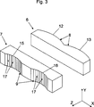
In Ausbreitungsrichtung Z hinter der Strahltransformationsvorrichtung
Die als Eintrittsfläche des ersten Substrats
Die als Austrittsfläche des zweiten Substrats
Dem Vergleich von
Hinter den beiden Substraten
Claims (18)
Priority Applications (6)
| Application Number | Priority Date | Filing Date | Title |
|---|---|---|---|
| DE102007061358A DE102007061358B4 (en) | 2007-12-19 | 2007-12-19 | Device for shaping laser radiation |
| EP08020687A EP2073051A3 (en) | 2007-12-19 | 2008-11-28 | Device for shaping laser radiation |
| KR1020080124380A KR101671332B1 (en) | 2007-12-19 | 2008-12-09 | Device for shaping laser radiation |
| US12/336,143 US7986461B2 (en) | 2007-12-19 | 2008-12-16 | Device for shaping laser radiation |
| CN2008101852198A CN101464563B (en) | 2007-12-19 | 2008-12-18 | Device for shaping laser radiation |
| JP2008324542A JP5507837B2 (en) | 2007-12-19 | 2008-12-19 | Apparatus for forming a laser beam |
Applications Claiming Priority (1)
| Application Number | Priority Date | Filing Date | Title |
|---|---|---|---|
| DE102007061358A DE102007061358B4 (en) | 2007-12-19 | 2007-12-19 | Device for shaping laser radiation |
Publications (2)
| Publication Number | Publication Date |
|---|---|
| DE102007061358A1 DE102007061358A1 (en) | 2009-07-02 |
| DE102007061358B4 true DE102007061358B4 (en) | 2012-02-16 |
Family
ID=40467125
Family Applications (1)
| Application Number | Title | Priority Date | Filing Date |
|---|---|---|---|
| DE102007061358A Expired - Fee Related DE102007061358B4 (en) | 2007-12-19 | 2007-12-19 | Device for shaping laser radiation |
Country Status (6)
| Country | Link |
|---|---|
| US (1) | US7986461B2 (en) |
| EP (1) | EP2073051A3 (en) |
| JP (1) | JP5507837B2 (en) |
| KR (1) | KR101671332B1 (en) |
| CN (1) | CN101464563B (en) |
| DE (1) | DE102007061358B4 (en) |
Families Citing this family (8)
| Publication number | Priority date | Publication date | Assignee | Title |
|---|---|---|---|---|
| DE102008027231B4 (en) * | 2008-06-06 | 2016-03-03 | Limo Patentverwaltung Gmbh & Co. Kg | Apparatus for beam shaping |
| WO2010084001A1 (en) | 2009-01-23 | 2010-07-29 | Limo Patentverwaltung Gmbh & Co. Kg | Beam forming device for laser diode arrays |
| US9214368B2 (en) * | 2011-07-27 | 2015-12-15 | Ipg Photonics Corporation | Laser diode array with fiber optic termination for surface treatment of materials |
| DE102012107456A1 (en) | 2012-08-14 | 2014-02-20 | Limo Patentverwaltung Gmbh & Co. Kg | Arrangement for shaping laser radiation |
| US10203399B2 (en) | 2013-11-12 | 2019-02-12 | Big Sky Financial Corporation | Methods and apparatus for array based LiDAR systems with reduced interference |
| US9360554B2 (en) | 2014-04-11 | 2016-06-07 | Facet Technology Corp. | Methods and apparatus for object detection and identification in a multiple detector lidar array |
| US10036801B2 (en) | 2015-03-05 | 2018-07-31 | Big Sky Financial Corporation | Methods and apparatus for increased precision and improved range in a multiple detector LiDAR array |
| US9866816B2 (en) | 2016-03-03 | 2018-01-09 | 4D Intellectual Properties, Llc | Methods and apparatus for an active pulsed 4D camera for image acquisition and analysis |
Citations (3)
| Publication number | Priority date | Publication date | Assignee | Title |
|---|---|---|---|---|
| DE10118788A1 (en) * | 2001-04-18 | 2002-10-24 | Lissotschenko Vitalij | Collimating device for laser light has beam transformation device for making light from multiple sources be incident on single collimator element |
| US20060176912A1 (en) * | 2005-02-07 | 2006-08-10 | Anikitchev Serguei G | Apparatus for projecting a line of light from a diode-laser array |
| WO2007078456A1 (en) * | 2005-12-15 | 2007-07-12 | Mind Melters, Inc. | System and method for generating intense laser light from laser diode arrays |
Family Cites Families (17)
| Publication number | Priority date | Publication date | Assignee | Title |
|---|---|---|---|---|
| DE19800590B4 (en) | 1998-01-09 | 2005-12-01 | Jenoptik Ag | Optical arrangement for balancing the radiation of one or more superimposed high-power diode lasers |
| KR100318520B1 (en) * | 1999-01-16 | 2001-12-22 | 윤덕용 | Optical isolator using stimulated brillouin scattering phase conjugation mirror and its application to optical amplifier systems |
| JP2002141301A (en) | 2000-11-02 | 2002-05-17 | Mitsubishi Electric Corp | Optical system for laser annealing and laser annealing apparatus using the same |
| JP2002239773A (en) | 2000-12-11 | 2002-08-28 | Matsushita Electric Ind Co Ltd | Device and method for semiconductor laser beam machining |
| DE10106155A1 (en) | 2001-02-10 | 2002-08-14 | Lissotschenko Vitalij | Beam shaping device for shaping the cross section of a light beam and arrangement for coupling a light beam with an elongated cross section emanating from an elongated laser light source into an optical fiber |
| DE10136611C1 (en) | 2001-07-23 | 2002-11-21 | Jenoptik Laserdiode Gmbh | Optical device, for laser light emitted by laser diode device, has collimation optical element and homogenizing element using multiple reflection of laser beam |
| US6952510B1 (en) * | 2001-08-31 | 2005-10-04 | Nlight Photonics Corporation | Optically corrected intracavity fiber coupled multigain element laser |
| US6750423B2 (en) | 2001-10-25 | 2004-06-15 | Semiconductor Energy Laboratory Co., Ltd. | Laser irradiation method, laser irradiation apparatus, and method of manufacturing a semiconductor device |
| TWI289896B (en) | 2001-11-09 | 2007-11-11 | Semiconductor Energy Lab | Laser irradiation apparatus, laser irradiation method, and method of manufacturing a semiconductor device |
| US7113527B2 (en) | 2001-12-21 | 2006-09-26 | Semiconductor Energy Laboratory Co., Ltd. | Method and apparatus for laser irradiation and manufacturing method of semiconductor device |
| US6984573B2 (en) | 2002-06-14 | 2006-01-10 | Semiconductor Energy Laboratory Co., Ltd. | Laser irradiation method and apparatus |
| US7016393B2 (en) * | 2003-09-22 | 2006-03-21 | Coherent, Inc. | Apparatus for projecting a line of light from a diode-laser array |
| CN100427995C (en) | 2004-03-06 | 2008-10-22 | Limo专利管理有限及两合公司 | Device for homogenizing light and arrangement for illuminating or focussing with said device |
| US7422988B2 (en) | 2004-11-12 | 2008-09-09 | Applied Materials, Inc. | Rapid detection of imminent failure in laser thermal processing of a substrate |
| DE112005003207B4 (en) | 2004-12-22 | 2014-10-16 | Carl Zeiss Laser Optics Gmbh | Optical illumination system for generating a line beam |
| JP2007294411A (en) * | 2006-03-30 | 2007-11-08 | Hitachi Maxell Ltd | Direct backlight device and optic lens sheet |
| CN101395424A (en) * | 2006-03-30 | 2009-03-25 | 日立麦克赛尔株式会社 | Direct underneath type backlight device, and optical lens sheet |
-
2007
- 2007-12-19 DE DE102007061358A patent/DE102007061358B4/en not_active Expired - Fee Related
-
2008
- 2008-11-28 EP EP08020687A patent/EP2073051A3/en not_active Withdrawn
- 2008-12-09 KR KR1020080124380A patent/KR101671332B1/en active IP Right Grant
- 2008-12-16 US US12/336,143 patent/US7986461B2/en not_active Expired - Fee Related
- 2008-12-18 CN CN2008101852198A patent/CN101464563B/en active Active
- 2008-12-19 JP JP2008324542A patent/JP5507837B2/en active Active
Patent Citations (3)
| Publication number | Priority date | Publication date | Assignee | Title |
|---|---|---|---|---|
| DE10118788A1 (en) * | 2001-04-18 | 2002-10-24 | Lissotschenko Vitalij | Collimating device for laser light has beam transformation device for making light from multiple sources be incident on single collimator element |
| US20060176912A1 (en) * | 2005-02-07 | 2006-08-10 | Anikitchev Serguei G | Apparatus for projecting a line of light from a diode-laser array |
| WO2007078456A1 (en) * | 2005-12-15 | 2007-07-12 | Mind Melters, Inc. | System and method for generating intense laser light from laser diode arrays |
Also Published As
| Publication number | Publication date |
|---|---|
| KR101671332B1 (en) | 2016-11-16 |
| CN101464563A (en) | 2009-06-24 |
| US7986461B2 (en) | 2011-07-26 |
| DE102007061358A1 (en) | 2009-07-02 |
| JP5507837B2 (en) | 2014-05-28 |
| EP2073051A2 (en) | 2009-06-24 |
| US20090159820A1 (en) | 2009-06-25 |
| JP2009151311A (en) | 2009-07-09 |
| KR20090067042A (en) | 2009-06-24 |
| EP2073051A3 (en) | 2010-12-22 |
| CN101464563B (en) | 2013-01-09 |
Similar Documents
| Publication | Publication Date | Title |
|---|---|---|
| DE102007061358B4 (en) | Device for shaping laser radiation | |
| EP1839083B1 (en) | Device for homogenizing light | |
| EP2219064B1 (en) | Laser lens and diode laser | |
| DE102010053781B4 (en) | Device for converting laser radiation into laser radiation with an M profile | |
| EP0863588A2 (en) | Laseroptics and laserdiode | |
| DE19500513C1 (en) | Optical arrangement for chip formed multiple semiconductor laser array | |
| DE102013102553B4 (en) | Device for homogenizing laser radiation | |
| DE102009021251A1 (en) | Device for shaping laser radiation and laser device with such a device | |
| EP1062540B1 (en) | Device and method for transforming optical rays | |
| EP2399158A1 (en) | Device for homogenizing laser radiation | |
| EP2401646A1 (en) | Device for homogenizing laser radiation | |
| DE102007026730A1 (en) | Laser irradiation`s homogeneous angular distribution generating apparatus, has homogenization stage with two substrates and lens array, where distance between two substrates of stage influences angular distribution | |
| DE102012107456A1 (en) | Arrangement for shaping laser radiation | |
| DE102013114083B4 (en) | Device for shaping laser radiation | |
| EP2976672B1 (en) | Device for homogenizing a laser beam | |
| DE19705574C2 (en) | Laser optics for shaping at least one laser beam and diode laser with such a laser optics | |
| DE19918444C2 (en) | Laser optics and diode lasers | |
| EP2972548B1 (en) | Lightening device for laser diode bars | |
| WO2008087012A1 (en) | Apparatus for homogenizing light and apparatus for producing a linear intensity distribution in a working plane | |
| DE10012480C2 (en) | Laser optics and diode lasers | |
| DE102008010382A1 (en) | Device for splitting a light beam | |
| EP2389607B1 (en) | Beam forming device for laser diode arrays | |
| DE102020118421B4 (en) | laser device | |
| DE102009031046B4 (en) | Laser optics and diode lasers | |
| EP3355097A1 (en) | Device for the collimation of a light beam, high power laser and focussing optics and method for collimating a light beam |
Legal Events
| Date | Code | Title | Description |
|---|---|---|---|
| OM8 | Search report available as to paragraph 43 lit. 1 sentence 1 patent law | ||
| OP8 | Request for examination as to paragraph 44 patent law | ||
| R018 | Grant decision by examination section/examining division | ||
| R081 | Change of applicant/patentee |
Owner name: LIMO PATENTVERWALTUNG GMBH & CO. KG, DE Free format text: FORMER OWNER: LIMO PATENTVERWALTUNG GMBH & CO. KG, 36419 GERSTENGRUND, DE Effective date: 20120531 |
|
| R082 | Change of representative |
Representative=s name: FRITZ PATENT- UND RECHTSANWAELTE PARTNERSCHAFT, DE Effective date: 20120531 Representative=s name: FRITZ PATENT- UND RECHTSANWAELTE, DE Effective date: 20120531 |
|
| R020 | Patent grant now final |
Effective date: 20120517 |
|
| R119 | Application deemed withdrawn, or ip right lapsed, due to non-payment of renewal fee |