DE102007035552B4 - Optical pivoting device - Google Patents
Optical pivoting device Download PDFInfo
- Publication number
- DE102007035552B4 DE102007035552B4 DE102007035552.3A DE102007035552A DE102007035552B4 DE 102007035552 B4 DE102007035552 B4 DE 102007035552B4 DE 102007035552 A DE102007035552 A DE 102007035552A DE 102007035552 B4 DE102007035552 B4 DE 102007035552B4
- Authority
- DE
- Germany
- Prior art keywords
- pitch
- frame
- axis
- pivoting device
- prism
- Prior art date
- Legal status (The legal status is an assumption and is not a legal conclusion. Google has not performed a legal analysis and makes no representation as to the accuracy of the status listed.)
- Expired - Fee Related
Links
- 230000003287 optical effect Effects 0.000 title claims abstract description 23
- 238000005096 rolling process Methods 0.000 claims abstract description 38
- 238000001514 detection method Methods 0.000 claims abstract description 20
- 230000005540 biological transmission Effects 0.000 claims abstract description 18
- 238000003384 imaging method Methods 0.000 claims abstract description 16
- 230000008878 coupling Effects 0.000 claims description 12
- 238000010168 coupling process Methods 0.000 claims description 12
- 238000005859 coupling reaction Methods 0.000 claims description 12
- 230000001902 propagating effect Effects 0.000 abstract 1
- 239000007787 solid Substances 0.000 description 12
- 230000008859 change Effects 0.000 description 3
- 230000003595 spectral effect Effects 0.000 description 2
- 230000002411 adverse Effects 0.000 description 1
- 238000005352 clarification Methods 0.000 description 1
- 238000010276 construction Methods 0.000 description 1
- 230000007123 defense Effects 0.000 description 1
- 238000005516 engineering process Methods 0.000 description 1
- 230000007613 environmental effect Effects 0.000 description 1
- 238000005259 measurement Methods 0.000 description 1
- 230000007246 mechanism Effects 0.000 description 1
- 238000000034 method Methods 0.000 description 1
- 238000012544 monitoring process Methods 0.000 description 1
- 230000000149 penetrating effect Effects 0.000 description 1
- 230000008569 process Effects 0.000 description 1
- 230000005855 radiation Effects 0.000 description 1
Images
Classifications
-
- G—PHYSICS
- G02—OPTICS
- G02B—OPTICAL ELEMENTS, SYSTEMS OR APPARATUS
- G02B23/00—Telescopes, e.g. binoculars; Periscopes; Instruments for viewing the inside of hollow bodies; Viewfinders; Optical aiming or sighting devices
- G02B23/02—Telescopes, e.g. binoculars; Periscopes; Instruments for viewing the inside of hollow bodies; Viewfinders; Optical aiming or sighting devices involving prisms or mirrors
-
- F—MECHANICAL ENGINEERING; LIGHTING; HEATING; WEAPONS; BLASTING
- F41—WEAPONS
- F41G—WEAPON SIGHTS; AIMING
- F41G7/00—Direction control systems for self-propelled missiles
- F41G7/20—Direction control systems for self-propelled missiles based on continuous observation of target position
- F41G7/22—Homing guidance systems
- F41G7/2213—Homing guidance systems maintaining the axis of an orientable seeking head pointed at the target, e.g. target seeking gyro
-
- F—MECHANICAL ENGINEERING; LIGHTING; HEATING; WEAPONS; BLASTING
- F41—WEAPONS
- F41G—WEAPON SIGHTS; AIMING
- F41G7/00—Direction control systems for self-propelled missiles
- F41G7/20—Direction control systems for self-propelled missiles based on continuous observation of target position
- F41G7/22—Homing guidance systems
- F41G7/2253—Passive homing systems, i.e. comprising a receiver and do not requiring an active illumination of the target
-
- F—MECHANICAL ENGINEERING; LIGHTING; HEATING; WEAPONS; BLASTING
- F41—WEAPONS
- F41G—WEAPON SIGHTS; AIMING
- F41G7/00—Direction control systems for self-propelled missiles
- F41G7/20—Direction control systems for self-propelled missiles based on continuous observation of target position
- F41G7/22—Homing guidance systems
- F41G7/2273—Homing guidance systems characterised by the type of waves
- F41G7/2293—Homing guidance systems characterised by the type of waves using electromagnetic waves other than radio waves
-
- G—PHYSICS
- G02—OPTICS
- G02B—OPTICAL ELEMENTS, SYSTEMS OR APPARATUS
- G02B26/00—Optical devices or arrangements for the control of light using movable or deformable optical elements
- G02B26/08—Optical devices or arrangements for the control of light using movable or deformable optical elements for controlling the direction of light
- G02B26/0875—Optical devices or arrangements for the control of light using movable or deformable optical elements for controlling the direction of light by means of one or more refracting elements
- G02B26/0883—Optical devices or arrangements for the control of light using movable or deformable optical elements for controlling the direction of light by means of one or more refracting elements the refracting element being a prism
-
- G—PHYSICS
- G03—PHOTOGRAPHY; CINEMATOGRAPHY; ANALOGOUS TECHNIQUES USING WAVES OTHER THAN OPTICAL WAVES; ELECTROGRAPHY; HOLOGRAPHY
- G03B—APPARATUS OR ARRANGEMENTS FOR TAKING PHOTOGRAPHS OR FOR PROJECTING OR VIEWING THEM; APPARATUS OR ARRANGEMENTS EMPLOYING ANALOGOUS TECHNIQUES USING WAVES OTHER THAN OPTICAL WAVES; ACCESSORIES THEREFOR
- G03B5/00—Adjustment of optical system relative to image or object surface other than for focusing
-
- G—PHYSICS
- G03—PHOTOGRAPHY; CINEMATOGRAPHY; ANALOGOUS TECHNIQUES USING WAVES OTHER THAN OPTICAL WAVES; ELECTROGRAPHY; HOLOGRAPHY
- G03B—APPARATUS OR ARRANGEMENTS FOR TAKING PHOTOGRAPHS OR FOR PROJECTING OR VIEWING THEM; APPARATUS OR ARRANGEMENTS EMPLOYING ANALOGOUS TECHNIQUES USING WAVES OTHER THAN OPTICAL WAVES; ACCESSORIES THEREFOR
- G03B2205/00—Adjustment of optical system relative to image or object surface other than for focusing
Landscapes
- Physics & Mathematics (AREA)
- Engineering & Computer Science (AREA)
- General Physics & Mathematics (AREA)
- Chemical & Material Sciences (AREA)
- Combustion & Propulsion (AREA)
- General Engineering & Computer Science (AREA)
- Optics & Photonics (AREA)
- Astronomy & Astrophysics (AREA)
- Electromagnetism (AREA)
- Length Measuring Devices By Optical Means (AREA)
- Lenses (AREA)
Abstract
Optische Schwenkeinrichtung (1) zur Abbildung und/oder Projektion einer Objektszene, mit einer Tragstruktur (3), mit einer in der Tragstruktur (3) angeordneten Detektions-/Sendeeinheit (42), mit einem Nickrahmen (7) und mit einem Rollrahmen (6), wobei der Nickrahmen (7) um eine Nickachse (14) drehbar in dem Rollrahmen (6) und der Rollrahmen (6) um eine Rollachse (9) drehbar in der Tragstruktur (3) gelagert ist, wobei sich die Nickachse (14) und die Rollachse (9) unter einem Schnittwinkel (36) von weniger als 90° schneiden, mit einer in dem Nickrahmen (7) angeordneten ersten Umlenkoptik (30) derart, dass ein entlang der Nickachse (14) prosperierender Strahl in eine objektseitige Richtung umgelenkt wird, die die Nickachse (14) unter dem Schnittwinkel (36) schneidet, und umgekehrt, und mit einer zweiten in dem Rollrahmen (6) angeordneten Umlenkoptik (34) derart, dass ein entlang der Nickachse (14) prosperierender Strahl in Richtung entlang der Rollachse (9) und umgekehrt umgelenkt wird, wobei die erste und die zweite Umlenkoptik (30 bzw. 34) zur Umlenkung der Strahlen Reflexionsflächen aufweisen und wobei der Nickrahmen (7) zur Abbildung und/oder Projektion der Objektszene auf die Detektions-/Sendeeinheit (42) mit einer vollständigen Umdrehung gegenüber dem Rollrahmen (6) drehbar ist, dadurch gekennzeichnet, dass sich die Nickachse (14) und die Rollachse (9) unter einem Winkel von 45° schneiden.Optical pivoting device (1) for imaging and / or projection of an object scene, with a support structure (3), with a detection / transmission unit (42) arranged in the support structure (3), with a pitch frame (7) and with a rolling frame (6 ), wherein the pitch frame (7) about a pitch axis (14) rotatably mounted in the rolling frame (6) and the rolling frame (6) about a roll axis (9) rotatably mounted in the support structure (3), wherein the pitch axis (14) and the roll axis (9) intersect at an intersecting angle (36) of less than 90 °, with a first deflecting optic (30) arranged in the pitch frame (7) such that a beam which floats along the pitch axis (14) is deflected in an object-side direction which intersects the pitch axis (14) at the intersecting angle (36), and vice versa, and with a second deflecting optic (34) disposed in the rolling frame (6) such that a jet along the pitch axis (14) is propagating in the direction along Rolling axis (9) and vice versa, wherein the first and the second deflection optics (30 and 34) for reflecting the rays have reflection surfaces and wherein the pitch frame (7) for imaging and / or projection of the object scene on the detection / transmission unit (42) with a complete rotation relative to the rolling frame (6) is rotatable, characterized in that the pitch axis (14) and the roll axis (9) intersect at an angle of 45 °.
Description
Die Erfindung betrifft eine optische Schwenkeinrichtung zur Abbildung und/oder Projektion einer Objektszene. Die Schwenkeinrichtung soll es ermöglichen, innerhalb eines großen Raumwinkelbereiches den optischen Pfad eines Aufnahme- oder Projektionsgerätes zu positionieren, so dass ein vergleichsweise kleiner Teil des Raumwinkelbereiches erfasst werden kann bzw. innerhalb dieses kleinen Teils eine Projektion möglich ist.The invention relates to an optical pivoting device for imaging and / or projection of an object scene. The pivoting device should make it possible to position the optical path of a recording or projection device within a large solid angle range, so that a comparatively small part of the solid angle range can be detected or within this small part a projection is possible.
Eine derartige Schwenkeinrichtung ist für verschiedenste Anwendungsfälle einsetzbar. So können damit Architekturaufnahmen, beispielsweise von Kircheninnenräumen oder dergleichen, erstellt, große Räume wie Höhlensysteme insbesondere mittels Laserentfernungsmessung kartographisch erfasst werden, oder Aufnahmen sowie Filme in bestimmte Raumwinkelbereiche projiziert werden. Ebenfalls ist eine derartige Schwenkeinrichtung als eine Überwachungs- oder Sucheinrichtung sowohl im sichtbaren als auch im nicht sichtbaren Spektralbereich einsetzbar und eignet sich umgekehrt aber auch als ein 3D-Zielsimulator mit einer hoch aufgelösten Zielprojektionsdarstellung. Insbesondere ist eine solche Schwenkeinrichtung auch zur Zielerfassung in einem Suchkopf eines Lenkflugkörpers einsetzbar. Insbesondere kann die Schwenkeinrichtung zur Überwachung von großen Räumen oder Plätzen im zivilen Bereich als eine Anti-Terror-Maßnahme eingesetzt werden.Such a pivoting device can be used for a wide variety of applications. Thus, architectural photographs, for example of church interiors or the like, can be created, large spaces such as cave systems can in particular be detected cartographically by means of laser distance measurement, or images and films can be projected into specific solid angle ranges. Also, such a pivoting device can be used as a monitoring or searching device both in the visible and in the non-visible spectral range and is, conversely, also suitable as a 3D target simulator with a high-resolution target projection display. In particular, such a pivoting device can also be used for target detection in a seeker head of a guided missile. In particular, the pivoting device can be used to monitor large spaces or civilian spaces as an anti-terrorism measure.
Zu Erfassung eines kleinen Ausschnitts innerhalb eines großen Gesichtsfeldes oder Raumwinkelbereiches sind aus der
Mit einer solchen Schwenkeinrichtung gemäß Stand der Technik ist es möglich, mit einem strukturfesten Detektor ein großes Gesichtsfeld, d. h. einen großen Raumwinkelbereich, zu erfassen.With such a pivoting device according to the prior art, it is possible with a structure-fixed detector, a large field of view, d. H. a large solid angle area to capture.
Ein akustischer oder optischer Scanmechanismus mit zwei zueinander verdrehbaren Rahmen ist aus der
Es ist Aufgabe der Erfindung, eine optische Schwenkeinrichtung zur Abbildung und/oder Projektion einer Objektszene innerhalb eines großen Raumwinkelbereichs anzugeben, die eine strukturfeste Detektions-/Sendeeinheit umfasst, und die gegenüber bekannten Schwenkeinrichtungen des Standes der Technik weiter verbessert ist.It is an object of the invention to provide an optical pivoting device for imaging and / or projection of an object scene within a large solid angle range, which comprises a structure-fixed detection / transmission unit, and which is further improved over known pivoting devices of the prior art.
Diese Aufgabe wird erfindungsgemäß gelöst durch eine optische Schwenkeinrichtung mit einer Tragstruktur, mit einer in der Tragstruktur angeordneten Detektions-/Sendeeinheit, mit einem Nickrahmen und mit einem Rollrahmen, wobei der Nickrahmen um eine Nickachse drehbar in dem Rollrahmen und der Rollrahmen um eine Rollachse drehbar in der Tragstruktur gelagert ist, wobei sich die Nickachse und die Rollachse unter einem Schnittwinkel von weniger als 90° schneiden, mit einer in den Nickrahmen angeordneten ersten Umlenkoptik derart, dass ein entlang der Nickachse prosperierender Strahl in eine objektseitige Richtung umgelenkt wird, die die Nickachse unter dem Schnittwinkel schneidet, und umgekehrt, und mit einer zweiten in dem Rollrahmen angeordneten Umlenkoptik derart, dass ein entlang der Nickachse prosperierender Strahl in Richtung entlang der Rollachse und umgekehrt umgelenkt wird, wobei die erste und die zweite Umlenkoptik zur Umkehrung der Strahlung Reflexionsflächen aufweisen, der Nickrahmen zur Abbildung und/oder Projektion der Objektszene auf die Detektions-/Sendeeinheit mit einer vollständigen Umdrehung gegenüber dem Rollrahmen drehbar ist und sich die Nick- und die Rollachse unter einem Winkel von 45° schneiden.This object is achieved by an optical pivoting device with a support structure, with a arranged in the support structure detection / transmission unit, with a pitch frame and a rolling frame, wherein the pitch frame rotatable about a pitch axis in the rolling frame and the rolling frame about a roll axis in the support structure is mounted, wherein the pitch axis and the roll axis intersect at an intersection angle of less than 90 °, with a first Umlenkoptik arranged in the pitch frame such that along the pitch axis prosperierender beam is deflected in an object-side direction, the pitch axis under intersects the cutting angle, and vice versa, and with a second arranged in the rolling frame deflection optics such that along the pitch axis prosperierender beam in the direction along the roll axis and vice versa is deflected, the first and the second deflection optics for reversing the radiation reflecting surfaces, de r Nick frame for imaging and / or projection of the object scene on the detection / transmission unit with a complete rotation relative to the rolling frame is rotatable and the pitch and roll axis intersect at an angle of 45 °.
Die Erfindung geht dabei in einem ersten Schritt von der Überlegung aus, dass bei der erwähnten Schwenkeinrichtung gemäß Stand der Technik der Nickrahmen gegenüber dem Rollrahmen keine vollständige Drehung ausführen kann, was zu einer gewissen Unzulänglichkeit im Erreichen gewünschter Positionen führt. Unter Umständen muss zum Erreichen einer benachbarten Position der Nickrahmen erst in die entgegengesetzte Richtung zurückbewegt und der Rollrahmen eine mehr oder weniger vollständige Umdrehung durchführen. Diese Unzulänglichkeit in der Bewegung liegt darin begründet, dass sich die Nickachse und die Rollachse unter einem Winkel von 90° schneiden. Der Nickrahmen kann insofern gegenüber dem Rollrahmen keine vollständige Umdrehung durchführen.The invention is based in a first step on the consideration that in the mentioned pivoting device according to the prior art, the pitch frame relative to the rolling frame can not perform a complete rotation, which leads to a certain inability to achieve desired positions. Under certain circumstances, to reach an adjacent position, the pitch frame first has to be moved back in the opposite direction and the rolling frame has to perform a more or less complete revolution. This inefficiency in the movement is due to the fact that the pitch axis and the roll axis intersect at an angle of 90 °. The pitch frame can insofar do not perform a complete revolution with respect to the rolling frame.
In einem zweiten Schritt geht die Erfindung von der Überlegung aus, dass sich Nickrahmen und Rollrahmen dann unabhängig voneinander bewegen lassen, wenn der Schnittwinkel zwischen der Nickachse und der Rollachse weniger als 90° beträgt. In diesem Fall ist – eine entsprechende Anordnung der jeweiligen Komponenenten vorausgesetzt – insbesondere eine vollständige Umdrehung des Nickrahmens gegenüber dem Rollrahmen ermöglicht.In a second step, the invention is based on the consideration that the pitch frame and the rolling frame can then be moved independently of one another if the angle of intersection between the pitch axis and the roll axis is less than 90 °. In this case - assuming a corresponding arrangement of the respective components - in particular allows a complete revolution of the pitch frame relative to the rolling frame.
Beträgt der Schnittwinkel zwischen Rollachse und Nickachse weniger als 90°, so ist gegenüber den Schwenkeinrichtungen gemäß Stand der Technik das Erreichen gewisser Positionen deutlich vereinfacht. Insgesamt kann ein großer Raumwinkelbereich auch rascher erfasst werden. If the angle of intersection between the roll axis and the pitch axis is less than 90 °, the achievement of certain positions is considerably simplified in comparison to the pivoting devices according to the prior art. Overall, a large solid angle range can also be detected more quickly.
Die Tatsache, dass eine Drehung des Nickrahmens um eine Nickachse, die gegenüber der Rollachse einen Winkel von weniger als 90° aufweist, neben einer Änderung des Elevationswinkels auch zu einer Veränderung des Azimutwinkels führt, kann problemlos durch eine entsprechende Steuerung ausgeglichen werden.The fact that a rotation of the pitch frame about a pitch axis, which has an angle of less than 90 ° relative to the roll axis, in addition to a change in the elevation angle also leads to a change in the azimuth angle can be easily compensated by a corresponding control.
Entsprechend der Erfindung ist die optische Schwenkeinrichtung derart ausgeführt, dass sich die Nickachse und die Rollachse unter einem Winkel von 45° schneiden. Diese Ausgestaltung ermöglicht die Abbildung oder Projektion einer Objektszene innerhalb einer kompletten Hemisphäre, so dass sowohl für zivile Überwachungen als auch zum Erkennen von Zielen in Suchköpfen ein ausreichend großer Raumwinkelbereich erfassbar ist. Durch Bewegen des Nick- und des Rollrahmens um die Nick- bzw. die Rollachse ist jede Winkelposition mit einer optischen Achse innerhalb der Hemisphäre einstellbar.According to the invention, the optical pivoting device is designed such that intersect the pitch axis and the roll axis at an angle of 45 °. This refinement makes it possible to image or project an object scene within a complete hemisphere, so that a sufficiently large solid angle range can be detected both for civil surveillance and for recognizing targets in seekers. By moving the pitch and roll frames around the pitch and roll axes, each angular position is adjustable with an optical axis within the hemisphere.
Die Umlenkung des Strahlenganges in der ersten und/oder zweiten Umlenkoptik kann grundsätzlich durch Brechung, Beugung oder Reflexion erfolgen. Bei Verwendung von Reflexionsflächen zur Umlenkung der Strahlen können jedoch optische Komponenten geringer Baugröße eingesetzt werden, so dass sich insgesamt ein kompakter Aufbau der Schwenkeinrichtung realisieren lässt.The deflection of the beam path in the first and / or second deflection optics can basically be done by refraction, diffraction or reflection. When using reflective surfaces for deflecting the beams, however, optical components of small size can be used, so that a total of a compact design of the pivoting device can be realized.
In einer weiter bevorzugten Ausgestaltung umfassen die erste und die zweite Umlenkoptik jeweils ein Prisma. Ein Prisma, welches sich durch Begrenzungsflächen unterschiedlicher Neigung auszeichnet, bietet als ein einziges optisches Bauelement die Möglichkeit, Strahlen mittels Brechung und Reflexion gezielt umzulenken. Daneben können die Durchtrittsflächen des Prismas zusätzlich zur Beeinflussung der Abbildung wie insbesondere zu einer Aufweitung oder zu einer Fokussierung des Strahlquerschnitts ausgebildet sein. Diese Eigenschaften prädestinieren die Verwendung von Prismen in den Umlenkoptiken, um einen kompakten Aufbau realisieren zu können.In a further preferred embodiment, the first and the second deflection optics each comprise a prism. A prism, which is characterized by boundary surfaces of different inclination, offers as a single optical component the ability to deflect beams by refraction and reflection targeted. In addition, the passage surfaces of the prism can be formed in addition to influencing the image as in particular to a widening or to a focusing of the beam cross-section. These properties predestine the use of prisms in the deflection optics in order to be able to realize a compact construction.
Zur Reduzierung bzw. weitgehenden Vermeidung einer Bilddrehung zwischen der Objektszene und der Detektions-/Sendeeinheit sind die Prismen zweckmäßigerweise derart ausgebildet und angeordnet, dass sie jeweils eine geradzahlige Anzahl an Reflexionsflächen aufweisen. Der kleinstmögliche Aufbau mittels Prismen ist dann dadurch realisiert, dass diese so ausgebildet und angeordnet sind, dass sie lediglich zwei Reflexionsflächen zur Führung des sie durchdringenden Strahls aufweisen.To reduce or substantially avoid image rotation between the object scene and the detection / transmission unit, the prisms are expediently designed and arranged such that they each have an even number of reflection surfaces. The smallest possible structure by means of prisms is then realized in that they are designed and arranged such that they have only two reflection surfaces for guiding the beam penetrating them.
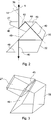
In einer weiter vorteilhaften Ausgestaltung weisen die beiden Prismen jeweils eine erste und eine zweite Seitenfläche sowie eine Basisfläche auf, wobei die erste Seitenfläche zur Basisfläche um den Schnittwinkel, insbesondere um 45°, und die zweite Seitenfläche zur Basisfläche um den halben Schnittwinkel, insbesondere um 22,5°, geneigt ist, wobei die Prismen mit einer ersten Seitenfläche und mit einer Basis zueinander planparallel angeordnet sind. Mit dieser Anordnung wird insgesamt eine verzerrungsfreie Abbildung bzw. Projektion unter Verwendung von lediglich zwei Prismen erzielt, wobei die Basisfläche jeweils sowohl eine Durchtritts- als auch eine Reflexionsfläche darstellt. Ein durch die Basisfläche senkrecht in das jeweilige Prisma eintretender Strahl wird aufgrund der Neigung der zweiten Seitenfläche an dieser total reflektiert und erneut gegen die Basisfläche zurückgeworfen. An dieser wird er nun aufgrund des geänderten Einfallswinkels ebenfalls total reflektiert und rechtwinklig gegen die erste Seitenfläche geworfen, wo er ohne Reflexionsverluste austritt. Gleiches gilt sinngemäß für den umgekehrten Strahlengang. Die erste Seitenfläche und eine Basisfläche bilden die Kopplung zwischen den beiden Prismen, wobei eines der Prismen dem Nickrahmen und das andere Prisma dem Rollrahmen zugeordnet ist. Eine Verdrehung der Prismen gegeneinander durch eine Drehung des Nickrahmens um die Nickachse führt zu keiner Änderung in der optischen Abbildung.In a further advantageous embodiment, the two prisms each have a first and a second side surface and a base surface, wherein the first side surface to the base surface by the cutting angle, in particular by 45 °, and the second side surface to the base surface by half the cutting angle, in particular by 22nd , 5 °, wherein the prisms are arranged with a first side surface and with a base plane-parallel to each other. With this arrangement, a distortion-free imaging or projection is achieved using only two prisms as a whole, wherein the base surface in each case represents both a passage surface and a reflection surface. A ray entering the respective prism perpendicularly through the base surface is totally reflected at the latter due to the inclination of the second side surface and is reflected back against the base surface. At this he is now also totally reflected due to the changed angle of incidence and thrown at right angles against the first side surface, where it emerges without reflection losses. The same applies mutatis mutandis to the reverse beam path. The first side surface and a base surface form the coupling between the two prisms, wherein one of the prisms is associated with the pitch frame and the other prism is associated with the roll frame. A rotation of the prisms against each other by a rotation of the pitch frame about the pitch axis leads to no change in the optical image.
Vorteilhafterweise sind die erste und/oder die zweite Umlenkoptik zur Ausgestaltung eines reellen Zwischenbildes, insbesondere innerhalb der Prismen, ausgebildet. Durch die zweistufige Ausbildung des Strahlengangs insgesamt, wobei ein reelles Zwischenbild zwischen der Objektszene und der Detektions/Sendeeinheit erzeugt wird, wird der Strahlenquerschnitt im Bereich des Zwischenbildes minimiert. Liegt das Zwischenbild innerhalb der Prismen, so können diese, da der Strahlenquerschnitt verringert ist, in ihrer Dimension weiter verringert werden.Advantageously, the first and / or the second deflection optics are designed to form a real intermediate image, in particular within the prisms. Due to the two-stage design of the beam path as a whole, wherein a real intermediate image is generated between the object scene and the detection / transmission unit, the beam cross-section in the region of the intermediate image is minimized. If the intermediate image lies within the prisms, these can be further reduced in their dimension, since the beam cross-section is reduced.
Da die Nickachse gegen die Rollachse um einen Winkel von weniger als 90° geneigt ist, ist es weiter möglich, den Nickrahmen strukturfest anzutreiben. Hierzu ist zweckmäßigerweise ein Verbindungsglied auf dem Nickrahmen angeordnet, in welches zum Antrieb ein strukturfestes, drehbares Koppelglied eingreift. Insbesondere kann das drehbare Koppelglied als ein koaxial zur Rollachse angeordneter Drehkranz, insbesondere als ein Zahnkranz, ausgebildet sein. Mit dieser Ausgestaltung wird es nicht mehr nötig, Zuführleitungen zum Antrieb des Nickrahmens beispielsweise mittels Schleifringen oder dgl. drehbewegbar an den Rollrahmen anzukoppeln. Auf diese Weise entfällt aufwändiger und teuerer Mehraufwand.Since the pitch axis is inclined to the roll axis by an angle of less than 90 °, it is also possible to drive the pitch frame structurally. For this purpose, a connecting member is expediently arranged on the pitch frame, in which engages a structurally fixed, rotatable coupling member for driving. In particular, the rotatable coupling member as a coaxial with the roll axis arranged turntable, in particular as a sprocket, be formed. With this embodiment, it is no longer necessary to couple supply lines for driving the pitch frame, for example by means of slip rings or the like. Rotatably movable to the rolling frame. This eliminates costly and expensive overhead.
Bei der angegebenen Schwenkeinrichtung verläuft die optische Achse durch den Schnittpunkt der Nickachse mit der Rollachse. Aus diesem Grund ist es möglich, die Schwenkeinrichtung unter einer strukturfesten, transparenten Kuppel zu integrieren, deren Zentrum ebenfalls im genannten Schnittpunkt liegt. Dies ermöglicht eine hermetische Abdichtung gegenüber ungünstigen Umweltbedingungen. In the specified pivoting device, the optical axis passes through the intersection of the pitch axis with the roll axis. For this reason, it is possible to integrate the pivoting device under a structurally solid, transparent dome whose center is also located in said intersection. This allows a hermetic seal against adverse environmental conditions.
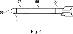
Wie eingangs erwähnt, eignet sich die Schwenkeinrichtung prinzipiell für verschiedenste Anwendungen sowohl im zivilen als auch im wehrtechnischen Bereich. Insbesondere kann die Schwenkeinrichtung in einem Suchkopf eines Lenkflugkörpers integriert sein und der Zielerfassung dienen.As mentioned above, the pivoting device is in principle suitable for a wide variety of applications in both civilian and defense technology. In particular, the pivoting device may be integrated in a seeker head of a guided missile and serve the target detection.
Ausführungsbeispiele der Erfindung werden anhand einer Zeichnung näher erläutert. Dabei zeigen:Embodiments of the invention will be explained in more detail with reference to a drawing. Showing:
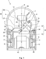
In
Der Rollrahmen
Zum Antrieb des Nickrahmens
Um eine feste Position der Schwenkeinrichtung
Zur Abbildung bzw. zur Projektion einer Objektszene in einem ausgewählten Raumwinkelbereich ist mit dem Nickrahmen
Man erkennt, dass die erste Umlenkoptik
Bei der dargestellten Schwenkeinrichtung
Befindet sich das erste Prisma
Es wird ersichtlich, dass mit der dargestellten optischen Schwenkeinrichtung
Die Detektions-/Sendeeinheit
In
Das zweite Prisma
Zur Bildung des Prismengelenks sind das erste Prisma
Zur Verdeutlichung der optischen Kopplung ist in der dargestellten Drehposition des ersten Prismas
In
BezugszeichenlisteLIST OF REFERENCE NUMBERS
- 11
- SchwenkeinrichtungPivot means
- 33
- Tragstruktursupporting structure
- 44
- Kuppeldome
- 66
- Rollrahmenroll frame
- 77
- NickrahmenNick frame
- 99
- Rollachseroll axis
- 1111
- erstes Lagerfirst camp
- 1212
- Rollantriebroll drive
- 1414
- Nickachsepitch axis
- 1515
- zweites Lagersecond camp
- 1818
- Koppelgliedcoupling member
- 1919
- Verbindungsgliedlink
- 2020
- drittes Lagerthird camp
- 2222
- NickantriebNick drive
- 2424
- Winkelgeber NickAngle encoder Nick
- 2626
- Winkelgeber RollAngle encoder roll
- 2727
- erstes Prismafirst prism
- 2828
- Abbildungsoptikimaging optics
- 3030
- erste Umlenkoptikfirst deflection optics
- 3232
- zweites Prismasecond prism
- 3333
- Fokussieroptikfocusing optics
- 3434
- zweite Umlenkoptiksecond deflection optics
- 3636
- Schnittwinkelcutting angle
- 4040
- Strahlengangbeam path
- 4242
- Detektions-/SendeeinheitDetection / transmission unit
- 4444
- Basisfläche (erstes Prisma)Base area (first prism)
- 4545
- erste Seitenfläche (erstes Prisma)first side surface (first prism)
- 4646
- zweite Seitenfläche (erstes Prisma)second side surface (first prism)
- 4848
- Basisfläche (zweites Prisma)Base area (second prism)
- 4949
- erste Seitenfläche (zweites Prisma)first side surface (second prism)
- 5050
- zweite Seitenfläche (zweites Prisma)second side surface (second prism)
- 5555
- LenkflugkörperMissile
- 5656
- Antriebseinheitdrive unit
- 5757
- Steuereinheitcontrol unit
- 5858
- Suchkopfseeker
Claims (8)
Priority Applications (3)
| Application Number | Priority Date | Filing Date | Title |
|---|---|---|---|
| DE102007035552.3A DE102007035552B4 (en) | 2007-07-28 | 2007-07-28 | Optical pivoting device |
| US12/173,041 US7938542B2 (en) | 2007-07-28 | 2008-07-15 | Optical swiveling device for imaging and/or projection of an object scene |
| EP08013046.1A EP2023179B1 (en) | 2007-07-28 | 2008-07-19 | Optical swivelling device |
Applications Claiming Priority (1)
| Application Number | Priority Date | Filing Date | Title |
|---|---|---|---|
| DE102007035552.3A DE102007035552B4 (en) | 2007-07-28 | 2007-07-28 | Optical pivoting device |
Publications (2)
| Publication Number | Publication Date |
|---|---|
| DE102007035552A1 DE102007035552A1 (en) | 2009-02-05 |
| DE102007035552B4 true DE102007035552B4 (en) | 2016-10-13 |
Family
ID=39731779
Family Applications (1)
| Application Number | Title | Priority Date | Filing Date |
|---|---|---|---|
| DE102007035552.3A Expired - Fee Related DE102007035552B4 (en) | 2007-07-28 | 2007-07-28 | Optical pivoting device |
Country Status (3)
| Country | Link |
|---|---|
| US (1) | US7938542B2 (en) |
| EP (1) | EP2023179B1 (en) |
| DE (1) | DE102007035552B4 (en) |
Families Citing this family (7)
| Publication number | Priority date | Publication date | Assignee | Title |
|---|---|---|---|---|
| DE102011104023B4 (en) * | 2011-06-11 | 2019-07-25 | Diehl Defence Gmbh & Co. Kg | Optical device for a seeker head for a guided missile and seeker head for a guided missile |
| DE102012009172A1 (en) * | 2012-05-08 | 2013-11-14 | Diehl Bgt Defence Gmbh & Co. Kg | Seeker head for a missile |
| AU2015318799B2 (en) * | 2014-09-16 | 2020-11-19 | Li Jun Xia | A fluid dispensing system, a system for processing waste material and a fluid monitoring system |
| DE102015118824B4 (en) * | 2015-11-03 | 2021-08-05 | Sick Ag | Scanning device |
| DE102015118822B4 (en) * | 2015-11-03 | 2021-08-12 | Sick Ag | Scanning device |
| CN110361828B (en) * | 2019-08-22 | 2024-02-09 | 中国工程物理研究院机械制造工艺研究所 | Large-caliber optical element precise adjustment mirror bracket |
| CN111982107B (en) * | 2020-08-27 | 2025-02-11 | 武昌理工学院 | A precision guidance device with self-feedback |
Citations (4)
| Publication number | Priority date | Publication date | Assignee | Title |
|---|---|---|---|---|
| US4061415A (en) * | 1976-07-02 | 1977-12-06 | Sanford Research Institute | Nutating radiation deflecting method and apparatus |
| US4087061A (en) * | 1972-05-08 | 1978-05-02 | The United States Of America As Represented By The Secretary Of The Navy | Wide angle seeker |
| DE3438544C2 (en) * | 1984-10-20 | 1987-12-17 | Bodenseewerk Geraetetechnik Gmbh, 7770 Ueberlingen, De | |
| DE10135222A1 (en) * | 2001-07-24 | 2003-02-06 | Bodenseewerk Geraetetech | Arrangement for detecting object scene has detector, imaging system with object side part pivotable about pitch axis by pitch frame pivotable in roll frame mounted about roll axis |
Family Cites Families (6)
| Publication number | Priority date | Publication date | Assignee | Title |
|---|---|---|---|---|
| DE4135260C1 (en) | 1991-10-25 | 1993-02-25 | Bodenseewerk Geraetetechnik Gmbh, 7770 Ueberlingen, De | |
| DE4443134C2 (en) * | 1994-12-03 | 2001-07-05 | Diehl Stiftung & Co | Sensor device for a missile |
| DE19706958C2 (en) | 1997-02-21 | 2001-11-08 | Lfk Gmbh | Swiveling viewfinder |
| US6064505A (en) * | 1998-11-16 | 2000-05-16 | Eastman Kodak Company | Method and apparatus for movably supporting a reflecting member of a focusing apparatus |
| WO2004066614A1 (en) * | 2003-01-21 | 2004-08-05 | BODENSEEWERK GERäTETECHNIK GMBH | Device for detecting an object scene |
| US7236299B1 (en) | 2006-04-11 | 2007-06-26 | Bae Systems Information And Electronic Systems Integration Inc. | Compact periscopic beam director |
-
2007
- 2007-07-28 DE DE102007035552.3A patent/DE102007035552B4/en not_active Expired - Fee Related
-
2008
- 2008-07-15 US US12/173,041 patent/US7938542B2/en not_active Expired - Fee Related
- 2008-07-19 EP EP08013046.1A patent/EP2023179B1/en not_active Not-in-force
Patent Citations (4)
| Publication number | Priority date | Publication date | Assignee | Title |
|---|---|---|---|---|
| US4087061A (en) * | 1972-05-08 | 1978-05-02 | The United States Of America As Represented By The Secretary Of The Navy | Wide angle seeker |
| US4061415A (en) * | 1976-07-02 | 1977-12-06 | Sanford Research Institute | Nutating radiation deflecting method and apparatus |
| DE3438544C2 (en) * | 1984-10-20 | 1987-12-17 | Bodenseewerk Geraetetechnik Gmbh, 7770 Ueberlingen, De | |
| DE10135222A1 (en) * | 2001-07-24 | 2003-02-06 | Bodenseewerk Geraetetech | Arrangement for detecting object scene has detector, imaging system with object side part pivotable about pitch axis by pitch frame pivotable in roll frame mounted about roll axis |
Also Published As
| Publication number | Publication date |
|---|---|
| US20090027750A1 (en) | 2009-01-29 |
| EP2023179B1 (en) | 2016-05-04 |
| EP2023179A1 (en) | 2009-02-11 |
| US7938542B2 (en) | 2011-05-10 |
| DE102007035552A1 (en) | 2009-02-05 |
Similar Documents
| Publication | Publication Date | Title |
|---|---|---|
| EP2533003B1 (en) | Optical device for guiding radiation of an object scene to a detector | |
| DE102007035552B4 (en) | Optical pivoting device | |
| DE69732878T2 (en) | Image sensor with multiple field of view, which uses only reflective optics | |
| EP2295926B1 (en) | Telescopic sight | |
| DE102012019940A1 (en) | Laser beam directing system and method for aligning optical components of the laser beam directing system | |
| EP2376972B1 (en) | Parallel-sighted, image-reversing prism system | |
| DE10006800A1 (en) | Device for the selection and detection of at least one spectral range of a spectrally fanned light beam | |
| EP2811328A1 (en) | Positioning device, especially for the adjustment of lenses or lens systems in optical devices | |
| EP1586195A1 (en) | Device for detecting an object scene | |
| DE3812174A1 (en) | Combat vehicle dual viewing system | |
| EP2131229A2 (en) | Device with an optical recording system | |
| EP2106561B1 (en) | Multichannel optical rotary joint with high return loss | |
| EP2463692B1 (en) | Prism | |
| DE19904687A1 (en) | Directional telescope arrangement | |
| EP2023182A1 (en) | Prism joint | |
| EP2533004B1 (en) | Optical device | |
| DE19900146A1 (en) | Optical zoom lens system for cameras | |
| EP2774529B1 (en) | Endoscope with image erection device | |
| DE3906701A1 (en) | OUTLOOK ASSEMBLY FOR VEHICLES | |
| DE69805792T2 (en) | Optical architecture for infrared viewing system | |
| EP3835722A1 (en) | Mirroring device | |
| DE102014001151A1 (en) | Measurement of the positions of centers of curvature of optical surfaces of a multi-lens optical system | |
| DE19854489B4 (en) | Wide-angle lens | |
| AT166197B (en) | ||
| DE102007044766B4 (en) | Device for detecting an object scene |
Legal Events
| Date | Code | Title | Description |
|---|---|---|---|
| OP8 | Request for examination as to paragraph 44 patent law | ||
| R018 | Grant decision by examination section/examining division | ||
| R081 | Change of applicant/patentee |
Owner name: DIEHL DEFENCE GMBH & CO. KG, DE Free format text: FORMER OWNER: DIEHL BGT DEFENCE GMBH & CO. KG, 88662 UEBERLINGEN, DE |
|
| R020 | Patent grant now final | ||
| R119 | Application deemed withdrawn, or ip right lapsed, due to non-payment of renewal fee |