DE102004055552B4 - Device for determining and / or monitoring a fill level - Google Patents
Device for determining and / or monitoring a fill level Download PDFInfo
- Publication number
- DE102004055552B4 DE102004055552B4 DE200410055552 DE102004055552A DE102004055552B4 DE 102004055552 B4 DE102004055552 B4 DE 102004055552B4 DE 200410055552 DE200410055552 DE 200410055552 DE 102004055552 A DE102004055552 A DE 102004055552A DE 102004055552 B4 DE102004055552 B4 DE 102004055552B4
- Authority
- DE
- Germany
- Prior art keywords
- unit
- level
- signal
- control unit
- drive
- Prior art date
- Legal status (The legal status is an assumption and is not a legal conclusion. Google has not performed a legal analysis and makes no representation as to the accuracy of the status listed.)
- Expired - Lifetime
Links
- 238000012544 monitoring process Methods 0.000 title claims abstract description 7
- 230000011664 signaling Effects 0.000 claims abstract description 5
- 238000000034 method Methods 0.000 claims abstract description 3
- 239000006260 foam Substances 0.000 claims description 10
- 230000001105 regulatory effect Effects 0.000 abstract description 5
- 230000010355 oscillation Effects 0.000 description 6
- 238000011156 evaluation Methods 0.000 description 5
- 238000005187 foaming Methods 0.000 description 4
- 239000007788 liquid Substances 0.000 description 4
- 230000005284 excitation Effects 0.000 description 3
- 238000001514 detection method Methods 0.000 description 2
- 238000009434 installation Methods 0.000 description 2
- 238000005259 measurement Methods 0.000 description 2
- 230000003534 oscillatory effect Effects 0.000 description 2
- 230000010363 phase shift Effects 0.000 description 2
- 230000007704 transition Effects 0.000 description 2
- 230000001419 dependent effect Effects 0.000 description 1
- 230000000694 effects Effects 0.000 description 1
- 239000012528 membrane Substances 0.000 description 1
- 238000012545 processing Methods 0.000 description 1
Images
Classifications
-
- G—PHYSICS
- G01—MEASURING; TESTING
- G01F—MEASURING VOLUME, VOLUME FLOW, MASS FLOW OR LIQUID LEVEL; METERING BY VOLUME
- G01F23/00—Indicating or measuring liquid level or level of fluent solid material, e.g. indicating in terms of volume or indicating by means of an alarm
- G01F23/22—Indicating or measuring liquid level or level of fluent solid material, e.g. indicating in terms of volume or indicating by means of an alarm by measuring physical variables, other than linear dimensions, pressure or weight, dependent on the level to be measured, e.g. by difference of heat transfer of steam or water
- G01F23/28—Indicating or measuring liquid level or level of fluent solid material, e.g. indicating in terms of volume or indicating by means of an alarm by measuring physical variables, other than linear dimensions, pressure or weight, dependent on the level to be measured, e.g. by difference of heat transfer of steam or water by measuring the variations of parameters of electromagnetic or acoustic waves applied directly to the liquid or fluent solid material
- G01F23/296—Acoustic waves
- G01F23/2966—Acoustic waves making use of acoustical resonance or standing waves
Landscapes
- Physics & Mathematics (AREA)
- Acoustics & Sound (AREA)
- Electromagnetism (AREA)
- Thermal Sciences (AREA)
- Fluid Mechanics (AREA)
- General Physics & Mathematics (AREA)
- Measurement Of Levels Of Liquids Or Fluent Solid Materials (AREA)
Abstract
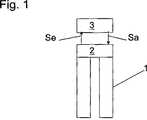
Vorrichtung zur Bestimmung und/oder Überwachung eines vorgegebenen Füllstandes eines Mediums in einem Behälter, mit mindestens einer mechanisch schwingfähigen Einheit (1), mit mindestens einer Antriebs-/Empfangseinheit (2), welche die mechanisch schwingfähige Einheit (1) ausgehend von einem elektrischen Ansteuersignal (Sa) zu Schwingungen anregt, und welche die Schwingungen der mechanisch schwingfähigen Einheit (1) empfängt und in ein elektrisches Empfangssignal (Se) umwandelt, und mit einer Regel-/Steuereinheit (3), welche das elektrische Empfangssignal (Se) von der Antriebs-/Empfangseinheit (2) empfängt und verarbeitet, und welche das elektrische Ansteuersignal (Sa) erzeugt und an die Antriebs-/Empfangseinheit (2) übergibt, wobei die Regel-/Steuereinheit (3) das Ansteuersignal (Sa) derartig erzeugt, dass zwischen dem Empfangssignal (Se) und dem Ansteuersignal (Sa) eine einstellbare Phasendifferenz besteht, und wobei die Regel-/Steuereinheit (3) derartig einstellbar ist, dass sie das Unter- oder das Überschreiten des Füllstandes signalisiert, dadurch gekennzeichnet, dass in Abhängigkeit davon, wie die Regel-/Steuereinheit (3) hinsichtlich der Signalisierung eingestellt ist, ein fester Wert für die Phasendifferenz vorgegeben ist.Device for determining and / or monitoring a given level of a medium in a container, with at least one mechanically oscillatable unit (1), with at least one drive / receiver unit (2), which the mechanically oscillatable unit (1) based on an electrical control signal (Sa) stimulates vibrations, and which receives the vibrations of the mechanically vibratable unit (1) and converts them into an electrical received signal (Se), and with a regulating / control unit (3) which receives the electrical received signal (Se) from the drive - / receiving unit (2) receives and processes, and which generates the electrical control signal (Sa) and transfers it to the drive / receiving unit (2), the regulating / control unit (3) generating the control signal (Sa) in such a way that between the received signal (Se) and the control signal (Sa) there is an adjustable phase difference, and wherein the regulating / control unit (3) is adjustable such that it Signaling falling below or exceeding the filling level, characterized in that a fixed value for the phase difference is specified depending on how the regulating / control unit (3) is set with regard to the signaling.
Description
Die Erfindung bezieht sich auf eine Vorrichtung zur Bestimmung und/oder Überwachung eines vorgegebenen Füllstandes eines Mediums in einem Behälter, mit mindestens einer mechanisch schwingfähigen Einheit, mit mindestens einer Antriebs-/Empfangseinheit, welche die mechanisch schwingfähige Einheit ausgehend von einem elektrischen Ansteuersignal zu Schwingungen anregt, und welche die Schwingungen der mechanisch schwingfähigen Einheit empfängt und in ein elektrisches Empfangssignal umwandelt, und mit einer Regel-/Steuereinheit, welche das elektrische Empfangssignal von der Antriebs-/Empfangseinheit empfängt und verarbeitet, und welche das elektrische Ansteuersignal erzeugt und an die Antriebs-/Empfangseinheit übergibt, wobei die Regel-/Steuereinheit das Ansteuersignal derartig erzeugt, dass zwischen dem Empfangssignal und dem Ansteuersignal eine einstellbare Phasendifferenz besteht, und wobei die Regel-/Steuereinheit derartig einstellbar ist, dass sie aufgrund der Verarbeitung des Empfangssignals mindestens das Unter- oder das Überschreiten des Füllstandes signalisiert. Bei dem Medium handelt es sich beispielsweise um eine Flüssigkeit.The invention relates to a device for determining and / or monitoring a predetermined level of a medium in a container, comprising at least one mechanically oscillatable unit, with at least one drive / receiving unit, which excites the mechanically oscillatable unit from vibrations starting from an electrical drive signal , and which receives the vibrations of the mechanically oscillatable unit and converts them into a received electrical signal, and a control / control unit, which receives and processes the received electrical signal from the drive / receiving unit, and generates the electrical drive signal and to the drive / Receiving unit transfers, wherein the control / control unit generates the drive signal such that between the received signal and the drive signal is an adjustable phase difference, and wherein the control / control unit is adjustable so that they due to the processing of the Receive signal at least the undershooting or exceeding the level signals. The medium is, for example, a liquid.
Von der Anmelderin werden Füllstandsmessgerät der oben beschriebenen Art hergestellt und vertrieben. Das Funktionsprinzip lässt sich beispielsweise der Offenlegungsschrift
Der Erfindung liegt daher die Aufgabe zugrunde, ein Messgerät vorzuschlagen, welches sowohl das Unter-, als auch das Überschreiten eines Füllstandes zuverlässig und unabhängig von Veränderungen des Mediums anzeigt.The invention is therefore based on the object to propose a meter, which displays both the undershooting, as well as the exceeding of a level reliably and independently of changes in the medium.
Die Erfindung löst die Aufgabe dadurch, dass in Abhängigkeit davon, wie die Regel-/Steuereinheit hinsichtlich der Signalisierung eingestellt ist, ein fester Wert für die Phasendifferenz vorgegeben ist. Wie der Offenlegungsschrift
Eine Ausgestaltung der Vorrichtung sieht vor, dass in dem Fall, dass die Regel-/Steuereinheit zur Signalisierung des Unterschreitens des Füllstandes eingestellt ist, ein derartiger Wert für die Phasendifferenz vorgegeben ist, dass die Bestimmung des Füllstandes im Wesentlichen unabhängig von der Viskosität des Mediums ist. Eine wichtige Abhängigkeit der Messungen ist von der Viskosität des Mediums gegeben. Beim Unterschreiten muss jedoch der Übergang von der vollständigen Bedeckung durch das Medium zum freien Zustand angezeigt werden. D. h. eine Viskositätsänderung darf nicht das Schaltsignal auslösen. Daher ist eine Phasendifferenz zu finden, bei welcher die Abhängigkeit von der Viskosität wegfällt.An embodiment of the device provides that in the case that the control / control unit is set to signal the undershooting of the filling level, such a value for the phase difference is predetermined that the determination of the level is substantially independent of the viscosity of the medium , An important dependence of the measurements is given by the viscosity of the medium. When falling below, however, the transition from full coverage through the medium to free state must be indicated. Ie. a viscosity change must not trigger the switching signal. Therefore, a phase difference is found in which the dependence on the viscosity is eliminated.
Eine Ausgestaltung der Vorrichtung beinhaltet, dass in dem Fall, dass die Regel-/Steuereinheit zur Signalisierung des Unterschreitens des Füllstandes eingestellt ist, ein Wert von 70° für die Phasendifferenz vorgegeben ist. Wie der oben genannten Offenlegungsschrift
Eine Ausgestaltung der Vorrichtung sieht vor, dass in dem Fall, dass die Regel-/Steuereinheit zur Signalisierung des Überschreitens des Füllstandes eingestellt ist, ein derartiger Wert für die Phasendifferenz vorgegeben ist, dass die Bestimmung des Füllstandes im Wesentlichen davon unabhängig ist, ob das Medium zumindest teilweise als Schaum vorliegt. Beim Anzeigen des Überschreitens des Füllstandes muss der Übergang vom freien Schwingen zum bedeckten Schwingen erkannt werden. Die Viskositätsabhängigkeit ist somit nicht relevant. Es kann jedoch sein, dass sich Schaum auf dem Medium bildet. Um diesen zu detektieren, ist somit auch eine bestimmte Phasendifferenz erforderlich, die auch eine Detektion des Schaums erlaubt.An embodiment of the device provides that in the case that the control / control unit is set to signal the exceeding of the level, such a value for the phase difference is predetermined that the determination of the level is essentially independent of whether the medium at least partially present as a foam. When exceeding the level, the transition from free swing to covered swing must be recognized. The viscosity dependence is therefore not relevant. However, it may be that foam forms on the medium. To detect this, therefore, a certain phase difference is required, which also allows detection of the foam.
Dabei kann es vorkommen, dass der Schaum erst oberhalb eines bestimmten Dichtewertes detektierbar ist.It may happen that the foam is detectable only above a certain density value.
Eine Ausgestaltung der Vorrichtung beinhaltet, dass in dem Fall, dass die Regel-/Steuereinheit zur Signalisierung des Überschreitens des Füllstandes eingestellt ist, ein Wert zwischen 120° und 140° für die Phasendifferenz vorgegeben ist. Wie den Offenlegungsschriften
Die Erfindung wird anhand der nachfolgenden Zeichnung näher erläutert. Es zeigt:The invention will be explained in more detail with reference to the following drawing. It shows:
In der
BezugszeichenlisteLIST OF REFERENCE NUMBERS
- 11
- Mechanisch schwingfähige EinheitMechanically oscillatable unit
- 22
- Antriebs-/EmpfangseinheitDriver / receiver unit
- 33
- Regel-/SteuereinheitRegulating / control unit
Claims (5)
Priority Applications (1)
| Application Number | Priority Date | Filing Date | Title |
|---|---|---|---|
| DE200410055552 DE102004055552B4 (en) | 2004-11-17 | 2004-11-17 | Device for determining and / or monitoring a fill level |
Applications Claiming Priority (1)
| Application Number | Priority Date | Filing Date | Title |
|---|---|---|---|
| DE200410055552 DE102004055552B4 (en) | 2004-11-17 | 2004-11-17 | Device for determining and / or monitoring a fill level |
Publications (2)
| Publication Number | Publication Date |
|---|---|
| DE102004055552A1 DE102004055552A1 (en) | 2006-05-18 |
| DE102004055552B4 true DE102004055552B4 (en) | 2014-02-13 |
Family
ID=36273902
Family Applications (1)
| Application Number | Title | Priority Date | Filing Date |
|---|---|---|---|
| DE200410055552 Expired - Lifetime DE102004055552B4 (en) | 2004-11-17 | 2004-11-17 | Device for determining and / or monitoring a fill level |
Country Status (1)
| Country | Link |
|---|---|
| DE (1) | DE102004055552B4 (en) |
Families Citing this family (4)
| Publication number | Priority date | Publication date | Assignee | Title |
|---|---|---|---|---|
| DE102007008669A1 (en) | 2007-02-20 | 2008-08-21 | Endress + Hauser Gmbh + Co. Kg | Method for determining and / or monitoring a process variable of a medium and corresponding device |
| FR2921726B1 (en) * | 2007-10-02 | 2010-05-21 | Fr De Services Soc | METHOD AND SYSTEM FOR DETERMINING THE VISCOSITY OF A PRODUCT |
| DE102008054945A1 (en) | 2008-12-19 | 2010-06-24 | Endress + Hauser Gmbh + Co. Kg | Device for determining and / or monitoring a process variable |
| DE102020127077A1 (en) | 2020-10-14 | 2022-04-14 | Endress+Hauser SE+Co. KG | Method of operating a vibronic sensor |
Citations (3)
| Publication number | Priority date | Publication date | Assignee | Title |
|---|---|---|---|---|
| DE4203967C2 (en) * | 1992-02-11 | 1995-06-22 | Endress Hauser Gmbh Co | Device for determining and / or monitoring a predetermined fill level in a container |
| DE10057974A1 (en) * | 2000-11-22 | 2002-05-23 | Endress Hauser Gmbh Co | Determination of liquid level in a container or density of liquid in a container using a vibrating gimbal type body with compensation for temperature, pressure or viscosity variations to improve measurement accuracy |
| DE10302437A1 (en) * | 2003-01-21 | 2004-08-05 | Endress + Hauser Gmbh + Co. Kg | Liquid level monitoring device for monitoring the depth of a medium in a container, e.g. beer, which is liable to form a foam on its surface, whereby the device is able to detect different liquid states, i.e. both foam and liquid |
-
2004
- 2004-11-17 DE DE200410055552 patent/DE102004055552B4/en not_active Expired - Lifetime
Patent Citations (3)
| Publication number | Priority date | Publication date | Assignee | Title |
|---|---|---|---|---|
| DE4203967C2 (en) * | 1992-02-11 | 1995-06-22 | Endress Hauser Gmbh Co | Device for determining and / or monitoring a predetermined fill level in a container |
| DE10057974A1 (en) * | 2000-11-22 | 2002-05-23 | Endress Hauser Gmbh Co | Determination of liquid level in a container or density of liquid in a container using a vibrating gimbal type body with compensation for temperature, pressure or viscosity variations to improve measurement accuracy |
| DE10302437A1 (en) * | 2003-01-21 | 2004-08-05 | Endress + Hauser Gmbh + Co. Kg | Liquid level monitoring device for monitoring the depth of a medium in a container, e.g. beer, which is liable to form a foam on its surface, whereby the device is able to detect different liquid states, i.e. both foam and liquid |
Also Published As
| Publication number | Publication date |
|---|---|
| DE102004055552A1 (en) | 2006-05-18 |
Similar Documents
| Publication | Publication Date | Title |
|---|---|---|
| EP1529202B1 (en) | Device for monitoring a predetermined filling level of a measuring medium in a container | |
| WO2001073383A1 (en) | Method and device for detecting and/or monitoring the level of a medium in a container | |
| EP2054702B1 (en) | Apparatus for determining and/or monitoring a process variable of a medium | |
| EP0875741B1 (en) | Device for determining/monitoring of a predefined liquid level in a container | |
| EP2464951A1 (en) | Multivariable sensor for determining and/or monitoring the fill level and density and/or viscosity of a fluid in a tank | |
| DE102017102550A1 (en) | Condition monitoring of a vibronic sensor | |
| EP1470408B1 (en) | Device for measuring viscosity and/or density | |
| WO2010006896A1 (en) | Device for determining and/or monitoring a process variable and method for testing a device | |
| DE102014118393B4 (en) | Device and method for determining and/or monitoring at least one process variable | |
| DE19720519C2 (en) | Device for determining and / or monitoring a fill level of a medium in a container | |
| DE102006007199A1 (en) | Vibration limit switch arrangement or method for correcting a vibration limit switch switching point | |
| DE102004055552B4 (en) | Device for determining and / or monitoring a fill level | |
| EP0875739B1 (en) | Device for determining and/or monitoring of a predefined liquid level in a container | |
| DE102017111392A1 (en) | Vibronic sensor with noise compensation | |
| EP1800093B1 (en) | Device for determining and/or monitoring a process variable of a medium | |
| EP3881035B1 (en) | Vibronic sensor with temperature compensation | |
| DE102005044725B4 (en) | Membrane oscillator for determining and / or monitoring a process variable of a medium in a container | |
| EP1751507B1 (en) | Device for determining and/or monitoring a process variable of a medium | |
| WO2014146980A1 (en) | Device for determining and/or monitoring a process variable of a medium | |
| EP0875740B1 (en) | Device for determining and/or monitoring of a predefined liquid level in a container | |
| DE102004036359B4 (en) | Method for determining the safety of a liquid level measurement carried out with a vibrating probe in a container | |
| DE102010028161B4 (en) | Method and device for determining and/or monitoring a fill level limit | |
| DE10302437B4 (en) | Device for monitoring a predetermined level of a medium in a container | |
| WO2022078684A1 (en) | Method for operating a vibronic sensor | |
| DE102006058926B4 (en) | Device for determining and / or monitoring a process variable |
Legal Events
| Date | Code | Title | Description |
|---|---|---|---|
| OM8 | Search report available as to paragraph 43 lit. 1 sentence 1 patent law | ||
| R012 | Request for examination validly filed |
Effective date: 20111114 |
|
| R016 | Response to examination communication | ||
| R018 | Grant decision by examination section/examining division | ||
| R020 | Patent grant now final | ||
| R020 | Patent grant now final |
Effective date: 20141114 |
|
| R081 | Change of applicant/patentee |
Owner name: ENDRESS+HAUSER SE+CO. KG, DE Free format text: FORMER OWNER: ENDRESS + HAUSER GMBH + CO. KG, 79689 MAULBURG, DE |
|
| R082 | Change of representative |
Representative=s name: ANDRES, ANGELIKA, DE Representative=s name: ANDRES, ANGELIKA, DIPL.-PHYS., DE |
|
| R082 | Change of representative |
Representative=s name: KOSLOWSKI, CHRISTINE, DR., DE Representative=s name: KOSLOWSKI, CHRISTINE, DIPL.-CHEM. DR. RER. NAT, DE Representative=s name: ANDRES, ANGELIKA, DIPL.-PHYS., DE |
|
| R082 | Change of representative |
Representative=s name: KOSLOWSKI, CHRISTINE, DR., DE Representative=s name: KOSLOWSKI, CHRISTINE, DIPL.-CHEM. DR. RER. NAT, DE |
|
| R071 | Expiry of right |