DE10127552B4 - Method for coupling the switching shaft of a low-voltage circuit breaker with a movable contact carrier - Google Patents
Method for coupling the switching shaft of a low-voltage circuit breaker with a movable contact carrier Download PDFInfo
- Publication number
- DE10127552B4 DE10127552B4 DE2001127552 DE10127552A DE10127552B4 DE 10127552 B4 DE10127552 B4 DE 10127552B4 DE 2001127552 DE2001127552 DE 2001127552 DE 10127552 A DE10127552 A DE 10127552A DE 10127552 B4 DE10127552 B4 DE 10127552B4
- Authority
- DE
- Germany
- Prior art keywords
- coupling
- rocker arm
- contact carrier
- tab
- voltage circuit
- Prior art date
- Legal status (The legal status is an assumption and is not a legal conclusion. Google has not performed a legal analysis and makes no representation as to the accuracy of the status listed.)
- Expired - Fee Related
Links
- 238000010168 coupling process Methods 0.000 title claims abstract description 74
- 230000008878 coupling Effects 0.000 title claims abstract description 73
- 238000005859 coupling reaction Methods 0.000 title claims abstract description 73
- 238000000034 method Methods 0.000 title claims abstract description 11
- 230000014509 gene expression Effects 0.000 claims description 3
- 238000004519 manufacturing process Methods 0.000 description 3
- 238000009434 installation Methods 0.000 description 2
- 238000007493 shaping process Methods 0.000 description 2
- 241001494479 Pecora Species 0.000 description 1
- 230000005540 biological transmission Effects 0.000 description 1
- 239000000969 carrier Substances 0.000 description 1
- 238000005516 engineering process Methods 0.000 description 1
- 238000010791 quenching Methods 0.000 description 1
- 230000000171 quenching effect Effects 0.000 description 1
Classifications
-
- H—ELECTRICITY
- H01—ELECTRIC ELEMENTS
- H01H—ELECTRIC SWITCHES; RELAYS; SELECTORS; EMERGENCY PROTECTIVE DEVICES
- H01H3/00—Mechanisms for operating contacts
- H01H3/32—Driving mechanisms, i.e. for transmitting driving force to the contacts
- H01H3/46—Driving mechanisms, i.e. for transmitting driving force to the contacts using rod or lever linkage, e.g. toggle
-
- H—ELECTRICITY
- H01—ELECTRIC ELEMENTS
- H01H—ELECTRIC SWITCHES; RELAYS; SELECTORS; EMERGENCY PROTECTIVE DEVICES
- H01H69/00—Apparatus or processes for the manufacture of emergency protective devices
Landscapes
- Breakers (AREA)
- Driving Mechanisms And Operating Circuits Of Arc-Extinguishing High-Tension Switches (AREA)
Abstract
Verfahren zur Kopplung der Schaltwelle (11) eines Niederspannungs-Leistungsschalters (1) mit einem bewegbaren Kontaktträger (7) mittels einer Koppelanordnung in Form eines Schaltwellenauslegers (12) und einer Koppellasche (14), wobei an dem Schaltwellenausleger (12) und/oder der Koppellasche (14) Stützelemente (18, 19, 20, 21, 22, 23, 24, 25) vorgesehen sind, dadurch gekennzeichnet, dass mit Hilfe der Stützelemente (18, 19, 20, 21, 22, 23, 24, 25) der Schaltwellenausleger (12) mit der Koppellasche (14) selbsttätig gegenseitig ausgerichtet und anschließend die Koppellasche (14) in den Kontaktträger (7) bei der Montage der beweglichen Strombahn und der Gehäusehälften eingeführt wird.method for coupling the switching shaft (11) of a low-voltage circuit breaker (1) with a movable contact carrier (7) by means of a coupling arrangement in the form of a rocker arm (12) and a coupling lug (14), wherein on the shift shaft arm (12) and / or the coupling tab (14) Supporting elements (18, 19, 20, 21, 22, 23, 24, 25) are provided, characterized that by means of the support elements (18, 19, 20, 21, 22, 23, 24, 25) of the selector shaft boom (12) with the Coupling strap (14) automatically aligned and then the coupling tab (14) in the contact carrier (7) is introduced during assembly of the movable flow path and the housing halves.
Description
Die Erfindung betrifft ein Verfahren zur Koppelung der Schaltwelle eines Niederspannungs-Leistungsschalters mit einem bewegbaren Kontaktträger desselben mittels einer Koppelanordnung in Form eines Schaltwellenausleger und einer Koppellasche.The The invention relates to a method for coupling the switching shaft of a Low-voltage circuit breaker with a movable contact carrier thereof by means of a coupling arrangement in the form of a selector shaft boom and a coupling flap.
Die Ansteuerung des bewegbaren Kontaktträgers bei Niederspannungs-Leistungsschaltern erfolgt herkömmlich im allgemeinen durch eine drehbar gelagerte Schaltwelle, die mittels eines Federspeichers oder sonstigen Schalterantriebs um einen bestimmten Winkel schwenkbar ist. Auf der Schaltwelle ist starr ein Hebelausleger angeordnet und von diesem ausgehende weiterführende, in der Regel als Koppellaschen ausgebildete, Verbindungselemente, die dann die einzelnen Schaltpole oder Kontakte betätigen. Zwischen der Schaltwelle und den Schaltpolen befinden sich also Hebelgelenke, im einfachsten Fall ist das ein Kniehebelgelenk, derartig, dass an einem Schaltpol eine Koppellasche gelenkig befestigt ist, welche über einen Verbindungsbolzen mit einem an der Schaltwelle befindlichen Hebelausleger verbunden ist.The Control of the movable contact carrier in low-voltage circuit breakers takes place conventionally in general by a rotatably mounted switching shaft, which means a spring accumulator or other switch drive to a certain Angle is pivotable. On the stem is rigid a lever arm arranged and outgoing from this continuing, usually as coupling tabs trained, connecting elements, which then the individual switching poles or press contacts. So between the switching shaft and the switching poles are Lever joints, in the simplest case, this is a toggle joint, such, that a coupling tab is hinged at a switching pole, which over a connecting bolt with a located on the shift shaft Lever boom is connected.
Diese Verbindung zwischen der Schaltwelle und dem Kontaktträger muss beim Zusammenbau des Schalters normalerweise so hergestellt werden, dass die am Schaltwellenausleger befestigte Koppellasche oder die sonstigen Koppelglieder in den Kontaktträger eingeführt werden und dort mittels eines Koppelbolzens arretiert werden. Auch für Servicearbeiten ist es notwendig, diese Koppelelemente so zu gestalten, dass der Vorgang des Entkoppelns und Ankoppelns problemlos ohne Spezialwerkzeuge und besondere Schulung ausgeführt werden kann. Es ist nämlich durchaus üblich, derartige Verschleißteile und auch die Kontakte eines Schalters zu ersetzen, und nicht den kompletten Schalter auszutauschen, wenn einige Verschleißteile verbraucht sind.These Connection between the stem and the contact carrier must When assembling the switch normally be made so that attached to the selector shaft boom coupling lobe or other Coupling links in the contact carrier introduced be and locked there by means of a coupling pin. Also for service work It is necessary to make these coupling elements so that the Decoupling and coupling process without any special tools and special training can be. It is quite common, such wear parts and also to replace the contacts of a switch, and not the complete one Replace switch when some wearing parts are used up.
Bei Niederspannungs-Leistungsschaltern mit Kunststoffgehäusen steht aufgrund ihrer kompakten Bauweise im Bereich zwischen der Schaltwelle und dem Schaltpol extrem wenig Manövrierraum für den vorgenannten Arbeitsvorgang zur Verfügung, bei welchem, wie oben dargelegt, die Koppelelemente einseitig mit der Schaltwelle oder aber auch dem Kontaktträger verbunden werden und dann extra ausgerichtet oder mit Spezialwerkzeugen so positioniert werden, dass die Schaltwelle und der bewegbare Kontaktträger einwandfrei miteinander verbunden sind.at Low-voltage circuit breakers with plastic housings stands due to their compact design in the area between the switching shaft and the switching pole extremely little maneuvering space for the said operation available, in which, as above set forth, the coupling elements on one side with the switching shaft or but also the contact carrier be connected and then extra aligned or with special tools be positioned so that the switching shaft and the movable contact carrier properly connected to each other.
In
der
Die
Weiterhin
zeigt die
Aus
der Druckschrift
Dennoch müssen sowohl bei der letztgenannten, als auch bei allen anderen vorgenannten Lösungen die Koppelelemente einseitig mit der Schaltwelle oder aber auch dem Kontaktträger verbunden werden und dann extra ausgerichtet oder mit Spezialwerkzeugen so positioniert werden, dass die Schaltwelle und der bewegbare Kontaktträger einwandfrei miteinander verbunden sind. Alle vorgenannten Lösungen sind darüber hinaus konstruktiv und fertigungstechnisch verhältnismäßig aufwendig und materialintensiv.Yet have to both in the latter, as well as in all other aforementioned solutions the Coupling elements on one side with the switching shaft or else the contact support be connected and then extra aligned or with special tools be positioned so that the switching shaft and the movable contact carrier properly connected to each other. All the above solutions are beyond constructive and manufacturing technology relatively expensive and material-intensive.
Die Aufgabe der vorliegenden Erfindung besteht folglich darin, eine mechanische Verbindung zwischen der Schaltwelle des Schalterantriebs und den bewegbaren Kontaktträgern zu schaf fen, die auf einfache Weise ohne Zuhilfenahme spezieller Werkzeuge herzustellen und wieder zu lösen ist, und bei welcher beim Einbau die zu verbindenden Elemente schon so ausgerichtet sind, dass die Schalterkomponenten nur noch zusammengefügt werden müssen, ohne dass noch eine Positionierung der Teile erfolgen muss, ohne dass diese Ausrichtung den späteren Betriebsablauf behindert, die weiterhin konstruktiv einfach und materialsparend ist und nur einen geringen Fertigungsaufwand erfordert.The object of the present invention is therefore to provide a mechanical connection between the switching shaft of the switch drive and the movable contact carriers to sheep fen, which is easy to manufacture without the aid of special tools and to solve again, and in which the installation elements to be connected already are aligned so that the Schalterkompo nenten need only be joined together without still positioning the parts must be done without this orientation hinders the subsequent operation, which is still structurally simple and material-saving and requires only a low production cost.
Diese Aufgabe wird gemäß der vorliegenden Erfindung durch ein Verfahren mit den Merkmalen des Patentanspruches 1 gelöst, bei dem mit Hilfe der am Schaltwellenausleger und/oder der Koppellasche vorgesehenen Stützelemente der Schaltwellenauslegers mit der Koppellasche selbsttätig gegenseitig ausgerichtet und anschließend die Koppellasche in den Kontaktträger bei der Montage der beweglichen Strombahn und der Gehäusehälften eingeführt wird. Somit erfolgt die Ausrichtung der genannten Koppelelemente derart, dass bei der Montage der beweglichen Strombahn und der Gehäusehälften die Koppellaschen selbsttätig direkt in die Ankoppelöffnungen der Polträger der beweglichen Strombahn eingeführt werden. Es ist also nicht erforderlich, sie mit Hilfe von Spezialwerkzeugen extra auszurichten und zu positionieren.These Problem is in accordance with the present invention solved by a method having the features of claim 1, at with the help of the provided on the selector shaft boom and / or the coupling tab support elements the rocker arm with the coupling tab automatically aligned and subsequently the coupling lug in the contact carrier during assembly of the movable flow path and the housing halves is inserted. Consequently the alignment of said coupling elements takes place such that during assembly of the movable flow path and the housing halves the Coupling lugs automatically directly into the Ankoppelöffnungen the pole carrier introduced the movable current path become. So it is not necessary to use special tools extra to align and position.
Die Stützelemente zur gegenseitigen Ausrichtung können vorteilhaft dadurch gebildet werden, dass die Koppellasche wenigstens eine Anschlagfläche aufweist, die im ausgerichteten Zustand an wenigstens einem am Schaltwellenausleger vorgesehenen Anschlag anliegt. Die Stützelemente zur gegenseitigen Ausrichtung können aber auch dadurch gebildet werden, dass an der Koppellasche wenigstens ein Anschlag vorgesehen ist, mit welchem sie im ausgerichteten Zustand an wenigstens einer Anschlagfläche des Schaltwellenauslegers anliegt.The support elements for mutual alignment advantageously be formed by the fact that the coupling tab at least a stop surface which, in the aligned state on at least one of the control shaft arm provided stop abuts. The support elements for mutual Alignment can but also be formed by the fact that at the coupling tab at least one Stop is provided, with which they in the aligned state on at least one stop surface of the control shaft jib abuts.
Der am Schaltwellenhebel beziehungsweise an der Koppellasche vorgesehene Anschlag ist vorteilhaft als Ausprägung in der Seitenwand des Schaltwellenauslegers beziehungsweise der Koppellasche ausgebildet.Of the provided on the shift shaft lever or on the coupling lug Stop is advantageous as an expression in the side wall of Schaltwellenausleger or the coupling tab formed.
Der Anschlag kann aber auch in Form eines in der Seitenwand des Schaltwellenauslegers beziehungsweise der Koppellasche angeordneten Stiftes vorgesehen werden, welcher zweckmäßig ein in eine Durchgangsbohrung eingepresster Kerbstift oder ein in eine Gewindebohrung eingeschraubter Gewindestift sein kann.Of the But can also stop in the form of a in the side wall of the rocker arm or the coupling tab arranged pin provided which is appropriate one in a through hole pressed groove pin or in a Threaded hole threaded screw can be.
Die Erfindung soll nachfolgend zum besseren Verständnis anhand eines bevorzugten, den Schutzumfang nicht einschränkenden Ausführungsbeispiels näher erläutert werden.The In the following, for the purposes of better understanding, a the scope of protection is not limiting embodiment be explained in more detail.
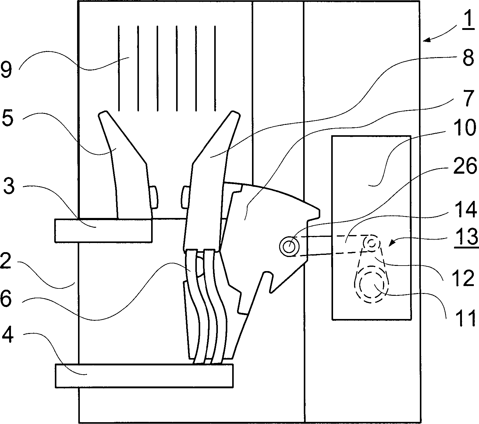
Die
Die
Die
Die
Die
In
der
Die
Auf
der Schaltwelle
Die
Koppelanordnung
Die
Die
Auf
der Schaltwelle
Die
- 11
- Niederspannungs-LeistungsschalterLow-voltage circuit breakers
- 22
- Rückwandrear wall
- 33
- Obere AnschlussschieneUpper connecting rail
- 44
- Untere AnschlussschieneLower connecting rail
- 55
- Fester SchaltkontaktFester switching contact
- 66
- Flexible Verbindungflexible connection
- 77
- Kontaktträgercontact support
- 88th
- Bewegbarer Schaltkontaktmovable switching contact
- 99
- LichtbogenlöschkammerArc chute
- 1010
- Schalterantriebswitch drive
- 1111
- Schaltwelleshift shaft
- 1212
- SchaltwellenauslegerSwitching shaft arm
- 1313
- Koppelanordnungcoupling arrangement
- 1414
- Koppellaschecoupling tab
- 1515
- Hebellever
- 1616
- Hebellever
- 1717
- Gelenkbolzenhinge pins
- 1818
- KerbstiftKerbstift
- 1919
- KerbstiftKerbstift
- 2020
- Anschlagflächestop surface
- 2121
- Anschlagflächestop surface
- 2222
- Ausprägungshaping
- 2323
- Ausprägungshaping
- 2424
- Anschlagflächestop surface
- 2525
- Anschlagflächestop surface
- 2626
- Koppelbolzencoupling bolts
Claims (7)
Priority Applications (1)
| Application Number | Priority Date | Filing Date | Title |
|---|---|---|---|
| DE2001127552 DE10127552B4 (en) | 2001-06-01 | 2001-06-01 | Method for coupling the switching shaft of a low-voltage circuit breaker with a movable contact carrier |
Applications Claiming Priority (1)
| Application Number | Priority Date | Filing Date | Title |
|---|---|---|---|
| DE2001127552 DE10127552B4 (en) | 2001-06-01 | 2001-06-01 | Method for coupling the switching shaft of a low-voltage circuit breaker with a movable contact carrier |
Publications (2)
| Publication Number | Publication Date |
|---|---|
| DE10127552A1 DE10127552A1 (en) | 2002-12-19 |
| DE10127552B4 true DE10127552B4 (en) | 2007-01-04 |
Family
ID=7687440
Family Applications (1)
| Application Number | Title | Priority Date | Filing Date |
|---|---|---|---|
| DE2001127552 Expired - Fee Related DE10127552B4 (en) | 2001-06-01 | 2001-06-01 | Method for coupling the switching shaft of a low-voltage circuit breaker with a movable contact carrier |
Country Status (1)
| Country | Link |
|---|---|
| DE (1) | DE10127552B4 (en) |
Families Citing this family (1)
| Publication number | Priority date | Publication date | Assignee | Title |
|---|---|---|---|---|
| US11984709B2 (en) | 2021-12-01 | 2024-05-14 | Appleton Grp Llc | Actuator for a switch gear of an electric panel |
Citations (6)
| Publication number | Priority date | Publication date | Assignee | Title |
|---|---|---|---|---|
| US3569652A (en) * | 1968-10-24 | 1971-03-09 | Westinghouse Electric Corp | Cam operated circuit breaker with single stroke manual spring charging means |
| FR2589625A1 (en) * | 1985-10-31 | 1987-05-07 | Merlin Gerin | Kinematic chain for transmission beween the control mechanism and the poles of an electric circuit breaker |
| US4679016A (en) * | 1986-01-08 | 1987-07-07 | General Electric Company | Interchangeable mechanism for molded case circuit breaker |
| DE29605081U1 (en) * | 1996-03-08 | 1996-06-05 | Siemens AG, 80333 München | Circuit breaker with isolating contact lever carrier |
| DE19637678A1 (en) * | 1996-09-05 | 1998-03-12 | Siemens Ag | Low voltage circuit breaker with a drive device |
| DE19910172A1 (en) * | 1999-02-24 | 2000-08-31 | Siemens Ag | Power switch with current-limiting opening of switch-contact |
-
2001
- 2001-06-01 DE DE2001127552 patent/DE10127552B4/en not_active Expired - Fee Related
Patent Citations (6)
| Publication number | Priority date | Publication date | Assignee | Title |
|---|---|---|---|---|
| US3569652A (en) * | 1968-10-24 | 1971-03-09 | Westinghouse Electric Corp | Cam operated circuit breaker with single stroke manual spring charging means |
| FR2589625A1 (en) * | 1985-10-31 | 1987-05-07 | Merlin Gerin | Kinematic chain for transmission beween the control mechanism and the poles of an electric circuit breaker |
| US4679016A (en) * | 1986-01-08 | 1987-07-07 | General Electric Company | Interchangeable mechanism for molded case circuit breaker |
| DE29605081U1 (en) * | 1996-03-08 | 1996-06-05 | Siemens AG, 80333 München | Circuit breaker with isolating contact lever carrier |
| DE19637678A1 (en) * | 1996-09-05 | 1998-03-12 | Siemens Ag | Low voltage circuit breaker with a drive device |
| DE19910172A1 (en) * | 1999-02-24 | 2000-08-31 | Siemens Ag | Power switch with current-limiting opening of switch-contact |
Also Published As
| Publication number | Publication date |
|---|---|
| DE10127552A1 (en) | 2002-12-19 |
Similar Documents
| Publication | Publication Date | Title |
|---|---|---|
| EP3011643B1 (en) | Holding frame for plug connector modules | |
| DE102011055977A1 (en) | door actuators | |
| EP1968083B1 (en) | Relay | |
| AT12193U1 (en) | FLAP DRIVE SYSTEM | |
| DE102010023116B4 (en) | Device for switching on and off an electrical switch | |
| EP1284447A1 (en) | Pivotal fitting | |
| EP1856709A1 (en) | Electromechanical switching device | |
| WO2009019175A1 (en) | Coupling arrangement for transmission of the rotational movement of a switching shaft of an electrical switch to at least one position signalling device | |
| DE10127552B4 (en) | Method for coupling the switching shaft of a low-voltage circuit breaker with a movable contact carrier | |
| DE10013160B4 (en) | Switch shaft unit for a switch | |
| EP1196936B1 (en) | Displaceable contact having low electrical resistance | |
| EP1288980B1 (en) | Circuit breaker with a detachable connection between a switching contact and its driving device and method for mounting and demounting the switching contact | |
| DE3802183C2 (en) | ||
| EP1328956B1 (en) | Current limiting low-voltage power circuit breaker | |
| DE102009030608A1 (en) | High-voltage arrangement | |
| EP1851779B1 (en) | Electrical installation switch for a modular construction provided with an interchangeable illumination unit | |
| EP0188482A1 (en) | Switch latch. | |
| EP0454018A2 (en) | Electrical switch gear | |
| DE10137422C1 (en) | Contact carrier for LV switchgear has coupling lever between drive shaft and contact carrier body attached to latter in adjustable position for altering switching force | |
| EP1722383A1 (en) | Driveline for coupling a movable contact to an operating mechanism and low voltage circuit breaker with a driveline | |
| WO2007088003A1 (en) | Multi-pole switching device with an additional housing and a mutual mechanical locking apparatus | |
| WO2001039230A1 (en) | Electrical switchgear comprising several housing parts | |
| DE102004048836A1 (en) | Switching contact arrangement for an electrical switch and electrical switch with a switching contact arrangement | |
| DE1615872C (en) | Electric snap switch for lever operation | |
| DE10013549B4 (en) | Arrangement of a switch |
Legal Events
| Date | Code | Title | Description |
|---|---|---|---|
| OP8 | Request for examination as to paragraph 44 patent law | ||
| 8364 | No opposition during term of opposition | ||
| R119 | Application deemed withdrawn, or ip right lapsed, due to non-payment of renewal fee |