DE10051325B4 - Internal combustion engine - Google Patents
Internal combustion engine Download PDFInfo
- Publication number
- DE10051325B4 DE10051325B4 DE10051325A DE10051325A DE10051325B4 DE 10051325 B4 DE10051325 B4 DE 10051325B4 DE 10051325 A DE10051325 A DE 10051325A DE 10051325 A DE10051325 A DE 10051325A DE 10051325 B4 DE10051325 B4 DE 10051325B4
- Authority
- DE
- Germany
- Prior art keywords
- internal combustion
- combustion engine
- piston
- cylinder
- engine according
- Prior art date
- Legal status (The legal status is an assumption and is not a legal conclusion. Google has not performed a legal analysis and makes no representation as to the accuracy of the status listed.)
- Expired - Fee Related
Links
Classifications
-
- F—MECHANICAL ENGINEERING; LIGHTING; HEATING; WEAPONS; BLASTING
- F02—COMBUSTION ENGINES; HOT-GAS OR COMBUSTION-PRODUCT ENGINE PLANTS
- F02M—SUPPLYING COMBUSTION ENGINES IN GENERAL WITH COMBUSTIBLE MIXTURES OR CONSTITUENTS THEREOF
- F02M23/00—Apparatus for adding secondary air to fuel-air mixture
-
- F—MECHANICAL ENGINEERING; LIGHTING; HEATING; WEAPONS; BLASTING
- F02—COMBUSTION ENGINES; HOT-GAS OR COMBUSTION-PRODUCT ENGINE PLANTS
- F02B—INTERNAL-COMBUSTION PISTON ENGINES; COMBUSTION ENGINES IN GENERAL
- F02B23/00—Other engines characterised by special shape or construction of combustion chambers to improve operation
- F02B23/02—Other engines characterised by special shape or construction of combustion chambers to improve operation with compression ignition
- F02B23/06—Other engines characterised by special shape or construction of combustion chambers to improve operation with compression ignition the combustion space being arranged in working piston
- F02B23/0618—Other engines characterised by special shape or construction of combustion chambers to improve operation with compression ignition the combustion space being arranged in working piston having in-cylinder means to influence the charge motion
- F02B23/0627—Other engines characterised by special shape or construction of combustion chambers to improve operation with compression ignition the combustion space being arranged in working piston having in-cylinder means to influence the charge motion having additional bores or grooves machined into the piston for guiding air or charge flow to the piston bowl
-
- F—MECHANICAL ENGINEERING; LIGHTING; HEATING; WEAPONS; BLASTING
- F02—COMBUSTION ENGINES; HOT-GAS OR COMBUSTION-PRODUCT ENGINE PLANTS
- F02B—INTERNAL-COMBUSTION PISTON ENGINES; COMBUSTION ENGINES IN GENERAL
- F02B23/00—Other engines characterised by special shape or construction of combustion chambers to improve operation
- F02B23/02—Other engines characterised by special shape or construction of combustion chambers to improve operation with compression ignition
- F02B23/06—Other engines characterised by special shape or construction of combustion chambers to improve operation with compression ignition the combustion space being arranged in working piston
- F02B23/0672—Omega-piston bowl, i.e. the combustion space having a central projection pointing towards the cylinder head and the surrounding wall being inclined towards the cylinder center axis
-
- F—MECHANICAL ENGINEERING; LIGHTING; HEATING; WEAPONS; BLASTING
- F02—COMBUSTION ENGINES; HOT-GAS OR COMBUSTION-PRODUCT ENGINE PLANTS
- F02B—INTERNAL-COMBUSTION PISTON ENGINES; COMBUSTION ENGINES IN GENERAL
- F02B31/00—Modifying induction systems for imparting a rotation to the charge in the cylinder
- F02B31/04—Modifying induction systems for imparting a rotation to the charge in the cylinder by means within the induction channel, e.g. deflectors
- F02B31/06—Movable means, e.g. butterfly valves
- F02B31/08—Movable means, e.g. butterfly valves having multiple air inlets, i.e. having main and auxiliary intake passages
-
- F—MECHANICAL ENGINEERING; LIGHTING; HEATING; WEAPONS; BLASTING
- F02—COMBUSTION ENGINES; HOT-GAS OR COMBUSTION-PRODUCT ENGINE PLANTS
- F02M—SUPPLYING COMBUSTION ENGINES IN GENERAL WITH COMBUSTIBLE MIXTURES OR CONSTITUENTS THEREOF
- F02M26/00—Engine-pertinent apparatus for adding exhaust gases to combustion-air, main fuel or fuel-air mixture, e.g. by exhaust gas recirculation [EGR] systems
- F02M26/13—Arrangement or layout of EGR passages, e.g. in relation to specific engine parts or for incorporation of accessories
- F02M26/17—Arrangement or layout of EGR passages, e.g. in relation to specific engine parts or for incorporation of accessories in relation to the intake system
- F02M26/20—Feeding recirculated exhaust gases directly into the combustion chambers or into the intake runners
-
- F—MECHANICAL ENGINEERING; LIGHTING; HEATING; WEAPONS; BLASTING
- F02—COMBUSTION ENGINES; HOT-GAS OR COMBUSTION-PRODUCT ENGINE PLANTS
- F02M—SUPPLYING COMBUSTION ENGINES IN GENERAL WITH COMBUSTIBLE MIXTURES OR CONSTITUENTS THEREOF
- F02M35/00—Combustion-air cleaners, air intakes, intake silencers, or induction systems specially adapted for, or arranged on, internal-combustion engines
- F02M35/10—Air intakes; Induction systems
- F02M35/104—Intake manifolds
- F02M35/108—Intake manifolds with primary and secondary intake passages
-
- F—MECHANICAL ENGINEERING; LIGHTING; HEATING; WEAPONS; BLASTING
- F02—COMBUSTION ENGINES; HOT-GAS OR COMBUSTION-PRODUCT ENGINE PLANTS
- F02B—INTERNAL-COMBUSTION PISTON ENGINES; COMBUSTION ENGINES IN GENERAL
- F02B3/00—Engines characterised by air compression and subsequent fuel addition
- F02B3/06—Engines characterised by air compression and subsequent fuel addition with compression ignition
-
- F—MECHANICAL ENGINEERING; LIGHTING; HEATING; WEAPONS; BLASTING
- F02—COMBUSTION ENGINES; HOT-GAS OR COMBUSTION-PRODUCT ENGINE PLANTS
- F02M—SUPPLYING COMBUSTION ENGINES IN GENERAL WITH COMBUSTIBLE MIXTURES OR CONSTITUENTS THEREOF
- F02M23/00—Apparatus for adding secondary air to fuel-air mixture
- F02M2023/008—Apparatus for adding secondary air to fuel-air mixture by injecting compressed air directly into the combustion chamber
-
- F—MECHANICAL ENGINEERING; LIGHTING; HEATING; WEAPONS; BLASTING
- F02—COMBUSTION ENGINES; HOT-GAS OR COMBUSTION-PRODUCT ENGINE PLANTS
- F02M—SUPPLYING COMBUSTION ENGINES IN GENERAL WITH COMBUSTIBLE MIXTURES OR CONSTITUENTS THEREOF
- F02M26/00—Engine-pertinent apparatus for adding exhaust gases to combustion-air, main fuel or fuel-air mixture, e.g. by exhaust gas recirculation [EGR] systems
- F02M26/02—EGR systems specially adapted for supercharged engines
- F02M26/04—EGR systems specially adapted for supercharged engines with a single turbocharger
- F02M26/05—High pressure loops, i.e. wherein recirculated exhaust gas is taken out from the exhaust system upstream of the turbine and reintroduced into the intake system downstream of the compressor
-
- F—MECHANICAL ENGINEERING; LIGHTING; HEATING; WEAPONS; BLASTING
- F02—COMBUSTION ENGINES; HOT-GAS OR COMBUSTION-PRODUCT ENGINE PLANTS
- F02M—SUPPLYING COMBUSTION ENGINES IN GENERAL WITH COMBUSTIBLE MIXTURES OR CONSTITUENTS THEREOF
- F02M26/00—Engine-pertinent apparatus for adding exhaust gases to combustion-air, main fuel or fuel-air mixture, e.g. by exhaust gas recirculation [EGR] systems
- F02M26/13—Arrangement or layout of EGR passages, e.g. in relation to specific engine parts or for incorporation of accessories
- F02M26/36—Arrangement or layout of EGR passages, e.g. in relation to specific engine parts or for incorporation of accessories with means for adding fluids other than exhaust gas to the recirculation passage; with reformers
-
- F—MECHANICAL ENGINEERING; LIGHTING; HEATING; WEAPONS; BLASTING
- F02—COMBUSTION ENGINES; HOT-GAS OR COMBUSTION-PRODUCT ENGINE PLANTS
- F02M—SUPPLYING COMBUSTION ENGINES IN GENERAL WITH COMBUSTIBLE MIXTURES OR CONSTITUENTS THEREOF
- F02M26/00—Engine-pertinent apparatus for adding exhaust gases to combustion-air, main fuel or fuel-air mixture, e.g. by exhaust gas recirculation [EGR] systems
- F02M26/45—Sensors specially adapted for EGR systems
- F02M26/48—EGR valve position sensors
-
- Y—GENERAL TAGGING OF NEW TECHNOLOGICAL DEVELOPMENTS; GENERAL TAGGING OF CROSS-SECTIONAL TECHNOLOGIES SPANNING OVER SEVERAL SECTIONS OF THE IPC; TECHNICAL SUBJECTS COVERED BY FORMER USPC CROSS-REFERENCE ART COLLECTIONS [XRACs] AND DIGESTS
- Y02—TECHNOLOGIES OR APPLICATIONS FOR MITIGATION OR ADAPTATION AGAINST CLIMATE CHANGE
- Y02T—CLIMATE CHANGE MITIGATION TECHNOLOGIES RELATED TO TRANSPORTATION
- Y02T10/00—Road transport of goods or passengers
- Y02T10/10—Internal combustion engine [ICE] based vehicles
- Y02T10/12—Improving ICE efficiencies
Abstract
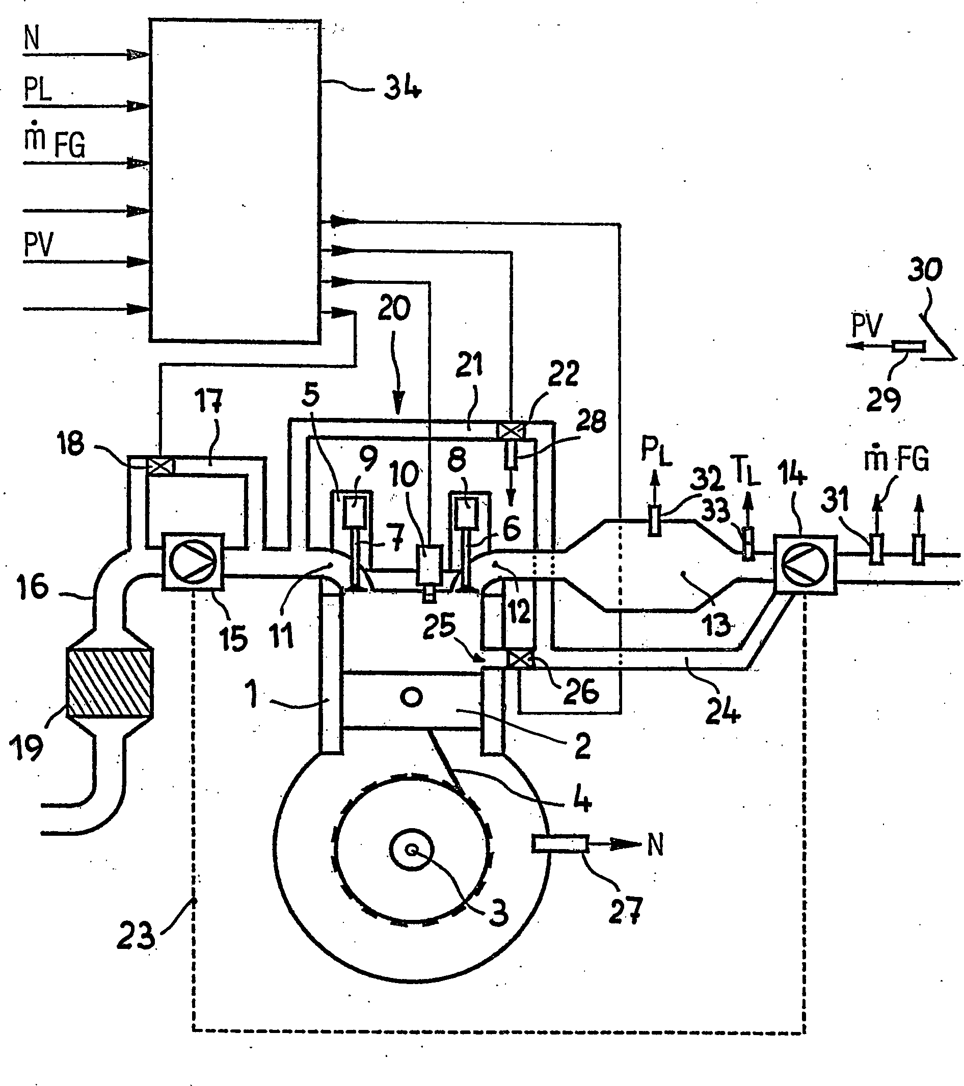
Brennkraftmaschine, insbesondere Dieselbrennkraftmaschine mit zumindest einem Zylinder (1) und einem darin geführten über eine Pleuelstange (4) auf eine Kurbelwelle (3) einwirkenden Kolben (2), einem Zylinderkopf (5) mit durch Ventiltriebe (8, 9) betätigten Gaswechselventilen (6, 7) und mindestens einem Drallkanal (12) zur Zuführung von Ladeluft aus einem Luftzuführsystem, einem Abgassystem, einem im Boden des Kolbens (2) befindlichen Brennraummulde (37) und einer direkt in die Brennraummulde (37) spritzenden Kraftstoffeinspritzdüse sowie mit Mitteln zur Beeinflussung des Ladeluftdralls, dadurch gekennzeichnet, dass in der Wand jedes Zylinders (1) eine oder mehrere Öffnungen (25) eines oder mehrerer tangential in den Zylinder (1) einmündender Kanäle (24) vorgesehen sind, welche sich bei Stellung des Kolbens (2) im unteren Totpunkt über Kanalstücke (35) im Kolben (2) bis zu der im Kolben (2) befindlichen Brennraummulde (37) fortsetzen und während der sonstigen Kolbenbewegung vom Kolben (2) abgedeckt sind und der Kanal bzw. die Kanäle (24) von außen mit einer Druckluftquelle verbunden...Internal combustion engine, in particular diesel engine with at least one cylinder (1) and one about one Connecting rod (4) on a crankshaft (3) acting piston (2), a cylinder head (5) with valve actuators (8, 9) actuated gas exchange valves (6, 7) and at least one swirl channel (12) for the supply of Charge air from an air supply system, an exhaust system, a combustion chamber in the bottom of the piston (2) (37) and a direct injection into the combustion chamber (37) fuel injector and with means for influencing the charge air spin, characterized in that in the wall of each cylinder (1) one or more openings (25) one or more tangentially into the cylinder (1) opening channels (24) are provided, which in position of the piston (2) in bottom dead center over channel sections (35) in the piston (2) to the combustion chamber in the piston (2) (37) continue and during the other piston movement from the piston (2) are covered and the Channel or channels (24) from the outside connected to a compressed air source ...
Description
Die Erfindung betrifft eine Brennkraftmaschine, insbesondere eine Dieselbrennkraftmaschine mit zumindest einem Zylinder und einem darin geführten über eine Pleuelstange auf eine Kurbelwelle einwirkenden Kolben, einem Zylinderkopf mit durch Ventiltriebe betätigten Gaswechselventilen und mindestens einem Drallkanal zur Zuführung von Ladeluft aus einem Luftzuführsystem, einem Abgassystem, einem im Boden des Kolbens befindlichen Brennraum und einer direkt in den Brennraum spritzenden Kraftstoffeinspritzdüse sowie mit Mitteln zur Beeinflussung des Ladeluftdralls.The The invention relates to an internal combustion engine, in particular a diesel internal combustion engine with at least one cylinder and a guided over a connecting rod on a Crankshaft acting piston, a cylinder head with valve trains actuated Gas exchange valves and at least one swirl duct for the supply of Charge air from an air supply system, an exhaust system, a combustion chamber located in the bottom of the piston and a directly injecting into the combustion chamber fuel injector and with means for influencing the charge air swirl.
Mit
Nachteilig dabei ist, dass insbesondere bei geringer Drehzahl der Brennkraftmaschine lediglich eine vergleichsweise geringe Drallintensität erzielt werden kann. Diese geringe Drallintensität verliert beim Verdichtungshub weiter an Energie, so dass bei Einspritzung des Kraftstoffes nicht mehr die für die Kraftstoffverteilung und den Brennverlauf gewünschte Ladungsbewegung vorliegt.adversely It is that, in particular at low speed of the internal combustion engine only a relatively small swirl intensity can be achieved. This low swirl intensity loses energy during the compression stroke, so that when injected the fuel is no longer the fuel distribution and the burning process desired Charge movement is present.
Wie
Bei
Brennkraftmaschinen mit Gleichstromspülung, insbesondere bei Zweitakt-Brennkraftmaschinen,
wie eine solche z. B. mit
Auch
aus der
Bei Brennkraftmaschinen mit ventilgesteuerten Ein- und Auslasskanälen sind solche Einlassschlitze nicht bekannt.at Internal combustion engines with valve-controlled inlet and outlet channels are such inlet slots are not known.
Der Erfindung liegt die Aufgabe zugrunde, eine Brennkraftmaschine gemäß dem Oberbegriff des Patentanspruches 1 so zu verbessern, dass ein von den im Zylinderkopf befindlichen Einlasskanälen, insbesondere einem Drallkanal initiierter Ladungsdrall im Zylinder für den Verdichtungshub in geregelter Weise stabilisiert oder verstärkt werden kann. Of the Invention is based on the object, an internal combustion engine according to the preamble of To claim 1 to improve so that one of the cylinder head located inlet channels, in particular a swirl channel initiated charge twist in the cylinder for the compression stroke can be stabilized or strengthened in a regulated manner.
Die Erfindung löst diese Aufgabe mit den kennzeichnenden Merkmalen des Patentanspruches 1. Die Unteransprüche haben vorteilhafte Weiterbildungen der Erfindung zum Gegenstand.The Invention solves This object with the characterizing features of claim 1. The dependent claims have advantageous developments of the invention the subject.
Der nach dem Ansaugtakt im unteren Totpunkt kurzzeitig verharrende Kolben gibt eine oder mehrere Öffnungen eines Kanals frei, über den durch eine Druckluftquelle ein Luftstrom tangential in den Zylinderraum gebracht wird. Dieser Luftstrom kann in Abhängigkeit von Motorparametern wie Z. B. Drehzahl, Last, Kraftstoffqualität, Außenluftdruck und dergleichen durch eine elektronische Steuereinheit sowie ein Regelventil zumessbar sein.Of the after the intake stroke at bottom dead center briefly persistent piston gives one or more openings a channel, over through a compressed air source, an air flow tangentially into the cylinder chamber is brought. This airflow may be dependent on engine parameters such as speed, load, fuel quality, outside air pressure, and the like by an electronic control unit and a control valve zumessbar be.
Die durch die Öffnungen in der Zylinderwand einströmende Luft verstärkt den Drall der Ladung im Zylinder. Der Querschnitt der Öffnungen kann dafür relativ klein gehalten sein. Insbesondere für direkteinspritzende Dieselmotoren wird es vorteilhaft sein, wenn sich an die Öffnungen in der Zylinderwand ein Kanal im Kolben zu dem im Kolbenboden befindlichen Brennraum fortsetzt und dort tangential austritt. Damit gelingt es, gezielt den Drall in der Kolbenmulde zu unterstützen.The through the openings flowing in the cylinder wall Air amplified the spin of the charge in the cylinder. The cross section of the openings can be relative for that be kept small. Especially for direct injection diesel engines it will be advantageous if the openings in the cylinder wall a channel in the piston to the combustion chamber located in the piston head continue and exit there tangentially. This succeeds, purposefully to support the twist in the piston recess.
Bei Brennkraftmaschinen mit einem Ladegebläse bietet es sich an, als Druckluftquelle das Ladegebläse zu nutzen. Dabei kann dieses Ladegebläse auch der Verdichter eines Abgasturboladers sein.at Internal combustion engines with a charge blower, it makes sense, as a compressed air source the charging fan to use. This charger can also be the compressor of a Be exhaust gas turbocharger.
Die Druckluftquelle kann jedoch auch von einer Luftpumpe bzw. einem Gebläse gebildet sein, welches ent weder direkt von der Brennkraftmaschine angetrieben ist oder einen separaten Antrieb, z. B. durch einen Elektromotor aufweist. The However, compressed air source can also by an air pump or a fan be formed, which ent neither driven directly by the internal combustion engine is or a separate drive, z. B. by an electric motor having.
Eine solche Luftpumpe kann z. B. kombiniert werden mit einer ohnehin vorhandenen Zusatzluftpumpe für die während der Katalysatoraufheizzeit erfolgende Zumischung von Luft zum Abgas.A Such air pump can, for. B. be combined with an anyway existing additional air pump for the while the Katalysatoraufheizzeit taking place mixing of air to the exhaust gas.
Es kann aber auch zweckmäßig sein, für die Bereitstellung der Druckluft eine gesonderte elektrisch angetriebene Pumpe vorzusehen. Als Vorteil elektrisch angetriebener Pumpen ist die relativ einfache Regelung der Pumpleistung über die Drehzahl zu sehen.It but it can also be useful for the provision the compressed air to provide a separate electrically driven pump. As an advantage of electrically driven pumps is relatively simple Control of pump power over to see the speed.
Über den tangential in den Zylinder einmündenden Kanal kann der Zylinderladung auch Abgas zugeführt werden, wenn sich zur Beeinflussung des Abgasverhaltens der Brennkraftmaschine eine Abgasrückführung erforderlich macht. Das Abgas kann der im Kanal geführten Luft beigemischt werden. Die Beimischungsrate ist dabei frei wählbar zwischen 0 und 100 %. Als ein besonderer Vorteil ergibt sich dadurch, dass die im rückgeführten Abgas mitgeführten Partikel die Ansaugwege im Zylinderkopf nicht verschmutzen können.On the tangentially opening into the cylinder Channel can also be supplied to the cylinder charge exhaust, if to influence the exhaust behavior of the internal combustion engine exhaust gas recirculation required power. The exhaust gas can be added to the air guided in the channel. The admixture rate is freely selectable between 0 and 100%. As a particular advantage results from the fact that in the recirculated exhaust entrained particles can not pollute the intake passages in the cylinder head.
Ausführungsbeispiele der Erfindung sind nachstehend anhand einer Zeichnung näher beschrieben. Es zeigenembodiments The invention are described below with reference to a drawing. Show it
Die
Brennkraftmaschine nach
Im
Zylinderkopf
Dem
Drallkanal
Der
Verdichter
In
der Brennkraftmaschine sind Sensoren zum Erfassen der Betriebsparameter
vorgesehen, z. B. ein Drehzahlsensor
Die
Sensoren geben Signale zu einer elektronischen Steuereinheit
In
Claims (8)
Priority Applications (1)
| Application Number | Priority Date | Filing Date | Title |
|---|---|---|---|
| DE10051325A DE10051325B4 (en) | 2000-10-17 | 2000-10-17 | Internal combustion engine |
Applications Claiming Priority (1)
| Application Number | Priority Date | Filing Date | Title |
|---|---|---|---|
| DE10051325A DE10051325B4 (en) | 2000-10-17 | 2000-10-17 | Internal combustion engine |
Publications (2)
| Publication Number | Publication Date |
|---|---|
| DE10051325A1 DE10051325A1 (en) | 2002-04-18 |
| DE10051325B4 true DE10051325B4 (en) | 2006-06-08 |
Family
ID=7660024
Family Applications (1)
| Application Number | Title | Priority Date | Filing Date |
|---|---|---|---|
| DE10051325A Expired - Fee Related DE10051325B4 (en) | 2000-10-17 | 2000-10-17 | Internal combustion engine |
Country Status (1)
| Country | Link |
|---|---|
| DE (1) | DE10051325B4 (en) |
Cited By (1)
| Publication number | Priority date | Publication date | Assignee | Title |
|---|---|---|---|---|
| DE102009056223A1 (en) | 2009-11-28 | 2011-06-01 | Audi Ag | Internal combustion engine has cylinder, whose cylinder wall limits combustion chamber together with piston and cylinder head, where piston is movable in cylinder |
Families Citing this family (3)
| Publication number | Priority date | Publication date | Assignee | Title |
|---|---|---|---|---|
| FR2896273A1 (en) * | 2006-01-18 | 2007-07-20 | Renault Sas | High-pressure gas injector for internal combustion engine has gas jet activator operated during second half of compression cycle |
| DE102017206616A1 (en) * | 2017-04-20 | 2018-10-25 | Bayerische Motoren Werke Aktiengesellschaft | Method for operating an internal combustion engine, and internal combustion engine |
| RU2727952C1 (en) * | 2019-12-09 | 2020-07-27 | Андрей Сергеевич Космодамианский | Internal combustion engine |
Citations (7)
| Publication number | Priority date | Publication date | Assignee | Title |
|---|---|---|---|---|
| DE3126250A1 (en) * | 1981-07-03 | 1983-01-20 | Audi Nsu Auto Union Ag, 7107 Neckarsulm | Injection internal combustion engine, especially diesel internal combustion engine |
| DE3642455A1 (en) * | 1985-12-23 | 1987-07-02 | Christian Bartsch | Internal combustion engine operating on the two-stroke principle |
| EP0204687B1 (en) * | 1985-06-07 | 1990-09-12 | AVL Gesellschaft für Verbrennungskraftmaschinen und Messtechnik mbH.Prof.Dr.Dr.h.c. Hans List | Two-stroke internal-combustion engine |
| DE4338645A1 (en) * | 1993-11-12 | 1995-05-18 | Harald Armbruster | IC engine with inlet and outlet valves and cylinder wall slide valve |
| DE19621635A1 (en) * | 1996-05-30 | 1997-12-04 | Audi Ag | Diesel IC-engine cylinder head |
| DE19827250A1 (en) * | 1998-06-18 | 1998-11-12 | Herbert Dipl Ing Kern | Two-stroke internal combustion engine with one or more cylinders |
| DE19755689A1 (en) * | 1997-12-16 | 1999-06-24 | Blodig Guenter Priv Doz Dr Ing | Swirl adjusting device for IC engines |
-
2000
- 2000-10-17 DE DE10051325A patent/DE10051325B4/en not_active Expired - Fee Related
Patent Citations (7)
| Publication number | Priority date | Publication date | Assignee | Title |
|---|---|---|---|---|
| DE3126250A1 (en) * | 1981-07-03 | 1983-01-20 | Audi Nsu Auto Union Ag, 7107 Neckarsulm | Injection internal combustion engine, especially diesel internal combustion engine |
| EP0204687B1 (en) * | 1985-06-07 | 1990-09-12 | AVL Gesellschaft für Verbrennungskraftmaschinen und Messtechnik mbH.Prof.Dr.Dr.h.c. Hans List | Two-stroke internal-combustion engine |
| DE3642455A1 (en) * | 1985-12-23 | 1987-07-02 | Christian Bartsch | Internal combustion engine operating on the two-stroke principle |
| DE4338645A1 (en) * | 1993-11-12 | 1995-05-18 | Harald Armbruster | IC engine with inlet and outlet valves and cylinder wall slide valve |
| DE19621635A1 (en) * | 1996-05-30 | 1997-12-04 | Audi Ag | Diesel IC-engine cylinder head |
| DE19755689A1 (en) * | 1997-12-16 | 1999-06-24 | Blodig Guenter Priv Doz Dr Ing | Swirl adjusting device for IC engines |
| DE19827250A1 (en) * | 1998-06-18 | 1998-11-12 | Herbert Dipl Ing Kern | Two-stroke internal combustion engine with one or more cylinders |
Non-Patent Citations (4)
| Title |
|---|
| 08334027 AA |
| JP Patent Abstracts of Japan: 08177495 AA |
| Patent Abstracts of Japan & JP 08177495 A * |
| Patent Abstracts of Japan & JP 08334027 A * |
Cited By (1)
| Publication number | Priority date | Publication date | Assignee | Title |
|---|---|---|---|---|
| DE102009056223A1 (en) | 2009-11-28 | 2011-06-01 | Audi Ag | Internal combustion engine has cylinder, whose cylinder wall limits combustion chamber together with piston and cylinder head, where piston is movable in cylinder |
Also Published As
| Publication number | Publication date |
|---|---|
| DE10051325A1 (en) | 2002-04-18 |
Similar Documents
| Publication | Publication Date | Title |
|---|---|---|
| DE19616555C2 (en) | Diesel engine | |
| DE102004032589B4 (en) | Internal combustion engine with exhaust gas aftertreatment and method for its operation | |
| DE102010021449B4 (en) | Method for operating an internal combustion engine and internal combustion engine | |
| EP1413727A1 (en) | Method for shutdown of an internal combustion engine and internal combustion engine to carry out this method | |
| DE10224719B4 (en) | Apparatus and method for feeding cylinders of supercharged internal combustion engines | |
| DE102005001757A1 (en) | Internal combustion engine with a cylinder associated with the gas pressure vessel and method for operating the internal combustion engine | |
| DE10329019A1 (en) | Internal combustion engine with a compressor in the intake system and method for this purpose | |
| WO2019149542A1 (en) | Spark-ignition internal combustion engine having urea introduction device and method for operating an internal combustion engine of this type | |
| DE10051325B4 (en) | Internal combustion engine | |
| DE102015214107A1 (en) | Internal combustion engine with a compressor and an additional compressor | |
| EP1956210B1 (en) | Method for operating a longitudinally wound two stroke diesel engine and a longitudinally wound two-stroke diesel motor | |
| DE102018003476A1 (en) | Internal combustion engine and method for its operation | |
| EP1067281B1 (en) | Spark ignited reciprocating piston engine | |
| EP1777388A1 (en) | Two-stroke engine | |
| DE19906463C1 (en) | Supercharged internal combustion motor with an exhaust feedback has an additional outlet valve at the control valves for the cylinders to set the exhaust feedback for the most effective motor running | |
| DE102007053891B4 (en) | Method for operating an internal combustion engine with auto-ignition | |
| DE19947784B4 (en) | Method for starting an internal combustion engine | |
| EP3591186B1 (en) | Method for operating a combustion engine with a trim adjuster assigned to the compressor | |
| DE102019203698B4 (en) | Air control device for an engine and method therefor | |
| EP3452704A1 (en) | Two-stroke internal combustion engine | |
| DE4036537C1 (en) | IC engine toxics reduction system - involves mixing off-gas from previous cycle to fresh air content | |
| EP2161427B1 (en) | Method for operating a longitudinally scavenged two-stroke large diesel engine | |
| DE19903579A1 (en) | Pressure charged internal combustion engine has means of blowing compressed air from pressure source into air compressor section of pressure charger or into upstream air suction passage opening out into it | |
| DE102010037649B4 (en) | System for conducting charge air and exhaust gas to an internal combustion engine, method for operating such a system and internal combustion engine with such a system | |
| DE112013007493B4 (en) | Internal combustion engine for a hybrid drive system and such a drive system |
Legal Events
| Date | Code | Title | Description |
|---|---|---|---|
| OM8 | Search report available as to paragraph 43 lit. 1 sentence 1 patent law | ||
| 8110 | Request for examination paragraph 44 | ||
| 8364 | No opposition during term of opposition | ||
| 8327 | Change in the person/name/address of the patent owner |
Owner name: GM GLOBAL TECHNOLOGY OPERATIONS, INC., DETROIT, US |
|
| 8328 | Change in the person/name/address of the agent |
Representative=s name: STRAUSS, P., DIPL.-PHYS.UNIV. MA, PAT.-ANW., 65193 |
|
| 8380 | Miscellaneous part iii |
Free format text: PFANDRECHT |
|
| 8380 | Miscellaneous part iii |
Free format text: PFANDRECHT AUFGEHOBEN |
|
| 8380 | Miscellaneous part iii |
Free format text: PFANDRECHT |
|
| 8327 | Change in the person/name/address of the patent owner |
Owner name: GM GLOBAL TECHNOLOGY OPERATIONS LLC , ( N. D. , US |
|
| R081 | Change of applicant/patentee |
Owner name: GM GLOBAL TECHNOLOGY OPERATIONS LLC (N. D. GES, US Free format text: FORMER OWNER: GM GLOBAL TECHNOLOGY OPERATIONS, INC., DETROIT, MICH., US Effective date: 20110323 |
|
| R119 | Application deemed withdrawn, or ip right lapsed, due to non-payment of renewal fee |
Effective date: 20140501 |