CN86101459A - The improvement of self-energising disc brakes - Google Patents
The improvement of self-energising disc brakes Download PDFInfo
- Publication number
- CN86101459A CN86101459A CN198686101459A CN86101459A CN86101459A CN 86101459 A CN86101459 A CN 86101459A CN 198686101459 A CN198686101459 A CN 198686101459A CN 86101459 A CN86101459 A CN 86101459A CN 86101459 A CN86101459 A CN 86101459A
- Authority
- CN
- China
- Prior art keywords
- break
- angle
- plate
- action
- boss
- Prior art date
- Legal status (The legal status is an assumption and is not a legal conclusion. Google has not performed a legal analysis and makes no representation as to the accuracy of the status listed.)
- Pending
Links
Images

Classifications
-
- F—MECHANICAL ENGINEERING; LIGHTING; HEATING; WEAPONS; BLASTING
- F16—ENGINEERING ELEMENTS AND UNITS; GENERAL MEASURES FOR PRODUCING AND MAINTAINING EFFECTIVE FUNCTIONING OF MACHINES OR INSTALLATIONS; THERMAL INSULATION IN GENERAL
- F16D—COUPLINGS FOR TRANSMITTING ROTATION; CLUTCHES; BRAKES
- F16D55/00—Brakes with substantially-radial braking surfaces pressed together in axial direction, e.g. disc brakes
- F16D55/02—Brakes with substantially-radial braking surfaces pressed together in axial direction, e.g. disc brakes with axially-movable discs or pads pressed against axially-located rotating members
- F16D55/04—Brakes with substantially-radial braking surfaces pressed together in axial direction, e.g. disc brakes with axially-movable discs or pads pressed against axially-located rotating members by moving discs or pads away from one another against radial walls of drums or cylinders
- F16D55/14—Brakes with substantially-radial braking surfaces pressed together in axial direction, e.g. disc brakes with axially-movable discs or pads pressed against axially-located rotating members by moving discs or pads away from one another against radial walls of drums or cylinders with self-tightening action, e.g. by means of coacting helical surfaces or balls and inclined surfaces
-
- F—MECHANICAL ENGINEERING; LIGHTING; HEATING; WEAPONS; BLASTING
- F16—ENGINEERING ELEMENTS AND UNITS; GENERAL MEASURES FOR PRODUCING AND MAINTAINING EFFECTIVE FUNCTIONING OF MACHINES OR INSTALLATIONS; THERMAL INSULATION IN GENERAL
- F16D—COUPLINGS FOR TRANSMITTING ROTATION; CLUTCHES; BRAKES
- F16D2125/00—Components of actuators
- F16D2125/18—Mechanical mechanisms
- F16D2125/20—Mechanical mechanisms converting rotation to linear movement or vice versa
- F16D2125/34—Mechanical mechanisms converting rotation to linear movement or vice versa acting in the direction of the axis of rotation
- F16D2125/36—Helical cams, Ball-rotating ramps
-
- F—MECHANICAL ENGINEERING; LIGHTING; HEATING; WEAPONS; BLASTING
- F16—ENGINEERING ELEMENTS AND UNITS; GENERAL MEASURES FOR PRODUCING AND MAINTAINING EFFECTIVE FUNCTIONING OF MACHINES OR INSTALLATIONS; THERMAL INSULATION IN GENERAL
- F16D—COUPLINGS FOR TRANSMITTING ROTATION; CLUTCHES; BRAKES
- F16D2125/00—Components of actuators
- F16D2125/18—Mechanical mechanisms
- F16D2125/58—Mechanical mechanisms transmitting linear movement
- F16D2125/66—Wedges
Landscapes
- Engineering & Computer Science (AREA)
- General Engineering & Computer Science (AREA)
- Mechanical Engineering (AREA)
- Braking Arrangements (AREA)
Abstract
A kind of expanding self-energising disc brakes adopts one to place the hydraulic actuator in the brake casing to carry out general service brake.Actuator comprises an oil hydraulic cylinder, and a hole is arranged on the cylinder, pair of pistons in the hole, move and the heel pressure plate on boss contact, the line of action of force that piston is added on the projection is positioned on the parallel plane Transverse plane plane at angle with each plate place.This can be reached at angle by the surface of contact of center line that makes the hole or boss.The tilt angle theta e of actuator can be with settling the formed inclined-plane of groove edge of ball to adapt on the plate.
Description
The present invention relates to a kind of self-energising disc brakes, it adopts the rotating friction disk that has the friction material pad, and by being positioned in the middle of the friction disk, by the pressure plate of the protruding seat of fixed guide centering be located at the pressure plate adjacent surface on work in coordination and the groove of reversed dip in ball or roller realize contacting of braking surface that interval in the same housing is relative, angled in the opposite direction rotation pressure plate during brake operating, because ball or roller will move upward along the inclined-plane of groove edge, just make the separated from each other and pressing friction dish of pressure plate that it is contacted with braking surface, pressure plate continues the boss of pressing friction dish on a plate and has propped up a stop-motion seat on the housing, and the angled rotation of the continuation of another piece pressure plate provides a boosting function.
Above-mentioned automatic force-boosting break can be dry type or liquid-cooling type, and this break has been widely used in tractor or other vehicle.Below just be referred to as aforesaid break.
Being operating as of known aforementioned break adopts hydraulic pressure to carry out normal service brake.In a kind of known structure, pressure plate places the hydraulic actuator drive in the housing to do angled reciprocal rotation by one, this hydraulic actuator comprises a hydraulic cylinder, it has an axial hole, the axis in hole is tangent with plate, a pair of reverse piston is arranged in the hole, and its outer end acts between the boss on the plate.In this known structure, the axis in hole is positioned on the landscape surface with each pressure plate place plane parallel.Like this, the overwhelming majority that applies breaking force onboard acts on the described in-plane.
According to the present invention, in aforesaid automatic force-boosting break, general service brake is carried out the hydraulic operation braking by a hydraulic actuator, this hydraulic actuator acts in housing and between the boss on the pressure plate, hydraulic pressure device comprises a hydraulic cylinder, it has an axial bore, there is the same adjacent boss of at least one piston to act on mutually in the hole, the axis in hole is tangent with plate, the line of action that piston puts on the boss on the plate with a landscape surface of each pressure plate place plane parallel at angle.
Line of action of force helps the use and the stability of break at angle, because breaking force with a radial component effect onboard.
When line of action of force with the direction of axially separating that helps plate at angle the time, the inclination on the size of this angle or the number of degrees and the formed inclined-plane of groove edge adapts, improved efficient thus, because thrust acts directly on the moving direction of plate, may need the permissible error of guide ledges is controlled in the very low range to guarantee the enough stability of break in this case.For this reason, may need to carry out extra machining.
When line of action of force is positioned at one when impelling the mutually axially close direction of plate, the protruding seat that lead adopts common permissible error can reach stable and does not need extra machining.
The braking action line of action of force can be reached by the described plane that the axis that makes axial bore is positioned at angle at angle, or reaches at angle by the approximal surface that makes on the boss with piston acts on mutually.
Hydraulic cylinder can be fixed on the housing, acts between the boss in the through hole of the piston of a pair of counteragent on cylinder body.
In this structure, cylinder body can be connected on the mounting plate, or makes one with mounting plate, and mounting plate removably is fixed on the housing and covers on the housing one and allows cylinder body stretch in the housing radially opening.
This is convenient and simplified structure only removes plural clamping bolt because actuator can take out and replace and gets final product from break.
Can also be on mounting plate and actuator affix in order to stop and the mechanical braking mechanism of hand brake in emergency circumstances.
Even if mechanical mechanism is so added up, it also can stretch into housing from one second radial opening on the housing, and second radial opening is provided with first radial opening at interval with an angle.
Yet, had better stretch in the break by a common radial opening with hydraulic actuator at the mechanical mechanism of this outside effect.This helps to utilize existing production line processing, and there is more selection the position that feasible input power is applied on the break.
Some embodiments of the present invention can be referring to accompanying drawing, wherein:
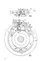
Fig. 1 is the end elevation of an expanding brake part;
Fig. 2 is the section along 2-2 line among Fig. 1;
Fig. 3 is the section along 3-3 line among Fig. 1;
Fig. 4 is the view of similar Fig. 1 of another break embodiment;
Fig. 5 is the section along 5-5 line among Fig. 4;
Fig. 6 is the view of similar Fig. 2 among the another embodiment;
Fig. 7 is the view of similar Fig. 2 among another embodiment.
Shown in the accompanying drawing 1-3 is a kind of common expanding brake, wherein have friction pad on two rotating friction disks 1,2, and link to each other with the spline the same axis, friction disk depended on pressure plate 5,6 realize the contact of the radially braking surface that interval in the same housing 4 is relative, and pressure plate is between friction disk, and by the fixed guide seat 7 of three angled placements, 8,9 centerings, ball 10 be positioned at work in coordination on two adjacent surfaces of pressure plate 5,6 and the groove 3 of reversed dip in.
A radial opening 20 on the flange plate 17 is used for installing a hydraulic actuator 22, and by this actuator 22, break can adopt hydraulic pressure to operate.
As shown in the figure, hydraulic actuator 22 has an oil hydraulic cylinder 24, and the axial hole of a both ends open is arranged on the cylinder, has the piston 26,27 of a pair of counteragent to act on boss 28,29 on the plate 5,6 in the hole.A pressure area that forms between piston 26 and 27 liang of adjacent the inners links to each other by passage 32 same brake master cylinders, and an oil expulsion channel 33 also links to each other with the pressure area.
Oil hydraulic cylinder 24 is connected into one with the inner that is suspended at a contiguous block 34 on the mounting plate 35.Mounting plate 35 has covered opening 20, and is fixed on the flange plate 17 at spaced apart bolt 36 on the circumference with at least two.
The longitudinal center line 37 in hole is tangent with plate 5,6, and is positioned at one with becoming a θ with the Transverse plane of plate 5,6 place plane parallel
eOn the plane of angle.Angle θ
eTiltangle with the plane of inclination 11 of each groove
rRelevant.
If the angle of inclination of the axis in hole 37 is θ
e, vertical action is " e ", and bevel angle θ
rAnd radius is " r ", has so:
θ
e=tan
-1(tanθ
r×r)/(e)
When break carries out hydraulic braking by hydraulic main cylinder, piston 26 with 27 with the motion of opposite direction and promote two boss 28 and 29 it is separated with the generation braking action.Because the axis 37 of oil hydraulic cylinder 24 has an angle of inclination, piston 26 and 27 active force make pressure plate 5,6 do radial and axial motion simultaneously.
When break adopts hand brake, act on braking force on the lever 43 and make the rotate rotational of untie-sell 42 of lever, thereby with radial direction pulling wedge-shaped blocks 47 and make described action piece ball separately.Because ball 10 is with the cooperation of groove 3, plate 5 and 6 just rotates to produce aforesaid braking action in the opposite direction.
The effective length of bar 48 can be adjusted wearing and tearing with the friction compensation pad by the position of adjusting nut 50,51.
In the break of Fig. 4 and Fig. 5, mechanical braking operating mechanism 40 stretches in the break from radial opening 20.In this structure, braking maneuver mechanism 40 comprises a bell crank lever 60, and it links to each other with plate 5 with a roll pin 64.Toggle-action lever 60 has the flange of a part-circular to act on mutually from the boss 29 of axially crossing plate 5 with one on the plate 6.Toggle-action lever 60 drives the untie-sell that rotates by a pull bar 61 and rotates, and the same again lever 62 in the outer end of pull bar 61 connects mutually.One end of lever 62 is contained on the mounting plate 35 one rotationally and rotates on the coupling 63.Therefore, when braking force was applied to the other end of lever, it just outwards spurred pull bar 61, also just drove bell crank lever 60 rotations simultaneously and did rotation separated from each other to promote two plates 5,6.
Bell crank lever parallels to the axis 37, i.e. also θ at angle
eTherefore, be added in plate 5 and active force on 6 and have with hydraulic actuator 22 similar direction and form.Roll pin 64 has the bar of a taper, and it is contained in the circular port on the both arms curved bar handle bar 60 so that bar 60 location, and in pin 64 tapped holes that are screwed on the plate 6, this tapped hole vertically is beneficial to processing with the plane at plate place.
Other structure of Fig. 4 and break shown in Figure 5 is described identical with Fig. 1 to Fig. 3 with action, and corresponding reference signs also refers to corresponding part.
In above-described embodiment, such a case may appear, make pressure plate 5 and the 6 braking force components that produce the direction of axially separating also can make plate 5,6 much bigger in the amount of separating at the position relative with the diametric(al) of actuator 22 at the separately amount ratio of actuator 22 regions.Because this effect, act near the power on the ball of actuator 22 and reduced, the ball 10 that is arranged in the relative position of diametric(al) of actuator 22 has then played a point action at braking process, and pressure plate 5,6 is relatively lifted to actuator 22.As a result, the rotation arm of force is far away more from zero angle, and the amount of raising is also big more.
In order to remedy this effect, lead protruding seat 7 and 8 and pressure plate 5 and 6 between EE Error Excepted should to be chosen as to be zero in the deviation of assemble on same protruding 7 and 8 the surface of contact of back pressure plate 5 and 6.In order to reach required EE Error Excepted, guide surface may also need machining.
In another structure shown in the accompanying drawing 6, boss 28 and 29 reverse arrangement, boss is positioned at circumferential one-tenth one spacing and position relative to each other, and each boss 28,29 also extends through the periphery of another piece plate with total axial direction.Vertical substantially with the acting surface 70,71 on piston 26 and the 27 interactional boss 28,29 with the center line 37 in the hole of oil hydraulic cylinder 24.
During the break action, piston 26,27 acts on the axial component of the braking force on the boss 28,29 with such directive effect, and it makes stressed in groove 3 near the ball 10 of actuator 22 at least.
Fulcrum is transferred to ball 10 near actuator 22 from being positioned at the ball 10 at the relative position of diametric(al) of actuator 22.Even if at actuator 22 with corresponding to an angle still occurs between any fulcrum on the ball 10, it is relative with 6 possibility little to lift plate 5.Compare with embodiment shown in Figure 5 with Fig. 1 to Fig. 3 and Fig. 4 and to be about 1/3rd, raise basic disappearance relatively between the plate 5 and 6.Existing EE Error Excepted between protruding seat 7,8 and the plate 5,6 just still can keep, and no longer needs to carry out machining to reach the zero error between plate 5,6 and the boss surface of contact.
Other structure of break shown in Figure 6 is described identical with Fig. 5 with Fig. 1 to Fig. 3 and Fig. 4 with action, and corresponding reference signs also refers to corresponding part.
In the structure of the another break embodiment shown in the accompanying drawing 7, the center line in the hole of oil hydraulic cylinder 24 37 is with the plane parallel at plate place, and each boss 28 and 29 surface of contact 70,71 vertical lines parallel to each other and the concentricity line 37 that tilts become a θ
eThe angle.
Like this, the same with Fig. 6 embodiment, the ball 10 near actuator 22 is stressed in groove 3 at least during braking, has just produced the same effect with Fig. 6 mechanism.
Claims (11)
1, a kind of self-energising disc brakes, employing has the rotating friction disk (1 of friction material pad, 2), and by being positioned in the middle of the friction disk, by the protruding seat (7 of fixed guide, 8,9) pressure plate (5 of centering, 6) with on being positioned at the pressure plate adjacent surface work in coordination and the contacting of braking surface that the ball of the groove (3) of reversed dip or interval that roller (10) is realized same housing (4) are relative, during brake operating with opposite direction rotation pressure plate, because ball or roller will move upward along the inclined-plane (11) of groove edge, just make the separated from each other and pressing friction dish of pressure plate that it is contacted with braking surface, pressure plate continues the boss (5a of pressing friction dish on a plate, 6a) propped up the stop-motion seat (9) on the housing, being rotated further of another piece pressure plate provides a boosting function, be characterised in that: break is with the hydraulic operation of a hydraulic actuator (22) when carrying out general service brake, actuator (22) is positioned at housing (4) and the boss on pressure plate (28,29) effect between, this actuator comprises a hydraulic cylinder (24), one axial bore is arranged on the cylinder body, at least one piston (26 is arranged in the hole, 27) with an adjacent boss effect, the same plate (5 of the center line in hole, 6) tangent, the line of action of force that piston is applied to boss with a Transverse plane that is parallel to each plane, plate place at angle.
2, according to a kind of break of claim 1, it is characterized in that line of action of force at angle with the direction that helps plate (5,6) and axially separate, the size of this angle adapts with the inclined degree on inclined-plane (11).
3, according to a kind of break of claim 2, it is characterized in that:
θ
e=tan
-1(tanθr×r)/(e)
Wherein: θ
eIt is the angle of inclination of line of action of force when vertical action is " e ";
θ
rIt is the angle of when radius is " r " inclined-plane (11).
4,, it is characterized by line of action of force and be tending towards impelling the axially close mutually direction of plate (5,6) at angle with one according to a kind of break of claim 1.
5,, it is characterized in that the braking action line of action of force is reached by the described plane that the center line that makes axial bore (37) is positioned at angle at angle according to a kind of break of the arbitrary claim in front.
6,, it is characterized in that the braking action line of action of force is reached at angle by the surface of contact that the same piston (26,27) that makes boss (28,29) acts on mutually at angle according to a kind of break of arbitrary of claim 1 to 4.
7,, it is characterized in that piston (26,27) same boss (28,29) in the through hole of hydraulic cylinder (24) of a pair of counteragent acts on mutually according to a kind of break of the arbitrary claim in front.
8, according to a kind of break of the arbitrary claim in front, it is characterized in that cylinder body (24) is attached on the mounting plate (35), mounting plate removably is fixed on housing (4) and goes up and cover on the housing one and allow cylinder body (24) stretch into radial opening (20) in the housing.
9,, it is characterized in that going up with mechanical braking operating mechanism (40) at mounting plate (35) and hydraulic actuator (22) according to a kind of break of the arbitrary claim in front.
10, according to a kind of break of claim 9, it is characterized in that mechanical braking operating mechanism (40) stretches in the housing from one second opening (52), the opening (20) that the same cylinder body of second opening (52) (24) stretches in the break is arranged with an angle intervals.
11,, it is characterized in that being used for mechanical braking and handle machinery (40) and go up parts (61) of handling and stretch into the interior opening (20) of break by cylinder body (24) and stretch in the break according to a kind of break of claim 9.
Applications Claiming Priority (4)
| Application Number | Priority Date | Filing Date | Title |
|---|---|---|---|
| GB858506163A GB8506163D0 (en) | 1985-03-09 | 1985-03-09 | Self-energising disc brakes |
| GB8506163 | 1985-03-09 | ||
| GB8524855 | 1985-10-09 | ||
| GB858524855A GB8524855D0 (en) | 1985-03-09 | 1985-10-09 | Self-energising disc brakes |
Publications (1)
| Publication Number | Publication Date |
|---|---|
| CN86101459A true CN86101459A (en) | 1986-11-26 |
Family
ID=26288954
Family Applications (1)
| Application Number | Title | Priority Date | Filing Date |
|---|---|---|---|
| CN198686101459A Pending CN86101459A (en) | 1985-03-09 | 1986-03-08 | The improvement of self-energising disc brakes |
Country Status (5)
| Country | Link |
|---|---|
| EP (1) | EP0195533B1 (en) |
| CN (1) | CN86101459A (en) |
| BR (1) | BR8601006A (en) |
| DE (1) | DE3662809D1 (en) |
| ES (1) | ES8701931A1 (en) |
Cited By (2)
| Publication number | Priority date | Publication date | Assignee | Title |
|---|---|---|---|---|
| CN100509558C (en) * | 2005-11-30 | 2009-07-08 | 梅西耶-布加蒂公司 | Electromechanical brake with angular displaceable actuators |
| CN102444681A (en) * | 2010-09-30 | 2012-05-09 | 日立汽车系统株式会社 | Thrust generating apparatus, disk brake and stabilizer |
Families Citing this family (2)
| Publication number | Priority date | Publication date | Assignee | Title |
|---|---|---|---|---|
| GB8604717D0 (en) * | 1986-02-26 | 1986-04-03 | Lucas Ind Plc | Self-energising disc brakes |
| IN172739B (en) * | 1987-07-22 | 1993-11-13 | Lucas Ind Plc |
Family Cites Families (6)
| Publication number | Priority date | Publication date | Assignee | Title |
|---|---|---|---|---|
| US2955681A (en) * | 1954-01-13 | 1960-10-11 | Bendix Corp | Disk brake |
| US3343632A (en) * | 1965-07-12 | 1967-09-26 | Lambert & Brake Corp | Self-adjusting disc brake |
| DE2640304A1 (en) * | 1976-09-08 | 1978-03-09 | Kloeckner Humboldt Deutz Ag | Mechanically operated vehicle disc brake - has axially spreadable disc pair turned in opposite directions by lever and link mechanism |
| GB2014261A (en) * | 1978-02-11 | 1979-08-22 | Girling Ltd | Disc Brakes for Vehicles |
| US4383593A (en) * | 1980-05-09 | 1983-05-17 | Lucas Industries Limited | Hydraulically and mechanically operable disc brakes |
| US4549636A (en) * | 1982-11-06 | 1985-10-29 | Lucas Industries Public Limited Company | Disc brakes for vehicles |
-
1986
- 1986-02-24 EP EP86301291A patent/EP0195533B1/en not_active Expired
- 1986-02-24 DE DE8686301291T patent/DE3662809D1/en not_active Expired
- 1986-03-07 BR BR8601006A patent/BR8601006A/en not_active IP Right Cessation
- 1986-03-07 ES ES552785A patent/ES8701931A1/en not_active Expired
- 1986-03-08 CN CN198686101459A patent/CN86101459A/en active Pending
Cited By (3)
| Publication number | Priority date | Publication date | Assignee | Title |
|---|---|---|---|---|
| CN100509558C (en) * | 2005-11-30 | 2009-07-08 | 梅西耶-布加蒂公司 | Electromechanical brake with angular displaceable actuators |
| CN102444681A (en) * | 2010-09-30 | 2012-05-09 | 日立汽车系统株式会社 | Thrust generating apparatus, disk brake and stabilizer |
| CN102444681B (en) * | 2010-09-30 | 2015-11-18 | 日立汽车系统株式会社 | Thrust generating apparatus, disk type braker and stabilizer |
Also Published As
| Publication number | Publication date |
|---|---|
| EP0195533B1 (en) | 1989-04-12 |
| BR8601006A (en) | 1986-11-18 |
| DE3662809D1 (en) | 1989-05-18 |
| ES552785A0 (en) | 1986-12-01 |
| ES8701931A1 (en) | 1986-12-01 |
| EP0195533A1 (en) | 1986-09-24 |
Similar Documents
| Publication | Publication Date | Title |
|---|---|---|
| CA1060357A (en) | Disc brake | |
| SE440689B (en) | DISC BRAKE | |
| AU659227B2 (en) | Wet disc brake | |
| KR0158897B1 (en) | Disc brake for vehicles, especially road vehicles | |
| US3999635A (en) | Disc brake caliper and lining carrier supporting means | |
| CN1015567B (en) | Dual disc brake | |
| JP2000018291A (en) | Radial mount type disc brake | |
| KR100471910B1 (en) | Multiple disk brake system with integrated parking brake | |
| CN1052057C (en) | Improved S-cam for drum brake | |
| CN86101459A (en) | The improvement of self-energising disc brakes | |
| CN1010758B (en) | Arrangement for regulation of rotating condition and reversing of printing machine | |
| EP0131496A1 (en) | Multi-disc brake | |
| US4327924A (en) | Seal for elevator drive mechanism | |
| CN86101461A (en) | The improvement of self-energising disc brakes | |
| KR20030038683A (en) | Wet brake system | |
| GB2045356A (en) | Rotary positivedisplacement fluid-machines | |
| CN1512090A (en) | Pressure container with quick action opening and closing mechanism | |
| JPH0574728B2 (en) | ||
| JPH08219296A (en) | Slip ring type seal device | |
| CN1454298A (en) | Brake plate | |
| CN116753252B (en) | Automobile drum brake, braking method and automobile | |
| CN1094658A (en) | Centrifugal rotor with a web that combines | |
| JP2001132612A (en) | Liquid-operated hub driving device | |
| CN113944706B (en) | Five-tooth linkage type brake of integrated calipers for commercial vehicle and braking method of five-tooth linkage type brake | |
| CN1235216A (en) | Brake assembly of washing machine |
Legal Events
| Date | Code | Title | Description |
|---|---|---|---|
| C06 | Publication | ||
| PB01 | Publication | ||
| WD01 | Invention patent application deemed withdrawn after publication |