CN2866049Y - Drawer type die - Google Patents
Drawer type die Download PDFInfo
- Publication number
- CN2866049Y CN2866049Y CN 200520121361 CN200520121361U CN2866049Y CN 2866049 Y CN2866049 Y CN 2866049Y CN 200520121361 CN200520121361 CN 200520121361 CN 200520121361 U CN200520121361 U CN 200520121361U CN 2866049 Y CN2866049 Y CN 2866049Y
- Authority
- CN
- China
- Prior art keywords
- mold
- die
- positioner
- guide
- bed die
- Prior art date
- Legal status (The legal status is an assumption and is not a legal conclusion. Google has not performed a legal analysis and makes no representation as to the accuracy of the status listed.)
- Expired - Lifetime
Links
Images


Landscapes
- Perforating, Stamping-Out Or Severing By Means Other Than Cutting (AREA)
Abstract
The utility model discloses a drawer type mold, which is characterized by simple structure, lower cost, quick installation, easy debugging and high-precision locating. Concretely, it is comprised of lower die (1) and upper die (2). The lower die (1) includes lower pedestal (3), guide pole (7) on the lower pedestal (3), lower mold (4) and a pair of guide rail (9) vertically set on the lower pedestal (3). In addition, the upper die (2) involves upper pedestal (5), guide hole (8) and upper mold (6) set on the upper pedestal (5) and a pair of guide rail (9) vertically set on the upper pedestal (5). Guide hole (8) matches guide pole (7). Lower mold (4) and upper mold (6) slide along the guide rail (9). The utility model is applicable to die cutting of circuit board.
Description
Technical field
The utility model relates to a kind of drawer type mould, especially relates to a kind of die-cut mould of circuit board that is used for.
Background technology
The die-cut technology that is applied to circuit board at present is a lot, has laser cutting, the cutting of gong bed and machinery die-cut.Laser cutting cost height wherein, cutting speed is slow, is not suitable for large-scale production; The cutting of gong bed is fit to the die-cut of a spot of plate, utilizes this method just not need the die sinking tool, but is unsuitable for large-scale sharp processing; Machinery is die-cut can die-cut according to our needs in advance shape fabricating mould, and then install, die-cut, be die-cut mode routine, general that is used for the circuit board punch extermal form.But mechanical general mould when die-cut is installed and is needed manual location mostly, and the adjustment time is longer, and the machining accuracy of manual location is also lower.So prior art has the following disadvantages: cost height, installation are slowly, debugging is complicated, positioning accuracy is low.
The utility model content
Technical problem to be solved in the utility model is to overcome the deficiencies in the prior art, and a kind of simple in structure, cost is low, installation is fast, debugging is simple and positioning accuracy is high drawer type mould is provided.
The technical scheme that the utility model adopted is: the utility model comprises counterdie and patrix, described counterdie comprises bottom base, is arranged at guide pillar and bed die and a pair of guide rail that vertically is arranged on the described bottom base on the described bottom base, described patrix comprises top base, is arranged at guide hole and mold and a pair of guide rail that vertically is arranged at described top base on the described top base, described guide hole and described guide pillar are suitable, and described bed die and described mold can slide along described guide rail respectively.
Described counterdie and described patrix also comprise a pair of positioner respectively; described positioner is arranged at described bottom base and described top base the inside respectively; described positioner is provided with some alignment pins moving up and down; be respectively arranged with the locating hole that is complementary with described alignment pin on described bed die and the described mold; described positioner is provided with the screw rod that stretches out described bottom base and described top base, and described screw rod is provided with positioning knob.
Be respectively equipped with handle on described bed die and the described mold.
The beneficial effects of the utility model are: because the utility model has adopted guide rail, can be along the mould and the positioner of guide rail slip, form the mould structure of drawer type, select according to wiring board to be processed when using first, bed die also pushes mould in the guide rail, fix with alignment pin, go up then, down, a left side, the right punch press workbench of regulating, make guide pillar and guide hole can correcting on, counterdie is a upright position, on, the interlock degree of depth of counterdie enables neat cutting, just first plate can have been done, to be designed to same thickness at the described mold and the bed die of every kind of circuit board, when reusing like this, only need to replace with according to different wiring boards, bed die, and do not need to regulate again, therefore install fast, debugging is simple and positioning accuracy is high, and the utility model is relatively simple for structure, cost is low.
Description of drawings
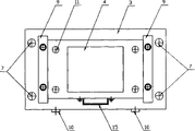
Fig. 1 is the structural representation of the utility model counterdie 1;
Fig. 2 is the plan structure schematic diagram of the utility model counterdie 1;
Fig. 3 is the structural representation of the utility model patrix 2;
Fig. 4 is the structural representation of looking up of the utility model patrix 2;
Fig. 5 is the structural representation of positioner 10 of the present utility model.
The specific embodiment
As Fig. 1, Fig. 2, Fig. 3, Fig. 4, shown in Figure 5, the utility model comprises counterdie 1, patrix 2.Described counterdie 1 comprises bottom base 3 and is arranged at guide pillar 7 and bed die 4 and pair of guide rails 9 and a pair of positioner 10 on the described bottom base 3; Described patrix 2 comprises top base 5 and is arranged at guide hole 8 and bed die 6 and pair of guide rails 9 and a pair of positioner 10 on the described top base 5; Described guide hole 8 and a pair of sliding pair of described guide pillar 7 suitable formation, described bottom base 3 is fixed on the punch press workbench, described top base 5 is fixed on the drift of punch press, pair of guide rails 9 is vertically fixed on the described bottom base 3 and is in the two ends, the left and right sides of described bed die 4 respectively, pair of guide rails 9 is vertically fixed on the described top base 5 and the two ends, the left and right sides of the described mold 6 that is in respectively, and described bed die 4 and described mold 6 can slide along described guide rail 9 respectively.
A pair of described positioner 10 on the counterdie 1 is arranged at described bottom base 3 the insides respectively, each longitudinal positioning device 10 is provided with two alignment pins 12 moving up and down, and the corresponding position is provided with the locating hole 11 that is complementary with described alignment pin 12 on the bed die 4 of bottom base 3 tops; Similar therewith, a pair of described positioner 10 on the patrix 2 is arranged at described top base 5 the insides respectively, each positioner 10 is provided with two alignment pins 12 moving up and down, and the corresponding position is provided with the locating hole 11 that is complementary with described alignment pin 12 on the mold 6 of top base 5 tops; Described positioner 10 is provided with the screw rod 13 that stretches out described bottom base 3 and described top base 5, and described screw rod 13 is provided with positioning knob 14.
Be respectively equipped with handle 15 on described bed die 4 and the described mold 6.
When installing first, respectively bottom base 3 is fixed on the punch press workbench, top base 5 is fixed on the drift of punch press, the described handle 15 of Hand held mould pushes mould in the described guide rail 9 then, rotate the positioning knob 14 on the described positioner 10, alignment pin is inserted in the locating hole with fixed mould, left and right adjusting make guide pillar 7 and guide hole 8 can the upper and lower mould of correcting a upright position, the interlock degree of depth of the upper and lower mould of upper and lower adjusting enables neat cutting, and it is die-cut and checked just can to begin to do initial workpiece then.In addition, can also hand described handle 15 carrying moulds, use faster convenience.To be designed to same thickness at the mold 6 and the bed die 4 of every kind of circuit board, in the time of will making different circuit boards like this, only need at different circuit boards replace with, bed die gets final product, and do not need to adjust punch press, so the utility model is a kind of simple in structure, cost is low, installation is fast, debugging is simple and positioning accuracy is high drawer type mould.
Claims (3)
1, a kind of drawer type mould, comprise counterdie (1), patrix (2), described counterdie (1) comprises bottom base (3) and is arranged at guide pillar (7) and bed die (4) on the described bottom base (3), described patrix (2) comprises top base (5) and is arranged at guide hole (8) and mold (6) on the described top base (5), described guide hole (8) is suitable with described guide pillar (7), it is characterized in that: described counterdie (1) and described patrix (2) also comprise a pair of guide rail (9) that vertically is arranged at described bottom base (3) and vertically is arranged at described top base (5) respectively, and described bed die (4) and described mold (6) can slide along described guide rail (9) respectively.
2, drawer type mould according to claim 1, it is characterized in that: described counterdie (1) and described patrix (2) also comprise a pair of positioner (10) respectively, described positioner (10) is arranged at described bottom base (3) and described top base (5) the inside respectively, described positioner (10) is provided with some alignment pins moving up and down (12), be respectively arranged with the locating hole (11) that is complementary with described alignment pin (12) on described bed die (4) and the described mold (6), described positioner (10) is provided with the screw rod (13) that stretches out described bottom base (3) and described top base (5), and described screw rod (13) is provided with positioning knob (14).
3, drawer type mould according to claim 1 and 2 is characterized in that: be respectively equipped with handle (15) on described bed die (4) and the described mold (6).
Priority Applications (1)
| Application Number | Priority Date | Filing Date | Title |
|---|---|---|---|
| CN 200520121361 CN2866049Y (en) | 2005-12-30 | 2005-12-30 | Drawer type die |
Applications Claiming Priority (1)
| Application Number | Priority Date | Filing Date | Title |
|---|---|---|---|
| CN 200520121361 CN2866049Y (en) | 2005-12-30 | 2005-12-30 | Drawer type die |
Publications (1)
| Publication Number | Publication Date |
|---|---|
| CN2866049Y true CN2866049Y (en) | 2007-02-07 |
Family
ID=37701752
Family Applications (1)
| Application Number | Title | Priority Date | Filing Date |
|---|---|---|---|
| CN 200520121361 Expired - Lifetime CN2866049Y (en) | 2005-12-30 | 2005-12-30 | Drawer type die |
Country Status (1)
| Country | Link |
|---|---|
| CN (1) | CN2866049Y (en) |
Cited By (8)
| Publication number | Priority date | Publication date | Assignee | Title |
|---|---|---|---|---|
| CN100382661C (en) * | 2005-12-30 | 2008-04-16 | 珠海元盛电子科技股份有限公司 | Drawer type mould |
| CN102335931A (en) * | 2011-07-22 | 2012-02-01 | 苏州天加新材料有限公司 | Die cutting mechanism of bag making machine |
| CN102672758A (en) * | 2012-05-10 | 2012-09-19 | 苏州市飞莱克斯电路电子有限公司 | Matching structure of combined mold and punching machine for manufacturing flexible circuit board |
| CN103796431A (en) * | 2012-11-02 | 2014-05-14 | 富葵精密组件(深圳)有限公司 | Line folding mould |
| CN104338815A (en) * | 2014-10-11 | 2015-02-11 | 陈菊芳 | Large punch press applied to automobile processing and provided with movable base |
| CN104552451A (en) * | 2015-01-04 | 2015-04-29 | 京东方科技集团股份有限公司 | Cutting device |
| CN110788931A (en) * | 2019-12-05 | 2020-02-14 | 惠州市华阳多媒体电子有限公司 | Punching die |
| CN112643790A (en) * | 2020-11-09 | 2021-04-13 | 龙南骏亚柔性智能科技有限公司 | Novel install drawer type soft or hard combined plate forming die fast |
-
2005
- 2005-12-30 CN CN 200520121361 patent/CN2866049Y/en not_active Expired - Lifetime
Cited By (10)
| Publication number | Priority date | Publication date | Assignee | Title |
|---|---|---|---|---|
| CN100382661C (en) * | 2005-12-30 | 2008-04-16 | 珠海元盛电子科技股份有限公司 | Drawer type mould |
| CN102335931A (en) * | 2011-07-22 | 2012-02-01 | 苏州天加新材料有限公司 | Die cutting mechanism of bag making machine |
| CN102672758A (en) * | 2012-05-10 | 2012-09-19 | 苏州市飞莱克斯电路电子有限公司 | Matching structure of combined mold and punching machine for manufacturing flexible circuit board |
| CN103796431A (en) * | 2012-11-02 | 2014-05-14 | 富葵精密组件(深圳)有限公司 | Line folding mould |
| CN103796431B (en) * | 2012-11-02 | 2017-03-01 | 富葵精密组件(深圳)有限公司 | Broken line mould |
| CN104338815A (en) * | 2014-10-11 | 2015-02-11 | 陈菊芳 | Large punch press applied to automobile processing and provided with movable base |
| CN104552451A (en) * | 2015-01-04 | 2015-04-29 | 京东方科技集团股份有限公司 | Cutting device |
| CN110788931A (en) * | 2019-12-05 | 2020-02-14 | 惠州市华阳多媒体电子有限公司 | Punching die |
| CN110788931B (en) * | 2019-12-05 | 2023-10-20 | 惠州市华阳智能技术有限公司 | Punching die |
| CN112643790A (en) * | 2020-11-09 | 2021-04-13 | 龙南骏亚柔性智能科技有限公司 | Novel install drawer type soft or hard combined plate forming die fast |
Similar Documents
| Publication | Publication Date | Title |
|---|---|---|
| CN2866049Y (en) | Drawer type die | |
| CN101570071B (en) | Automatic punching machine | |
| CN200974142Y (en) | Double end footwear mould carving and milling machine | |
| CN102189288A (en) | Numerical control double-station mould engraving and milling machine | |
| CN201128010Y (en) | Aiming type automatic piercing machine for decoration | |
| CN203126324U (en) | Vertical type numerical control engraving machine | |
| CN206926447U (en) | One kind automation glass engraving machine | |
| CN100382661C (en) | Drawer type mould | |
| CN204182755U (en) | A kind of automatic punching machine | |
| CN101700669B (en) | Mouse profiling machine | |
| CN207577174U (en) | Bender positioning tool | |
| CN204195883U (en) | A kind of automatic punching machine | |
| CN1931487A (en) | Machining process of two specially shaped holes on two sides of molding mold cavity for automobile instrument panel | |
| CN215467532U (en) | Adjustable device for forming right-angle folded edge of die | |
| CN104827811A (en) | Mold engraving and milling machine with conveying device | |
| CN202015883U (en) | Apparatus for processing gear surface of gear | |
| CN201143548Y (en) | Cold stamping processing device of crankshaft multiple spline teeth | |
| CN102151914B (en) | Equipment for processing tooth surface of gear | |
| CN200954581Y (en) | Mini-size numerical-controlled milling machine | |
| CN220994644U (en) | Positioning fixture for die cutting machining | |
| CN2734441Y (en) | Synchronous lifting tool carrying mechanism of special-shaped sponge cutting machine | |
| CN206613946U (en) | A kind of panel beating omnipotent adjustable positioner of activity | |
| CN201633425U (en) | Engraving machine | |
| CN220259268U (en) | Punching tool | |
| CN204471494U (en) | Plastic fuel tank perforating press |
Legal Events
| Date | Code | Title | Description |
|---|---|---|---|
| C14 | Grant of patent or utility model | ||
| GR01 | Patent grant | ||
| AV01 | Patent right actively abandoned |
Effective date of abandoning: 20080416 |
|
| C25 | Abandonment of patent right or utility model to avoid double patenting |