CN2829168Y - Bus-bar groove connection device - Google Patents
Bus-bar groove connection device Download PDFInfo
- Publication number
- CN2829168Y CN2829168Y CN 200520060302 CN200520060302U CN2829168Y CN 2829168 Y CN2829168 Y CN 2829168Y CN 200520060302 CN200520060302 CN 200520060302 CN 200520060302 U CN200520060302 U CN 200520060302U CN 2829168 Y CN2829168 Y CN 2829168Y
- Authority
- CN
- China
- Prior art keywords
- bus duct
- metal
- side plate
- conducting
- metal side
- Prior art date
- Legal status (The legal status is an assumption and is not a legal conclusion. Google has not performed a legal analysis and makes no representation as to the accuracy of the status listed.)
- Expired - Fee Related
Links
Images

Abstract
The utility model discloses a bus bar groove connection device, which comprises metal side plates, insulating blocks installed in the metal side plates, a screw bolt connecting the insulating blocks and the metal side plates and an insulating sleeve pipe sheathed on the screw bolt, wherein conducting metal blocks are arranged among the insulating blocks. So long as a conducting body connector of each phase of a bus bar groove is arranged between an isolated conducting metal block and an insulating block and then is fixed through the screw bolt, a whole bus bar groove can be formed. The utility model has the advantage of convenient installation. Moreover, the conducting body connectors of the bus bar groove are in complete surface contact with the conducting metal blocks so that the conducting body connectors can be in close connection with the conducting metal blocks, therefore the phenomena of electricity discharge can be effectively prevented from occurrence and the safety performance of the utility model is ensured.
Description
Technical field
The utility model relates to a kind of jockey, particularly a kind ofly is used for connecting of bus duct and another section bus duct, thereby forms the jockey of whole piece bus duct.
Background technology
Existing a kind of bus duct jockey, it mainly is made up of metal side plate, collets and bolt; The same phase conductor joint of different bus ducts stacks the back mutually and is separated by collets, by metal side plate and cooperating of bolt conductor tab is fixed then.Described conductor tab is provided with the through hole that matches with bolt, the central point of through hole must be guaranteed on same axis, brought inconvenience therefore for manufacturing and installation, and the conductor tab that has through hole that stacks mutually might be part contact, connect defective tightness, produces loose contact, discharge between the same phase conductor joint and burns out the phenomenon of joint.
Summary of the invention
In order to overcome the above prior art deficiency, the utility model provides a kind of safe and reliable bus duct jockey, and it is convenient, tight that such bus duct jockey can make conductor tab connect, thereby prevents the appearance of electric discharge phenomena effectively.
The technical scheme that its technical problem that solves the utility model adopts is: the bus duct jockey, comprise metal side plate, be installed in collets in the metal side plate, connect the bolt of collets and metal side plate and be enclosed within insulated tube on the bolt, it is characterized in that: the conducting metal piece is installed between the collets.
As further improvement of the utility model, the conducting metal piece that is installed between the adjacent edge piece is two, makes the conductor tab of bus duct closely be connected with the conducting metal piece.
As further improvement of the utility model, a surface of described conducting metal piece is provided with projection, the back side of projection is groove, the projection butt joint of two conducting metal pieces, the height of projection is less than half of bus duct conductor tab, thereby makes things convenient for the conductor tab of bus duct to insert between two conducting metal pieces.
As further improvement of the utility model, described projection be located at insulated tube around, it is shaped as annular, improves reliability of the present utility model.
As further improvement of the utility model, in the described groove, on the insulated tube heat-resisting flexible rubber ring is installed, make conducting metal be connected tightr with the conductor tab of bus duct soon.
As further improvement of the utility model, the upper and lower side of described metal side plate is connected with metal cover board by securing member, and the contact-making surface of metal cover board and metal side plate is equipped with sealing strip, and described sealing strip places on the groove of metal side plate.
As further improvement of the utility model, described metal side plate is provided with protrudes its surperficial fin, and this fin distributes the heat of conducting metal piece and the generation of bus duct conductor tab; And the fin of projection can play the effect of reinforcement metal side plate intensity, when causing tightening bolt, metal side plate can be evenly distributed to this strength on the conductor contact-making surface, thereby it is tightr to guarantee that the conducting metal piece is connected with the bus duct conductor tab, has guaranteed the conductive capability of conductor.
The beneficial effects of the utility model are: owing between the collets conducting metal piece is installed, as long as the conductor tab of the every phase of bus duct is placed separately independently between conducting metal piece and the collets, just can form the whole piece bus duct by bolt then, therefore the utlity model has advantage easy for installation, and the conductor tab of bus duct is that face contacts completely with the conducting metal piece, conductor tab closely is connected with the conducting metal piece, thereby prevent the appearance of electric discharge phenomena effectively, guaranteed security performance of the present utility model.
Description of drawings
Below in conjunction with drawings and Examples the utility model is further specified.
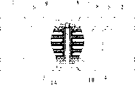
Fig. 1 is a structural representation of the present utility model;
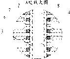
Fig. 2 is the A place enlarged drawing of Fig. 1;
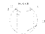
Fig. 3 is a user mode reference diagram of the present utility model;
Fig. 4 is the B place enlarged drawing of Fig. 3;
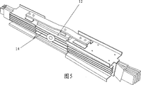
Fig. 5 is an another kind of user mode reference diagram of the present utility model.
Embodiment
Referring to figs. 1 through Fig. 4, the bus duct jockey comprises metal side plate 1, collets 2, bolt 3 and conducting metal piece 5, described collets 2 be installed in respectively between metal side plate 1 and the conducting metal piece 5 and two blocks of adjacent conductive metal derbies 5 between.Metal side plate 1, collets 2 and conducting metal piece 5 have is convenient to the circular hole that bolt 3 passes, and bolt 3 is fixed on metal side plate 1, collets 2 and conducting metal piece 5 in the metal side plate 1 by being connected with the nut 9,10 of 1 liang of metal side plate of metal side plate.In order to prevent to produce between phase and phase the phenomenon of short circuit, be with insulated tube 4 on the described bolt 3, guaranteed dependability of the present utility model.As long as the conductor tab 11 of the every phase of bus duct is placed separately independently between the conducting metal piece 5 and collets 2, fix by bolt 3 then and just can form the whole piece bus duct, therefore the utlity model has advantage easy for installation, and the conductor tab 11 of bus duct is that face contacts completely with conducting metal piece 5, conductor tab 11 closely is connected with conducting metal piece 5, thereby prevent the appearance of electric discharge phenomena effectively, guaranteed security performance of the present utility model.
Wherein, the conducting metal piece 5 that is installed between the adjacent collets 2 is two, and the conductor tab of bus duct 11 adopts two-sided contact, and the conductor tab 11 of bus duct closely is connected with conducting metal piece 5, the electric property that assurance conductor tab 11 is good.
A surface of described conducting metal piece 5 is provided with projection 6, the back side of projection 6 is groove 7, projection 6 butt joints of two conducting metal pieces 5, projection 6 height is less than half of bus duct conductor tab, adjacent two conducting metal pieces 5 are strutted by projection 6, guarantee that the conductor tab 11 of bus duct closely is connected with conducting metal piece 5 when making things convenient for bus duct conductor tab 11 to insert with this.Wherein, described protruding 6 be located at insulated tube 4 around, it is shaped as annular, improves reliability of the present utility model.
In order to make conducting metal fast 5 be connected with the conductor tab 11 of bus duct more closely, prevent that rainwater from entering jockey from the gap of insulated tube 4, in the described groove 7, on the insulated tube 4 heat-resisting flexible rubber ring 8 is installed.
The upper and lower side of described metal side plate 1 is connected with metal cover board 12 by securing member, and metal cover board 12 is equipped with sealing strip with the contact-making surface of metal side plate 1, and described sealing strip places on the groove 13 of metal side plate 1.Be socketed with rubber ring on the projection 15 of bus duct end, described rubber ring is clamped the whole piece bus duct system that forms as shown in Figure 4 by metal cover board 12 and metal side plate 1; Thereby prevent that effectively rainwater from entering in the jockey.
With reference to Fig. 5, described metal side plate is provided with protrudes its surperficial fin 14, and this fin 14 distributes the heat of conducting metal piece and the generation of bus duct conductor tab; And the fin 14 of projection can play the intensity of reinforcement metal side plate, when causing tightening bolt, metal side plate can be evenly distributed to this strength on the contact-making surface of conductor tab, thereby it is tightr to guarantee that the conducting metal piece is connected with the bus duct conductor tab, has guaranteed the conductive capability of conductor.
In a word, be equal to the utility model or similar technical scheme or the utility model improved, but the technical scheme of having had to comprise described all technical characterictics of claim 1 of the present utility model also belongs to protection range of the present utility model.
Claims (8)
1, bus duct jockey, comprise metal side plate (1), be installed in collets (2) in the metal side plate (1), connect the bolt (3) of collets (2) and metal side plate (1) and be enclosed within insulated tube (4) on the bolt (3), it is characterized in that: conducting metal piece (5) is installed between the collets (2).
2, bus duct jockey according to claim 1 is characterized in that: the conducting metal piece (5) that is installed between the adjacent collets (2) is two.
3, bus duct jockey according to claim 2, it is characterized in that: a surface of described conducting metal piece (5) is provided with projection (6), the back side of projection (6) is groove (7), the butt joint of the projection (6) of two conducting metal pieces (5), the height of projection (6) is less than half of bus duct conductor tab (11).
4, bus duct jockey according to claim 3 is characterized in that: described projection (6) be located at insulated tube (4) around, it is shaped as annular.
5, bus duct jockey according to claim 3 is characterized in that: in the described groove (7), on the insulated tube (4) heat-resisting flexible rubber ring (8) is installed.
6, bus duct jockey according to claim 1 is characterized in that: the upper and lower side of described metal side plate (1) is connected with metal cover board (12) by securing member, and metal cover board (12) is equipped with sealing strip with the contact-making surface of metal side plate (1).
7, bus duct jockey according to claim 6 is characterized in that: described sealing strip places on the groove (13) of metal side plate (1).
8, according to claim 1 or 6 or 7 described bus duct jockeys, it is characterized in that: described metal side plate (1) is provided with protrudes its surperficial fin (14).
Priority Applications (1)
| Application Number | Priority Date | Filing Date | Title |
|---|---|---|---|
| CN 200520060302 CN2829168Y (en) | 2005-06-28 | 2005-06-28 | Bus-bar groove connection device |
Applications Claiming Priority (1)
| Application Number | Priority Date | Filing Date | Title |
|---|---|---|---|
| CN 200520060302 CN2829168Y (en) | 2005-06-28 | 2005-06-28 | Bus-bar groove connection device |
Publications (1)
| Publication Number | Publication Date |
|---|---|
| CN2829168Y true CN2829168Y (en) | 2006-10-18 |
Family
ID=37080719
Family Applications (1)
| Application Number | Title | Priority Date | Filing Date |
|---|---|---|---|
| CN 200520060302 Expired - Fee Related CN2829168Y (en) | 2005-06-28 | 2005-06-28 | Bus-bar groove connection device |
Country Status (1)
| Country | Link |
|---|---|
| CN (1) | CN2829168Y (en) |
Cited By (9)
| Publication number | Priority date | Publication date | Assignee | Title |
|---|---|---|---|---|
| CN102810832A (en) * | 2012-08-14 | 2012-12-05 | 江苏华威线路设备集团有限公司 | Busway connector |
| CN102820560A (en) * | 2012-08-08 | 2012-12-12 | 江苏万奇电器集团有限公司 | Device and method for butting single-phase single-sheet transition conductor of bus duct connector |
| CN102856673A (en) * | 2012-07-30 | 2013-01-02 | 江苏万奇电器集团有限公司 | Bus duct joint conductor current-carrying compensation connecting link |
| CN102856674A (en) * | 2012-07-30 | 2013-01-02 | 江苏万奇电器集团有限公司 | Single insert sheet type bus duct conductor joint |
| CN102946009A (en) * | 2012-07-30 | 2013-02-27 | 江苏万奇电器集团有限公司 | Double-insert-sheet type bus duct conductor joint |
| CN105914681A (en) * | 2016-06-02 | 2016-08-31 | 江苏大浪电气制造有限公司 | Bus duct connector |
| CN106451284A (en) * | 2016-10-28 | 2017-02-22 | 江苏万奇电器集团有限公司 | Joint sealing sleeve for bus duct pouring |
| CN106785945A (en) * | 2016-12-28 | 2017-05-31 | 汉舟四川铜铝复合科技有限公司 | One kind is for busbar channel in cabinet and switch disconnector attachment means |
| CN107516863A (en) * | 2017-10-12 | 2017-12-26 | 威腾电气集团股份有限公司 | A kind of high voltage bus Special heat dissipating type bus duct |
-
2005
- 2005-06-28 CN CN 200520060302 patent/CN2829168Y/en not_active Expired - Fee Related
Cited By (13)
| Publication number | Priority date | Publication date | Assignee | Title |
|---|---|---|---|---|
| CN102856674B (en) * | 2012-07-30 | 2015-04-15 | 江苏万奇电器集团有限公司 | Single insert sheet type bus duct conductor joint |
| CN102856673A (en) * | 2012-07-30 | 2013-01-02 | 江苏万奇电器集团有限公司 | Bus duct joint conductor current-carrying compensation connecting link |
| CN102856674A (en) * | 2012-07-30 | 2013-01-02 | 江苏万奇电器集团有限公司 | Single insert sheet type bus duct conductor joint |
| CN102946009A (en) * | 2012-07-30 | 2013-02-27 | 江苏万奇电器集团有限公司 | Double-insert-sheet type bus duct conductor joint |
| CN102856673B (en) * | 2012-07-30 | 2014-10-22 | 江苏万奇电器集团有限公司 | Bus duct joint conductor current-carrying compensation connecting link |
| CN102946009B (en) * | 2012-07-30 | 2015-07-29 | 江苏万奇电器集团有限公司 | A kind of two blade inserting bus duct conductor tab |
| CN102820560A (en) * | 2012-08-08 | 2012-12-12 | 江苏万奇电器集团有限公司 | Device and method for butting single-phase single-sheet transition conductor of bus duct connector |
| CN102810832A (en) * | 2012-08-14 | 2012-12-05 | 江苏华威线路设备集团有限公司 | Busway connector |
| CN105914681A (en) * | 2016-06-02 | 2016-08-31 | 江苏大浪电气制造有限公司 | Bus duct connector |
| CN106451284A (en) * | 2016-10-28 | 2017-02-22 | 江苏万奇电器集团有限公司 | Joint sealing sleeve for bus duct pouring |
| CN106785945A (en) * | 2016-12-28 | 2017-05-31 | 汉舟四川铜铝复合科技有限公司 | One kind is for busbar channel in cabinet and switch disconnector attachment means |
| CN106785945B (en) * | 2016-12-28 | 2019-04-23 | 汉舟四川铜铝复合科技有限公司 | One kind is for busbar channel in cabinet and switch disconnector attachment device |
| CN107516863A (en) * | 2017-10-12 | 2017-12-26 | 威腾电气集团股份有限公司 | A kind of high voltage bus Special heat dissipating type bus duct |
Similar Documents
| Publication | Publication Date | Title |
|---|---|---|
| CN2829168Y (en) | Bus-bar groove connection device | |
| CN208423241U (en) | A kind of cable branch terminal equipped with protection structure | |
| CN105470885A (en) | Novel bus duct tapping device | |
| CN205429234U (en) | High performance aluminum alloy cable junction terminal | |
| CN207603147U (en) | Bus duct transfiguration linkage structure | |
| CN109586055A (en) | A kind of joint structure | |
| CN104008929B (en) | A kind of face contact plug in circuit breaker | |
| CN201699145U (en) | Copper bar by utilizing fastening knurled nut to connect conducting wire and bus | |
| CN205303727U (en) | Wrap up in general formula parallel groove clamp | |
| CN203277688U (en) | Novel jointing clamp | |
| CN203967714U (en) | Multi-functional cable water joint | |
| CN103311685A (en) | Wire branch connector | |
| CN2779691Y (en) | Electric cable distribution box | |
| CN2788426Y (en) | Multi-direction and multi-circuit combined junction box | |
| CN201698915U (en) | Explosion-proof vacuum electromagnetic starter for mining | |
| CN207381537U (en) | A kind of 32 spring-piece type terminal boards | |
| CN201853817U (en) | Wire clamp for power distribution equipment | |
| CN201392890Y (en) | Low-voltage joint | |
| CN105490044A (en) | Wrapped parallel groove clamp for unstrained wire connection of electric power circuit | |
| CN205790698U (en) | A kind of anti-virtual connection binding post | |
| CN202172048U (en) | Wiring apparatus of universal circuit breaker | |
| CN2852342Y (en) | Conductive casing for transformer | |
| CN212751330U (en) | Bus switching assembly | |
| CN217956183U (en) | Four-point contact terminal for intelligent electric meter connector | |
| CN212113600U (en) | Connecting terminal of omega-shaped contact piece |
Legal Events
| Date | Code | Title | Description |
|---|---|---|---|
| C14 | Grant of patent or utility model | ||
| GR01 | Patent grant | ||
| C17 | Cessation of patent right | ||
| CF01 | Termination of patent right due to non-payment of annual fee |
Granted publication date: 20061018 Termination date: 20120628 |