CN2575813Y - Fast starting inductance ballast - Google Patents
Fast starting inductance ballast Download PDFInfo
- Publication number
- CN2575813Y CN2575813Y CN 02256482 CN02256482U CN2575813Y CN 2575813 Y CN2575813 Y CN 2575813Y CN 02256482 CN02256482 CN 02256482 CN 02256482 U CN02256482 U CN 02256482U CN 2575813 Y CN2575813 Y CN 2575813Y
- Authority
- CN
- China
- Prior art keywords
- epoxy resin
- resin dipping
- core body
- high voltage
- insulation core
- Prior art date
- Legal status (The legal status is an assumption and is not a legal conclusion. Google has not performed a legal analysis and makes no representation as to the accuracy of the status listed.)
- Expired - Lifetime
Links
- 238000009413 insulation Methods 0.000 claims abstract description 78
- 239000003822 epoxy resin Substances 0.000 claims abstract description 70
- 229920000647 polyepoxide Polymers 0.000 claims abstract description 70
- 238000007598 dipping method Methods 0.000 claims abstract description 63
- 239000000835 fiber Substances 0.000 claims abstract description 63
- 239000003990 capacitor Substances 0.000 claims abstract description 37
- 229920000049 Carbon (fiber) Polymers 0.000 claims abstract description 11
- 239000004917 carbon fiber Substances 0.000 claims abstract description 11
- VNWKTOKETHGBQD-UHFFFAOYSA-N methane Chemical compound C VNWKTOKETHGBQD-UHFFFAOYSA-N 0.000 claims abstract description 11
- 239000004745 nonwoven fabric Substances 0.000 claims abstract description 11
- 239000002184 metal Substances 0.000 claims description 40
- 229910052751 metal Inorganic materials 0.000 claims description 40
- 239000004020 conductor Substances 0.000 claims description 21
- 229920001971 elastomer Polymers 0.000 claims description 19
- 239000012212 insulator Substances 0.000 claims description 16
- 230000007704 transition Effects 0.000 claims description 14
- 230000005684 electric field Effects 0.000 claims description 11
- 230000004888 barrier function Effects 0.000 claims description 8
- WABPQHHGFIMREM-UHFFFAOYSA-N lead(0) Chemical compound [Pb] WABPQHHGFIMREM-UHFFFAOYSA-N 0.000 claims description 7
- 239000011248 coating agent Substances 0.000 claims description 6
- 238000000576 coating method Methods 0.000 claims description 6
- 239000003365 glass fiber Substances 0.000 claims description 6
- 239000000463 material Substances 0.000 claims description 6
- 239000006260 foam Substances 0.000 claims description 5
- 239000011810 insulating material Substances 0.000 claims description 4
- 230000015572 biosynthetic process Effects 0.000 claims description 3
- 238000005259 measurement Methods 0.000 claims description 3
- 229910052573 porcelain Inorganic materials 0.000 claims description 3
- 125000006850 spacer group Chemical group 0.000 claims description 3
- 229920000260 silastic Polymers 0.000 claims description 2
- 238000000034 method Methods 0.000 abstract description 6
- OKTJSMMVPCPJKN-UHFFFAOYSA-N Carbon Chemical compound [C] OKTJSMMVPCPJKN-UHFFFAOYSA-N 0.000 abstract description 3
- 230000008569 process Effects 0.000 abstract description 3
- 230000003247 decreasing effect Effects 0.000 abstract 1
- 230000002349 favourable effect Effects 0.000 abstract 1
- 239000004850 liquid epoxy resins (LERs) Substances 0.000 abstract 1
- 238000000926 separation method Methods 0.000 abstract 1
- 238000004046 wet winding Methods 0.000 abstract 1
- 238000004804 winding Methods 0.000 description 8
- RYGMFSIKBFXOCR-UHFFFAOYSA-N Copper Chemical compound [Cu] RYGMFSIKBFXOCR-UHFFFAOYSA-N 0.000 description 4
- 229910052802 copper Inorganic materials 0.000 description 4
- 239000010949 copper Substances 0.000 description 4
- 238000010586 diagram Methods 0.000 description 4
- 239000004922 lacquer Substances 0.000 description 4
- 239000003921 oil Substances 0.000 description 4
- 239000004593 Epoxy Substances 0.000 description 3
- 239000011521 glass Substances 0.000 description 3
- -1 polytetrafluoroethylene Polymers 0.000 description 3
- 229920001343 polytetrafluoroethylene Polymers 0.000 description 3
- 239000004810 polytetrafluoroethylene Substances 0.000 description 3
- 238000009954 braiding Methods 0.000 description 2
- 229910052799 carbon Inorganic materials 0.000 description 2
- 230000008878 coupling Effects 0.000 description 2
- 238000010168 coupling process Methods 0.000 description 2
- 238000005859 coupling reaction Methods 0.000 description 2
- 230000005611 electricity Effects 0.000 description 2
- 230000006872 improvement Effects 0.000 description 2
- 238000012423 maintenance Methods 0.000 description 2
- 238000004519 manufacturing process Methods 0.000 description 2
- 229920002379 silicone rubber Polymers 0.000 description 2
- 229910001220 stainless steel Inorganic materials 0.000 description 2
- 239000010935 stainless steel Substances 0.000 description 2
- 239000000853 adhesive Substances 0.000 description 1
- 230000001070 adhesive effect Effects 0.000 description 1
- 239000005030 aluminium foil Substances 0.000 description 1
- 230000008859 change Effects 0.000 description 1
- 230000007812 deficiency Effects 0.000 description 1
- 230000002950 deficient Effects 0.000 description 1
- 238000013461 design Methods 0.000 description 1
- 238000003618 dip coating Methods 0.000 description 1
- 238000009826 distribution Methods 0.000 description 1
- 230000000694 effects Effects 0.000 description 1
- 238000004070 electrodeposition Methods 0.000 description 1
- 238000005516 engineering process Methods 0.000 description 1
- 239000011152 fibreglass Substances 0.000 description 1
- LNEPOXFFQSENCJ-UHFFFAOYSA-N haloperidol Chemical compound C1CC(O)(C=2C=CC(Cl)=CC=2)CCN1CCCC(=O)C1=CC=C(F)C=C1 LNEPOXFFQSENCJ-UHFFFAOYSA-N 0.000 description 1
- 238000009434 installation Methods 0.000 description 1
- 230000004048 modification Effects 0.000 description 1
- 238000012986 modification Methods 0.000 description 1
- 238000007711 solidification Methods 0.000 description 1
- 230000008023 solidification Effects 0.000 description 1
- 230000009466 transformation Effects 0.000 description 1
Images


Landscapes
- Insulating Bodies (AREA)
Abstract
The utility model relates to a dipping epoxy resin fiber high voltage insulating core body which comprises a conductive body which is arranged in the center of the insulating core body, a dipping epoxy resin fiber insulating body with a capacitor pole plate, which is composed of dipping epoxy resin fiber layers alternately coated at the surface of the periphery of the conductive body and the capacitor pole plate, and an umbrella-shaped outer sheath which is coated at the surface of the periphery of the dipping epoxy resin fiber insulating body, wherein the capacitor pole plate is composed of a wire mesh or carbon fiber nonwoven fabric, and favorable bonding strength is formed between the capacitor pole plate and the dipping epoxy resin fiber layers; separation layer gaps are not easy to generate among the adjacent epoxy resin fiber layers; the wire mesh or the carbon fiber nonwoven fabric has high-low temperature resistance performance and has stable performance for running chronically; the wire mesh or the carbon fiber nonwoven fabric can be used as a capacitor screen and can prevent carbon powder from falling or mixing in liquid epoxy resin in the process of wet winding. The utility model ensures that the insulation level of the epoxy resin fiber layers can not be decreased.
Description
Technical field:
The present invention relates to a kind of epoxy resin dipping fibre high voltage insulation core body, it is a critical piece in the High-Voltage Electrical Appliances, main as the insulation core body that high-tension electricity is passed the earth electrode position, insulation core body as wall bushing, bushing shell for transformer, switch sleeve pipe etc., the insulation core body of a winding of instrument transformer, the insulation core body of cable terminal and cable mid head etc.
Background technology:
The High-Voltage Electrical Appliances insulation core body of prior art has following several: (1) paper oil insulation core body.For example traditional wall bushing, bushing shell for transformer, current transformer etc. mostly adopt the paper oil insulation core body, and the paper bag that the centre is accompanied metal polar plate is on carrying object, and the insulation core body of formation is loaded in the porcelain bushing that is full of insulating oil; (2) fill SF6 gas-insulated core body; (3) rubber-covered core body; (4) polytetrafluoroethylene film insulation core body.For example, the insulation core body in the organic insulation dry type wall bushing that occurs in recent years, dry-type current transformer, the dry-type cable terminal all with polytetrafluoroethylene film at interval Aluminium Foil Package have mercy on the carrying object, constitute on the metallic framework or on the cable insulation surface.There is leakage problems in the product that the insulation core body of paper oil insulation core body and inflation body medium is formed, not only contaminated environment, increased a lot of maintenance workloads, also power system security is constituted a latent danger.The stress cone of cable terminal can be considered the rubber-covered core body, though the effect of electric field of improvement is arranged, Electric Field Distribution is even not enough, often has the stress awl to puncture the accident that causes the cable end blast for these years.The polytetrafluoroethylene film insulation core body has had very big progress, and security performance is good, and maintenance workload is little, but the material price height is unfavorable for wideling popularize.
At present, a kind of pure dry type wall bushing appears on the market, the capacitance core formula insulator that employing is made of the alternate coiling with semi-conductive tape of glass fibre of dip-coating epoxy resin, because of the wettability of semi-conductive tape relatively poor, with the defective tightness that combines of epoxy fibreglass, between adjacent epoxy glass layer the absciss layer slit appears easily; Moreover, do capacitance plate with semi-conductive tape, in the wet method winding process, the time have powdered carbon to fall into or sneak in the liquid-state epoxy resin, cause epoxy glass fiber layer insulation level to descend, influence the electric property of equipment.
Summary of the invention:
Purpose of the present invention, be intended to overcome the deficiency of above-mentioned prior art, a kind of epoxy resin dipping fibre high voltage insulation core body of improvement is provided, capacitance pole flaggy in its main insulation and the epoxy resin dipping fibre layer not absciss layer of can combining closely, can also high-low temperature resistant, the assurance insulating barrier is pure, thereby improves electric property, mechanical strength and the useful life of product.
According to epoxy resin dipping fibre high voltage insulation core body provided by the invention, comprise the electric conductor that is arranged at the insulation core body center, overlay on the epoxy resin dipping fibre layer of electric conductor outer surface and the epoxy resin dipping fibre insulator that capacitor plate constitutes the capacitor pole plate by alternating packets, be coated on the umbrella shape oversheath of epoxy resin dipping fibre insulator outer surface, described capacitor plate is made of woven wire or carbon fiber bar nonwoven fabrics.
After described epoxy resin dipping fibre layer was multiply glass fibre or other organic insulation fiber epoxy resin dippings, the hoop formula is wound in had certain thickness insulating barrier.
Described electric conductor can be placed in its outer high-resistance metal pipe or rubber tube by metal conducting bar or insulation cable, and close attachment constitutes at the semiconductive transition zone of described high-resistance metal pipe or rubber tube outer surface.
Described electric conductor also can be made of at the semiconductive transition zone of described metal conducting bar or metal tube outer surface metal conducting bar or metal tube and close attachment.
Described semiconductive transition zone can be the semiconductive heat-shrink tube, also can be the semiconductive single-coated foam.
Described metal conducting bar that passes metal tube or rubber tube or insulation cable, the one end be placed in that its outer metal tube is electrically connected or be electrically connected with semiconductive transition zone on the rubber tube outer surface, the other end insulate, the shape of electric conductor is shape or U-shaped linearly.
As preferred version, the edge of capacitor plate preferably is provided with stress loop or stress limit.Described stress loop and stress limit are the ring-type or the strip-shaped parts of conducting electricity or semiconductive material is made, and the capacitor plate edge is pushed down on described stress loop or stress limit.
As preferred version, the uneven position of outer surface electric field strength that is preferably in the epoxy resin dipping fibre insulator of capacitor pole plate is provided with the nonlinear resistance coating.
As preferred version, be preferably in short end screen is set between the high and adjacent capacitor plate of electric field strength.
The epoxy resin dipping fibre insulator of described capacitor pole plate is symmetric figure linearly, perhaps the asymmetric shape of straight line, perhaps U font.
Compared with the prior art, the present invention has the following advantages:
1, the present invention is because in the epoxy resin dipping fibre insulator of capacitor pole plate, adopt woven wire or the such two kinds of electric conductors of carbon fiber bar nonwoven fabrics to make capacitor plate, woven wire or carbon fiber bar nonwoven fabrics and epoxy resin dipping fibre layer have good adhesive strength, are not prone to the absciss layer slit between the adjacent ring epoxy resins glass layer; Woven wire or carbon fiber bar nonwoven fabrics have the performance of high-and low-temperature resistance, during long-time running, and stable performance; Do capacitance plate with woven wire or carbon fiber bar nonwoven fabrics, in the wet method winding process, the situation that can avoid powdered carbon to fall into or sneak into liquid-state epoxy resin takes place, epoxy resin fiber layer insulation level can not descend, the equipment of assurance has good electric property, has improved the rate of finished products and the useful life of product.
2, the electric conductor 1 that the present invention is alleged, mean the conductive component that is arranged at above-mentioned insulation core body center, rather than the conductor of general meaning, more particularly, this electric conductor can be placed in its outer high-resistance metal pipe or rubber tube 16 by metal conducting bar or insulation cable 15, and close attachment constitutes at the semiconductive transition zone 6 of described high-resistance metal pipe or rubber tube 16 outer surfaces.This combination has product applicability, interchangeability widely, if change conducting rod can satisfy sleeve pipe different pass through current requirements; As long as this combination penetrates the insulation cable of different radicals and changes the mode of connection, can satisfy the different current ratio requirement of current transformer; As long as being pressed into the power cable of shelling to insulating barrier, this combination promptly can be used as cable terminal.
3, the fibrage 7 of epoxy resin dipping of the present invention can be multiply glass fibre or other organic insulation fibers, behind the epoxy resin dipping, the hoop formula is wound in has certain thickness insulating barrier, this hoop formula canoe can make fiber alignment tightr than spiral winding, thickness of insulating layer is more even, and capacitance is more accurate, and rate of finished products is higher.
4, as a kind of preferred version of the present invention, the edge that is preferably in capacitor plate 8 is provided with stress loop 9 or stress limit 10, can effectively improve electric field, and evenly field intensity reduces partial discharge quantity.
5, as the another kind of preferred version of the present invention, the high position of outer surface electric field strength that is preferably in the epoxy resin dipping fibre insulator 2 of capacitor pole plate is provided with nonlinear resistance coating 13.This nonlinear resistance coating 13 can adopt the nonlinear resistance lacquer.In order to force improving axial electric field, voltage is evenly distributed, improve insulation level.
Description of drawings:
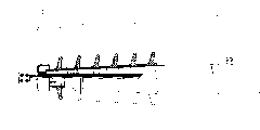
Fig. 1 is according to the present invention, is used for the U-shaped epoxy resin dipping fibre high voltage insulation core body schematic diagram of a winding of current transformer;
Fig. 2 is according to the present invention, is used for the straight line symmetric figure epoxy resin dipping fibre high voltage insulation core body schematic diagram of wall bushing;
Fig. 3 is according to the present invention, is used for the asymmetric shape epoxy resin dipping fibre high voltage insulation core body of the straight line schematic diagram of cable terminal.
Fig. 4 is according to the present invention, is used for the asymmetric shape epoxy resin dipping fibre high voltage insulation core body of the straight line schematic diagram of transformer;
Embodiment:
Referring to Fig. 1 to 4, wherein provide according to several epoxy resin dipping fibre high voltage insulation core bodies of the present invention, comprise the electric conductor 1 that is arranged at the insulation core body center, overlay on the epoxy resin dipping fibre layer 7 of electric conductor 1 outer surface and the epoxy resin dipping fibre insulator 2 that capacitor plate 8 constitutes the capacitor pole plate by alternating packets, be coated on the umbrella shape oversheath 3 of epoxy resin dipping fibre insulator 2 outer surfaces, the notable feature that the present invention is different from prior art is: described capacitor plate 8 is made of woven wire or carbon fiber bar nonwoven fabrics.
The fibrage 7 of described epoxy resin dipping can be multiply glass fibre or other organic insulation fibers, and behind the epoxy resin dipping, the hoop formula is wound in has certain thickness insulating barrier.
The electric conductor 1 that the present invention is alleged, mean the conductive component that is arranged at above-mentioned insulation core body center, rather than the conductor of general meaning, more particularly, this electric conductor can be by metal conducting bar or insulation cable 15, be placed in its outer high-resistance metal pipe or rubber tube 16, and close attachment constitutes at the semiconductive transition zone 6 of described high-resistance metal pipe or rubber tube 16 outer surfaces.Above-mentioned insulation cable can form with the power cable transformation of the way of shelling to insulating barrier.Need to prove that the high-resistance metal pipe both had been suitable for cooperating with metal conducting bar, also be suitable for being used with the insulation cable; And rubber tube then is suitable for the insulation cable to be used, and is first-class as cable termination.
As a kind of alternative, described electric conductor 1 also can be made of at the semiconductive transition zone 6 of described metal conducting bar or metal tube outer surface metal conducting bar or metal tube and close attachment.
Above-mentioned semiconductive transition zone 6 can be semiconductive heat-shrink tube or semiconductive single-coated foam.
As a kind of preferred version, the edge that is preferably in capacitor plate 8 is provided with stress loop 9 or stress limit 10, and described stress loop 9 and stress limit 10 are ring-type or strip-shaped parts made from conduction or semiconductive material, and push down the capacitor plate edge.
As another kind of preferred version, the high position of outer surface electric field strength that is preferably in the epoxy resin dipping fibre insulator 2 of capacitor pole plate is provided with nonlinear resistance coating 13.This nonlinear resistance coating 13 can adopt the nonlinear resistance lacquer.
As another preferred version, be preferably in short end screen is set between the high and adjacent capacitor plate of electric field strength.
Above-mentioned metal conducting bar or the insulation cable that penetrates metal tube or rubber tube, the one end can be electrically connected with metal tube by a conducting ring, perhaps utilize known method to be electrically connected with semiconductive transition zone on the rubber tube outer surface, the other end can be supported in the metal tube with insulation mode by a spacer sleeve with the insulating material manufacturing as shown in the figure.The shape of electric conductor 1, shape linearly when as the epoxy resin dipping fibre high voltage insulation core body of wall bushing, bushing shell for transformer, switch sleeve pipe or cable terminal, and take the shape of the letter U during as the epoxy resin dipping fibre high voltage insulation core body of a winding of current transformer.
Above-mentioned umbrella shape oversheath 3 is made by silastic material, can global formation or bonding the forming of a plurality of single umbrellas.
Can adopt a constant force spring 11 that measuring lead wire 12 is fastened on the outermost layer capacitor plate, the other end of measuring lead wire is connected on the measurement terminal of being made by organic insulating material or porcelain 5.Parts commonly used in wall bushing, bushing shell for transformer, switch sleeve pipe, the current transformer can also be set, as device clamp 4 and grading shield 14 etc., because these parts are that those of ordinary skill in the art knows, and irrelevant with the present invention, this specification repeats no more.
The epoxy resin dipping fibre insulator (2) of above-mentioned capacitor pole plate symmetric figure linearly when the time as high-voltage wall bushing, switch sleeve pipe, linearly asymmetric shape when as bushing shell for transformer, cable termination is the U font when as winding of current transformer.
Example one:
Now the high voltage insulation core body with 110kV, 1000A wall bushing is an example, and the making step of epoxy resin dipping fibre high voltage insulation core body of the present invention is described:
A, to select diameter be that Φ 30 conducting rods are packed in the high-resistance metal pipe of external diameter Φ 49, internal diameter Φ 42, and an end is fixed with the metallic conduction ring, and the other end is fixed with the spacer sleeve of insulating material manufacturing;
B, outside metal tube pyrocondensation semiconductive heat-shrink tube or twine the semiconductive single-coated foam;
C, above-mentioned workpiece are contained on the automatic special purpose machine tool;
D, under Clean room or vacuum state, hold the glass layer of the thick epoxy resin dipping of about 3mm automatically;
E, hold the thick capacitor plate of about 0.15mm at Clean room, optional banded winding of woven wire, the carbon fiber bar nonwoven fabrics can lay with whole and wrap, and stress limit or stress loop are installed additional in edge;
F, d to e step 15 time repeatedly, the thick 2mm of end layer screen;
G, insert in the baking oven temperature curve dry solidification by design.
H, at the cylindrical of the long 100mm of screen middle part, end turning, expose the end and shield woven wire;
I, closely be connected with end screen woven wire with constant force spring chucking copper braiding measuring lead wire, the other end connection measurement terminal of copper braiding measuring lead wire, and be fixed on the high voltage insulation core body middle part surface;
J, the high position of selection field intensity are provided with the nonlinear resistance lacquer vertically.
K, the silicon rubber full skirt is bonded on the unsheltered high voltage insulation core body of the coupling tunnel surface.
Example two:
High voltage insulation core body with 110kV, 600A cable terminal is an example again, and the making step of epoxy resin dipping fibre high voltage insulation core body of the present invention is described:
A, with the fixing rubber tube of mold;
B, hold the semiconductive single-coated foam on the rubber tube surface.
Below identical with example one step c-h.
I, constant force spring chucking copper litz wire closely are connected with end screen woven wire, and the other end of copper litz wire is connected with the cable grounding guard box.
J, the high position of selection field intensity are provided with the nonlinear resistance lacquer vertically.
K, the silicon rubber full skirt is bonded on the unsheltered high voltage insulation core body of the coupling tunnel surface.
L, extract the mold in the rubber tube out, will shell during installation to the power cable of insulating barrier and be pressed in the rubber tube, and cable is led core do with the semiconductive transition zone and be electrically connected.
Example three:
High voltage insulation core body with 110kV, 600A current transformer is an example again, and the making step of epoxy resin dipping fibre high voltage insulation core body of the present invention is described:
A, the stainless steel tube of Φ 50 that will wear conducting rod or insulation cable with mold curve U-shaped, and an end of conducting rod or insulation cable is electrically connected with stainless steel tube, and the other end insulate;
The semiconductive heat-shrink tube that b, metal tube external contracting 2mm are thick;
C, above-mentioned workpiece is contained on the special purpose machine tool the holding head and can rotate and can regulate and control arbitrarily of this lathe around workpiece at three dimensions.
D, the following step are identical with example one.
The foregoing description is explanation the present invention's usefulness only, and is not to be limitation of the present invention.The those of ordinary skill in relevant field on this basis, can also be made multiple variation or modification, and not break away from the spirit and scope of the present invention.Protection scope of the present invention should be as the criterion with the content of claim.
Claims (15)
1, a kind of epoxy resin dipping fibre high voltage insulation core body, comprise the electric conductor (1) that is arranged at the insulation core body center, overlay on the epoxy resin dipping fibre layer (7) of electric conductor (1) outer surface and the epoxy resin dipping fibre insulator (2) that capacitor plate (8) constitutes the capacitor pole plate by alternating packets, be coated on the umbrella shape oversheath (3) of epoxy resin dipping fibre insulator (2) outer surface, it is characterized in that: described capacitor plate (8) is made of woven wire or carbon fiber bar nonwoven fabrics.
2, according to the described epoxy resin dipping fibre high voltage insulation core body of claim 1, it is characterized in that: described electric conductor (1) is by metal conducting bar or insulation cable (15), be placed in its outer high-resistance metal pipe or rubber tube (16), and close attachment constitutes at the semiconductive transition zone (6) of described high-resistance metal pipe or rubber tube (16) outer surface.
3, according to the described epoxy resin dipping fibre high voltage insulation core body of claim 1, it is characterized in that: described electric conductor (1) is made of at the semiconductive transition zone (6) of described metal conducting bar or metal tube outer surface metal conducting bar or metal tube and close attachment.
4, according to the described epoxy resin dipping fibre high voltage insulation core body of claim 1, it is characterized in that: the edge of capacitor plate (8) is provided with stress loop (9) or stress limit (10).
5, according to the described epoxy resin dipping fibre high voltage insulation core body of claim 1, it is characterized in that: the high position of outer surface electric field strength at the epoxy resin dipping fibre insulator (2) of capacitor pole plate is provided with nonlinear resistance coating (13).
6, according to the described epoxy resin dipping fibre high voltage insulation core body of claim 2, it is characterized in that: the metal conducting bar or the insulation cable that penetrate metal tube or rubber tube, the one end is electrically connected with metal tube or is electrically connected with semiconductive transition zone on the rubber tube outer surface, the other end insulate with spacer sleeve (18), and the shape of electric conductor (1) is shape or U-shaped linearly.
7, according to claim 2 or 3 described epoxy resin dipping fibre high voltage insulation core bodies, it is characterized in that: described semiconductive transition zone (6) is semiconductive heat-shrink tube or semiconductive single-coated foam.
8, according to the described epoxy resin dipping fibre high voltage insulation core body of claim 1, it is characterized in that: short end screen (17) is set between the high and adjacent capacitor plate of electric field strength.
9, according to the described epoxy resin dipping fibre high voltage insulation core body of claim 1, it is characterized in that: after the fibrage of described epoxy resin dipping (7) was multiply glass fibre or other organic insulation fiber epoxy resin dippings, the hoop formula is wound in had certain thickness insulating barrier.
10,, it is characterized in that described stress loop (9) and stress limit (10) are ring-type or the strip-shaped parts of being made by conduction or semiconductive material, and push down the capacitor plate edge according to the described epoxy resin dipping fibre high voltage insulation core body of claim 4.
11, according to the described epoxy resin dipping fibre high voltage insulation core body of claim 1, it is characterized in that: described umbrella shape oversheath (3) is made by silastic material, can global formation or bonding the forming of a plurality of single umbrellas.
12, according to the described epoxy resin dipping fibre high voltage insulation core body of claim 1, it is characterized in that: a constant force spring (11) is fastened on measuring lead wire (12) on the outermost layer capacitor plate, and the other end of measuring lead wire is connected on the measurement terminal of being made by organic insulating material or porcelain (5).
13, according to the described epoxy resin dipping fibre high voltage insulation core body of claim 1, it is characterized in that: also be provided with device clamp (4) and grading shield (14).
14, according to the described epoxy resin dipping fibre high voltage insulation core body of claim 7, it is characterized in that: the epoxy resin dipping fibre insulator (2) of capacitor pole plate is symmetric figure linearly, perhaps the asymmetric shape of straight line, perhaps U font.
15, according to each described epoxy resin dipping fibre high voltage insulation core body in the claim 1 to 6,8 to 16, it is characterized in that: the epoxy resin dipping fibre insulator (2) of capacitor pole plate is symmetric figure linearly, perhaps the asymmetric shape of straight line, perhaps U font.
Priority Applications (1)
| Application Number | Priority Date | Filing Date | Title |
|---|---|---|---|
| CN 02256482 CN2575813Y (en) | 2002-10-08 | 2002-10-08 | Fast starting inductance ballast |
Applications Claiming Priority (1)
| Application Number | Priority Date | Filing Date | Title |
|---|---|---|---|
| CN 02256482 CN2575813Y (en) | 2002-10-08 | 2002-10-08 | Fast starting inductance ballast |
Publications (1)
| Publication Number | Publication Date |
|---|---|
| CN2575813Y true CN2575813Y (en) | 2003-09-24 |
Family
ID=33724696
Family Applications (1)
| Application Number | Title | Priority Date | Filing Date |
|---|---|---|---|
| CN 02256482 Expired - Lifetime CN2575813Y (en) | 2002-10-08 | 2002-10-08 | Fast starting inductance ballast |
Country Status (1)
| Country | Link |
|---|---|
| CN (1) | CN2575813Y (en) |
Cited By (4)
| Publication number | Priority date | Publication date | Assignee | Title |
|---|---|---|---|---|
| CN103366907A (en) * | 2012-03-15 | 2013-10-23 | 西门子公司 | High-voltage wall bushing with conductive inserts and method for producing the wall bushing |
| CN105355344A (en) * | 2015-12-20 | 2016-02-24 | 西安神电高压电器有限公司 | High-voltage bushing and processing technology thereof |
| CN107768045A (en) * | 2017-10-31 | 2018-03-06 | 清华大学 | A kind of composite insulator with the equal laminated structure of nonlinear conductance material |
| US10937597B2 (en) | 2017-06-30 | 2021-03-02 | Abb Schweiz Ag | High voltage capacitive device |
-
2002
- 2002-10-08 CN CN 02256482 patent/CN2575813Y/en not_active Expired - Lifetime
Cited By (5)
| Publication number | Priority date | Publication date | Assignee | Title |
|---|---|---|---|---|
| CN103366907A (en) * | 2012-03-15 | 2013-10-23 | 西门子公司 | High-voltage wall bushing with conductive inserts and method for producing the wall bushing |
| CN103366907B (en) * | 2012-03-15 | 2016-08-24 | 西门子公司 | There is high pressure wall bushing and its manufacture method of conductive liner |
| CN105355344A (en) * | 2015-12-20 | 2016-02-24 | 西安神电高压电器有限公司 | High-voltage bushing and processing technology thereof |
| US10937597B2 (en) | 2017-06-30 | 2021-03-02 | Abb Schweiz Ag | High voltage capacitive device |
| CN107768045A (en) * | 2017-10-31 | 2018-03-06 | 清华大学 | A kind of composite insulator with the equal laminated structure of nonlinear conductance material |
Similar Documents
| Publication | Publication Date | Title |
|---|---|---|
| CN101339824B (en) | Composite insulating tube type bus and method for preparing the same | |
| RU2681643C1 (en) | Cable fittings for connecting a high-voltage cable with a high-voltage component | |
| CN105161230B (en) | Synthetic fibers strengthen resin high-pressure sleeve pipe | |
| CN103123825B (en) | High pressure and ultrahigh voltage flexible direct current transmission optical fiber compound extruded insulation submarine cable | |
| CN1195304C (en) | Epoxy resin dipping fibre high voltage insulation core body | |
| CN101436449B (en) | High-voltage and extra-high-voltage cables that can inhibit the formation and development of electrical trees inside the insulating layer | |
| CN201174264Y (en) | Tubular insulated busbar | |
| CN101572141A (en) | Cascade high-voltage bushing | |
| CN1186783C (en) | Dry-type high-voltage capacitor core and manufacturing method thereof | |
| CN204991304U (en) | Synthetic fiber reinforced resins high -tension bushing | |
| Lee et al. | Development of 250kV HVDC XLPE cable system in Korea | |
| CN2575813Y (en) | Fast starting inductance ballast | |
| CN2582240Y (en) | Dry, prefabricated and capacitance type cable terminal | |
| CN204904896U (en) | Novel aluminum alloy cable | |
| CN100449653C (en) | Lined high voltage insulating core | |
| CN110492425A (en) | A new type of indoor and outdoor terminal for high-voltage power cables | |
| CN202495281U (en) | Low skin effect extra-high voltage crosslinked cable | |
| CN109872848B (en) | Composite insulator and manufacturing method thereof, composite bushing | |
| CN215342160U (en) | Novel dry-type sleeve for electric power system | |
| CN203260363U (en) | High-voltage and extra-high voltage flexible direct-current power transmission fiber composite extrusion insulation submarine cable | |
| CN205959696U (en) | Novel structure extra -high voltage or super high voltage direct current insulator | |
| CN101866723B (en) | Method for manufacturing bent insulated busbar | |
| CN201699149U (en) | Connector of high-voltage isolated bus | |
| WO2015139736A1 (en) | A method for manufacturing a high-power cable | |
| CN217008817U (en) | Simple sleeve for glue-dipped fiber |
Legal Events
| Date | Code | Title | Description |
|---|---|---|---|
| C14 | Grant of patent or utility model | ||
| GR01 | Patent grant | ||
| AV01 | Patent right actively abandoned |
Effective date of abandoning: 20050330 |
|
| C25 | Abandonment of patent right or utility model to avoid double patenting |