CN2491663Y - Two-way single flow valve - Google Patents
Two-way single flow valve Download PDFInfo
- Publication number
- CN2491663Y CN2491663Y CN01225090.2U CN01225090U CN2491663Y CN 2491663 Y CN2491663 Y CN 2491663Y CN 01225090 U CN01225090 U CN 01225090U CN 2491663 Y CN2491663 Y CN 2491663Y
- Authority
- CN
- China
- Prior art keywords
- snap ring
- valve
- valve body
- water
- utility
- Prior art date
- Legal status (The legal status is an assumption and is not a legal conclusion. Google has not performed a legal analysis and makes no representation as to the accuracy of the status listed.)
- Expired - Lifetime
Links
- XLYOFNOQVPJJNP-UHFFFAOYSA-N water Substances O XLYOFNOQVPJJNP-UHFFFAOYSA-N 0.000 claims abstract description 61
- 208000002925 dental caries Diseases 0.000 claims 1
- 238000004519 manufacturing process Methods 0.000 abstract description 2
- 230000000694 effects Effects 0.000 description 4
- 230000035939 shock Effects 0.000 description 2
- 230000002411 adverse Effects 0.000 description 1
- 238000010438 heat treatment Methods 0.000 description 1
- 230000000737 periodic effect Effects 0.000 description 1
- 238000005381 potential energy Methods 0.000 description 1
Images


Classifications
-
- Y—GENERAL TAGGING OF NEW TECHNOLOGICAL DEVELOPMENTS; GENERAL TAGGING OF CROSS-SECTIONAL TECHNOLOGIES SPANNING OVER SEVERAL SECTIONS OF THE IPC; TECHNICAL SUBJECTS COVERED BY FORMER USPC CROSS-REFERENCE ART COLLECTIONS [XRACs] AND DIGESTS
- Y02—TECHNOLOGIES OR APPLICATIONS FOR MITIGATION OR ADAPTATION AGAINST CLIMATE CHANGE
- Y02E—REDUCTION OF GREENHOUSE GAS [GHG] EMISSIONS, RELATED TO ENERGY GENERATION, TRANSMISSION OR DISTRIBUTION
- Y02E10/00—Energy generation through renewable energy sources
- Y02E10/40—Solar thermal energy, e.g. solar towers
Landscapes
- Multiple-Way Valves (AREA)
Abstract
一种双向单流阀,主要由阀套(1),阀体(2),阀芯(3),上位卡环(4),下位卡环(5),水流腔体(6)组成,其中阀体(2)上制有旁通管口(21),给水孔(22),内置有上位卡环(4)和下位卡环(5),并阀芯(3)可在其间滑动,在阀体(2)之外装有阀套(1)构成水流腔体(6)。本实用新型用于太阳能系统工程中可实现系统管路的水自动排空功能,结构简单,易于制造,可制作多种规格系列产品,使用维护修理简易。
A two-way check valve, mainly composed of a valve sleeve (1), a valve body (2), a valve core (3), an upper snap ring (4), a lower snap ring (5), and a water flow cavity (6), wherein The valve body (2) is formed with a bypass nozzle (21), a water supply hole (22), and an upper snap ring (4) and a lower snap ring (5) are built in, and the valve core (3) can slide therebetween. A valve sleeve (1) is arranged outside the valve body (2) to form a water flow cavity (6). The utility model is used in solar energy system engineering to realize the automatic water emptying function of the system pipeline, has a simple structure, is easy to manufacture, can produce series products of various specifications, and is easy to use, maintain and repair.
Description
本实用新型涉及一种用于供水系统的特种阀门,尤其是用于停泵,控制回水旁道回流的双向单流阀。The utility model relates to a special valve used in a water supply system, in particular to a two-way single-flow valve used for stopping a pump and controlling the return flow of a return water bypass.
一般的供水系统在每次给水的间歇,也即停泵时系统中会有水流返回流向水泵,根据不同的系统布置,回流具有一定的位能,在返回时可转化为压力能或动能直接去冲击水泵,可使水泵反转或冲击水泵的叶片,在一定的情况下可视为是固定间歇周期冲击载荷的作用,这种情况对水泵和其临近系统形成不利的作用。问题严重时会发生供水系统回流时的“水锤”现象。根据供水系统的具体情况,可采用由用水系统返回的水流不再通过水泵通道,而是自动地通过阀的旁通管口流回水泵吸水口所连接的水源的这一技术方案。近期在国内还未见类似于上述的技术方案,为此设计出满足上述技术要求的双向单流阀,将是当务之急了。In the general water supply system, during each interval of water supply, that is, when the pump is stopped, there will be water flow back to the pump in the system. According to different system layouts, the backflow has a certain potential energy, which can be converted into pressure energy or kinetic energy when it returns. Shocking the pump, which can reverse the pump or shock the blades of the pump, can be regarded as the effect of a fixed intermittent periodic shock load under certain circumstances. This situation has an adverse effect on the pump and its adjacent systems. When the problem is serious, the "water hammer" phenomenon when the water supply system backflows occurs. According to the specific conditions of the water supply system, the technical solution that the water flow returned by the water system no longer passes through the water pump channel, but automatically flows back to the water source connected to the water pump suction port through the bypass nozzle of the valve. There is no technical solution similar to the above in the country in the near future, so designing a two-way check valve that meets the above technical requirements will be a top priority.
本实用新型的目的在于提供一种当给水泵在每次给水的间歇时间内,由用水系统返回的水流不再通过水泵通道,而是能自动地通过阀体的旁通管口流回水泵吸水口所连通的水源的双向单流阀。The purpose of this utility model is to provide a water pump that returns water from the water system no longer through the water pump channel, but can automatically flow back to the water pump to absorb water through the bypass nozzle of the valve body during the intermittent time of each water supply. A two-way check valve for the water source connected to the port.
本实用新型是通过以下技术方案来实现的:The utility model is achieved through the following technical solutions:
一种双向单流阀,主要由阀套(1),阀体(2),阀芯(3),上位卡环(4),下位卡环(5),水流腔体(6)组成,其中阀体(2)上制有旁通管口(21),两组圆形给水孔(22),阀体(2)内置有上位卡环(4)和下位卡环(5),并装有可在上位卡环(4)和下位卡环(5)之间滑动的阀芯(3),在阀体(2)之外装有圆柱形阀套(1)构成水流腔体(6)。A two-way check valve, mainly composed of a valve sleeve (1), a valve body (2), a valve core (3), an upper snap ring (4), a lower snap ring (5), and a water flow chamber (6), wherein The valve body (2) is formed with a bypass nozzle (21), two sets of circular water supply holes (22), the valve body (2) is built with an upper snap ring (4) and a lower snap ring (5), and is equipped with The valve core (3), which can slide between the upper snap ring (4) and the lower snap ring (5), is equipped with a cylindrical valve sleeve (1) outside the valve body (2) to form a water flow chamber (6).
工作原理:working principle:
水泵启动给水时,阀芯(3)受水压推动滑向阀体(2)的A端,由上位卡环(4)止动,这时将旁通管口(21)堵塞。水将通过阀体(2)B端的一组给水孔(22)流入阀套(1)内腔,再经A端的一组给水孔(22)进入阀体(2)的A端流入用水系统。When the water pump starts to feed water, the valve core (3) is pushed by the water pressure to slide to the A end of the valve body (2), and is stopped by the upper snap ring (4), at this moment the bypass nozzle (21) is blocked. Water will flow into the inner cavity of the valve sleeve (1) through a group of water supply holes (22) at the B end of the valve body (2), and then enter the A end of the valve body (2) through a group of water supply holes (22) at the A end to flow into the water system.
水泵停止运转时,用水系统中的水返回阀体(2)中,并推动阀芯(3)向B端滑动,由下位卡环(5)止动,此时B端一组给水孔(22)被阀芯(3)堵塞,回流的水只能经旁通管口(21)流出,再经过附加的旁通管路流向水泵吸水口处管路,使之返回水源。When the water pump stops running, the water in the water system returns to the valve body (2), and pushes the valve core (3) to slide towards the B end, and is stopped by the lower snap ring (5). At this time, a group of water supply holes (22 ) is blocked by the spool (3), the backflow water can only flow out through the bypass nozzle (21), and then flow to the pipeline at the suction port of the water pump through the additional bypass pipeline to return to the water source.
本实用新型具有以下优点和效果:The utility model has the following advantages and effects:
1、本实用新型可有效的应用于供水系统,安装于水泵排水口,其回水道通过旁通管口接入水泵吸水口管路,起到保护水泵的作用,不致反转或损坏水泵的叶片。1. The utility model can be effectively applied to the water supply system. It is installed at the water pump outlet, and its return channel is connected to the water pump suction port pipeline through the bypass nozzle to protect the water pump from reverse rotation or damage to the blades of the water pump. .
2、本实用新型的结构装置具有这种旁道回流的自动化特点,如将其用于太阳能热水系统工程中,可实现在冬季该系统管路中的自动排空防冻效果。2. The structural device of the present utility model has the automatic feature of bypass backflow. If it is used in the solar water heating system project, it can realize the automatic emptying and antifreezing effect in the pipeline of the system in winter.
3、本实用新型结构合理、简单,便于制造,使用维护修理简易。3. The utility model has a reasonable and simple structure, is easy to manufacture, and is easy to use, maintain and repair.
附图的图面说明如下:The descriptions of the attached drawings are as follows:
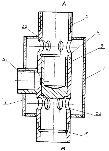
图1为本实用新型总体剖视图Fig. 1 is an overall sectional view of the utility model
图2A为本实用新型阀体正面剖视图Figure 2A is a front sectional view of the utility model valve body
图2B为本实用新型阀体的侧视图Fig. 2B is a side view of the utility model valve body
图3A为本实用新型阀套的正面剖视图Fig. 3A is the front sectional view of the utility model valve sleeve
图3B为本实用新型阀套的侧视图Figure 3B is a side view of the utility model valve sleeve
图4为本实用新型阀芯的正面剖视图Fig. 4 is the front sectional view of the valve core of the present invention
图中:1-阀套,2-阀体,21-旁通管口,22-给水孔,23-卡环槽,In the figure: 1-valve sleeve, 2-valve body, 21-bypass nozzle, 22-water supply hole, 23-snap ring groove,
3-阀芯,4-上位卡环,5-下位卡环,6-水流腔体 3-Spool, 4-Upper snap ring, 5-Lower snap ring, 6-Water flow chamber
下面结合附图和实施例作进一步说明:Below in conjunction with accompanying drawing and embodiment for further explanation:
由图1可知,本实用新型主要由阀套1,阀体2,阀芯3,上位卡环4,下位卡环5,水流腔体6组成,其中阀体2上制有旁通管口21,两组圆形给水孔22,阀体2内置有上位卡环4和下位卡环5,并装有可在上位卡环4和下位卡环5之间滑动的阀芯3,在阀体2之外装有圆柱形阀套1构成水流腔体6。As can be seen from Figure 1, the utility model is mainly composed of a valve sleeve 1, a valve body 2, a valve core 3, an upper snap ring 4, a lower snap ring 5, and a water flow chamber 6, wherein the valve body 2 is formed with a
由图可见,阀体2之外装有阀套1组成水流腔体6,该腔体可稳定水流的流速和流态便于在管路中的连续流动。It can be seen from the figure that a valve sleeve 1 is installed outside the valve body 2 to form a water flow cavity 6, which can stabilize the flow rate and flow state of the water flow and facilitate continuous flow in the pipeline.
可知本实用新型根据供水系统的具体要求确定双向单流阀的尺寸,可生产多种规格的系列产品。It can be seen that the utility model determines the size of the two-way check valve according to the specific requirements of the water supply system, and can produce series products of various specifications.
由图2A,图2B可知,阀体2是本实用新型的重要零件,它的结构由旁通管口21,两组给水孔22,两个卡环槽23组成,其中,由图2B可见两组给水孔22,每组应均匀分布在圆周上,孔的数量和尺寸大小取决于系统的流量。From Fig. 2A and Fig. 2B, it can be seen that the valve body 2 is an important part of the present utility model, and its structure is composed of a
由图3A,图3B示出,本实用新型阀套1的结构情况,它的腔体尺寸大小取决于水流的流量大小和流态。As shown in Fig. 3A and Fig. 3B, the structure of the valve sleeve 1 of the present invention, the size of its cavity depends on the flow rate and flow state of the water flow.
由图4示出,本实用新型阀芯的结构形式。Shown in Fig. 4, the structural form of the spool of the present utility model.
Claims (2)
Priority Applications (1)
| Application Number | Priority Date | Filing Date | Title |
|---|---|---|---|
| CN01225090.2U CN2491663Y (en) | 2001-06-01 | 2001-06-01 | Two-way single flow valve |
Applications Claiming Priority (1)
| Application Number | Priority Date | Filing Date | Title |
|---|---|---|---|
| CN01225090.2U CN2491663Y (en) | 2001-06-01 | 2001-06-01 | Two-way single flow valve |
Publications (1)
| Publication Number | Publication Date |
|---|---|
| CN2491663Y true CN2491663Y (en) | 2002-05-15 |
Family
ID=33641237
Family Applications (1)
| Application Number | Title | Priority Date | Filing Date |
|---|---|---|---|
| CN01225090.2U Expired - Lifetime CN2491663Y (en) | 2001-06-01 | 2001-06-01 | Two-way single flow valve |
Country Status (1)
| Country | Link |
|---|---|
| CN (1) | CN2491663Y (en) |
Cited By (1)
| Publication number | Priority date | Publication date | Assignee | Title |
|---|---|---|---|---|
| CN104515312A (en) * | 2013-09-29 | 2015-04-15 | 北京金博众科技有限公司 | Water supply and return pipe antifreezing and emptying device for solar water heating system |
-
2001
- 2001-06-01 CN CN01225090.2U patent/CN2491663Y/en not_active Expired - Lifetime
Cited By (1)
| Publication number | Priority date | Publication date | Assignee | Title |
|---|---|---|---|---|
| CN104515312A (en) * | 2013-09-29 | 2015-04-15 | 北京金博众科技有限公司 | Water supply and return pipe antifreezing and emptying device for solar water heating system |
Similar Documents
| Publication | Publication Date | Title |
|---|---|---|
| CA2366605A1 (en) | Check valve with oversized bill | |
| CN2491663Y (en) | Two-way single flow valve | |
| CN212715151U (en) | Water supply flow control system in peak period | |
| CN108180000B (en) | An automatic control anti-return one-way water injection valve | |
| CN201358963Y (en) | Novel double-direction single-flow valve | |
| CN202247785U (en) | Siphon water diversion device | |
| CN208734469U (en) | A kind of environmental protection river water intake system | |
| CN203035616U (en) | Pumping chamber for volute mixed-flow pump | |
| CN218000629U (en) | High-stability valve core for flow valve | |
| CN201159219Y (en) | Fluid conveying energy-saving device of hydraulic pump | |
| CN216171215U (en) | Hydrochloric acid absorption device for dibromomethane reaction tail gas | |
| CN204692840U (en) | A kind of pipe network connected element | |
| CN204342494U (en) | A kind of double-piston sea water desalinating plant | |
| CN201531465U (en) | Bottom valve protective device | |
| CN108413122A (en) | A kind of water hammer abatement valve, water hammer abatement pipeline and pipeline water hammer-resistant method | |
| CN219527817U (en) | Water supply system | |
| CN208670168U (en) | An automatic flow stop device for pipe internal pressure | |
| CN216810165U (en) | Convergence Node Structure of Municipal Drainage Pipe Network | |
| CN201001318Y (en) | Pressure regulating by-pass device | |
| CN219421791U (en) | Pipe-laying type irrigation device | |
| CN221237690U (en) | Active differential pressure type bypass reflux mechanism | |
| CN217184199U (en) | An energy-saving and environmentally friendly farmland water conservancy device | |
| CN207395059U (en) | A kind of novel office room waterfall | |
| CN206397817U (en) | A kind of oil-immersed pump blower inlet casing | |
| CN222357884U (en) | A pressure relief valve for blood purification |
Legal Events
| Date | Code | Title | Description |
|---|---|---|---|
| C14 | Grant of patent or utility model | ||
| GR01 | Patent grant |