CN2440407Y - foldable playpen - Google Patents
foldable playpen Download PDFInfo
- Publication number
- CN2440407Y CN2440407Y CN99240641U CN99240641U CN2440407Y CN 2440407 Y CN2440407 Y CN 2440407Y CN 99240641 U CN99240641 U CN 99240641U CN 99240641 U CN99240641 U CN 99240641U CN 2440407 Y CN2440407 Y CN 2440407Y
- Authority
- CN
- China
- Prior art keywords
- foldable playpen
- foldable
- positioning
- thread
- corner
- Prior art date
- Legal status (The legal status is an assumption and is not a legal conclusion. Google has not performed a legal analysis and makes no representation as to the accuracy of the status listed.)
- Expired - Fee Related
Links
- 230000007246 mechanism Effects 0.000 claims description 23
- 210000000078 claw Anatomy 0.000 claims description 11
- 238000005452 bending Methods 0.000 description 10
- 238000010586 diagram Methods 0.000 description 6
- 230000008878 coupling Effects 0.000 description 4
- 238000010168 coupling process Methods 0.000 description 4
- 238000005859 coupling reaction Methods 0.000 description 4
- 230000000694 effects Effects 0.000 description 3
- 230000008859 change Effects 0.000 description 2
- 239000002131 composite material Substances 0.000 description 1
- 229920001971 elastomer Polymers 0.000 description 1
- 239000000806 elastomer Substances 0.000 description 1
- 239000004744 fabric Substances 0.000 description 1
- 239000000463 material Substances 0.000 description 1
- 238000000034 method Methods 0.000 description 1
- 238000012986 modification Methods 0.000 description 1
- 230000004048 modification Effects 0.000 description 1
Images


Classifications
-
- A—HUMAN NECESSITIES
- A47—FURNITURE; DOMESTIC ARTICLES OR APPLIANCES; COFFEE MILLS; SPICE MILLS; SUCTION CLEANERS IN GENERAL
- A47D—FURNITURE SPECIALLY ADAPTED FOR CHILDREN
- A47D13/00—Other nursery furniture
- A47D13/06—Children's play- pens
- A47D13/061—Children's play- pens foldable
- A47D13/063—Children's play- pens foldable with soft walls
Landscapes
- Mutual Connection Of Rods And Tubes (AREA)
Abstract
Description
本实用新型涉及一种折叠式游戏围栏,特别是一种可在不使用时,将其高度缩减,使占用的材积更小,收藏更方便的游戏围栏。The utility model relates to a foldable playpen, in particular to a playpen whose height can be reduced when not in use, so that the occupied volume is smaller and the playpen is more convenient for storage.
游戏围栏是一种提供婴幼儿游憩时的活动空间。于美国专利第4811437号专利案、第4985948号专利案。第5163191号专利案、第5697111号专利案及第5727465号专利案中即揭示了各种针对游戏围栏(Plavyard)所做的相关设计,其中在第4811437号专利案、第5697111号专利案及第5727265号专利案更揭示了一种折叠式游戏围栏结构,此种折叠式游戏围栏在使用时可改变其支撑架之形状而呈现展开状态或收折状态。The playpen is an activity space that provides an activity space for infants and young children to play. In US Patent No. 4,811,437 and No. 4,985,948. In the No. 5163191 patent case, the No. 5697111 patent case and the No. 5727465 patent case, various related designs for the game fence (Plavyard) are disclosed, among which in the No. 4811437 patent case, the No. No. 5,727,265 patent further discloses a foldable playpen structure, which can change the shape of its support frame to present an unfolded or folded state when in use.
如r第1、2图]所示之传统折叠式游戏围栏构造,从图中可以见悉该游戏围栏基本上是由一支撑架及一包覆于该支撑架上之软质织类布垫所组成,其中支撑架由上、下层框架,以及复数支边角支架组接而成;为了节省收藏时所占用的材积,以往的设计皆会在上、下层框架上设有可令其折叠收合之弯折机构,该上、下层框架可以藉著弯折机构将对应折收,缩减其所占用的面积(如第3图所示);不过,就整个支撑架而言,支撑架虽可利用上、下且层框架弯折来达到缩减长度及宽度的功效,但是支撑架的高度仍然维持不变,致使支撑架站立收藏时所占用的高度或是躺平摆放时所需的长度仍然无法缩减,所以就收折的问题而言,传统的游戏围栏仍存在以上之问题点。The structure of the traditional foldable playpen as shown in Figures 1 and 2], it can be seen from the figure that the playpen is basically composed of a support frame and a soft woven cloth pad wrapped on the support frame The support frame is composed of the upper and lower frames, and a plurality of corner brackets; in order to save the volume occupied by the collection, the previous design will have a folding and collapsible structure on the upper and lower frames. The bending mechanism, the upper and lower frames can be folded correspondingly by the bending mechanism, reducing the occupied area (as shown in Figure 3); however, as far as the entire support frame is concerned, although the support frame can be used The upper and lower frames are bent to achieve the effect of reducing the length and width, but the height of the support frame remains unchanged, so that the height occupied by the support frame when it is standing and stored or the length required for lying flat is still insufficient. Therefore, as far as the folding problem is concerned, the traditional playpen still has the above problems.
有签于上述之问题点,本实用新型之主要目的即为提供一种可以解决前述游戏围栏于收藏时,针对高度无法有效缩小的改良设计,使其收藏时所占用的材积更小。In view of the above-mentioned problems, the main purpose of this utility model is to provide an improved design that can solve the problem that the height of the aforementioned playpen cannot be effectively reduced during storage, so that it occupies a smaller volume during storage.
为达到上述目的,本实用新型折叠式游戏围栏,具有一可介于展开状态及收折状态之支撑架,该支撑架包括有:In order to achieve the above purpose, the folding playpen of the present invention has a support frame that can be between the unfolded state and the folded state. The support frame includes:
上、下层框架,该上、下层框架由复数支架、复数个令该支架彼此结合之角连接件所构成;Upper and lower frames, the upper and lower frames are composed of a plurality of brackets and a plurality of corner connectors that connect the brackets to each other;
复数支角边支架,该角边支架由彼此套接并可轴向相对伸缩之内、外管体组成,该角边支架两端分别与该上、下层框架对应之该角连接件相接连;A plurality of corner side brackets, the corner side brackets are composed of inner and outer pipe bodies that are socketed with each other and can be relatively stretched axially, and the two ends of the corner side brackets are respectively connected with the corresponding corner connectors of the upper and lower frames;
一定位机构,该定位机构结合于该角边支架上。A positioning mechanism, the positioning mechanism is combined with the corner bracket.
前述折叠式游戏围栏之定位机构包括有一用以固定该内、外管体相对位置的卡掣件,以及一用以解除该卡掣件对该内、外管体的限制,令该内外管体得以相对伸缩之释放件。The positioning mechanism of the aforesaid foldable playpen includes a catch member for fixing the relative position of the inner and outer pipe bodies, and a catch member for removing the restriction of the catch member to the inner and outer pipe bodies, so that the inner and outer pipe bodies A relatively stretchable release piece.
前述折叠式游戏围栏之卡掣件由一被安置于该内管体中的弹片,以及设置于该弹片上之定位凸点构成,该定位凸点同时穿过该内、外管体。The catch piece of the aforementioned foldable playpen is composed of an elastic piece arranged in the inner tube body and a positioning convex point arranged on the elastic piece, and the positioning convex point passes through the inner and outer tube bodies at the same time.
前述折叠式游戏围栏之内、外管体上设有可供该定位凸点顶出之轴孔及定位孔。A shaft hole and a positioning hole for the positioning convex point to be ejected are provided on the inner and outer tube body of the aforementioned foldable playpen.
前述折叠式游戏围栏之释放件由一个弹性体,以及形成于弹性体两端内缘,恰好抵顶于该槽孔之顶块所构成。The release part of the aforementioned foldable playpen is composed of an elastic body and a top block formed on the inner edges of both ends of the elastic body, which just abuts against the slot hole.
前述折叠式游戏围栏之定位机构包括有一结合于该外管体上之收合部,以及一用以迫使该收合部夹合于该内管体之闭锁件。The positioning mechanism of the above-mentioned foldable playpen includes a retractable part combined with the outer tube body, and a locking part for forcing the retractable part to be clamped to the inner tube body.
前述折叠式游戏围栏之收合部由外缘形成有螺纹之复数爪片所构成,且相邻的两爪片之间形成有一道缺口;又该闭锁件具有一可螺合于收合部上之锥形螺孔。The folding part of the folding playpen is composed of a plurality of claws with threads formed on the outer edge, and a gap is formed between two adjacent claws; The tapered screw hole.
前述折叠式游戏围栏之螺纹为复线螺纹。前述折叠式游戏围栏之螺纹为三线螺纹。The threads of the aforementioned foldable playpen are double thread threads. The thread of the aforementioned folding playpen is a three-thread thread.
本实用新型折叠式游戏围栏,特别在其支撑架中,用以组架于上、下层框架,而直立结合于上、下层框架角落的支角边架设计成可伸缩式之构造,藉此以令角边支架可在使用时,将其拉伸伸长,或是经由收合,缩短其长度,使支撑架的高度缩短,该占用的材积更小,收藏更为方便。The folding play fence of the utility model, especially in its supporting frame, is used to set up the frame on the upper and lower frames, and the corner frame which is upright and combined with the corners of the upper and lower frame is designed as a telescopic structure, thereby When the corner bracket is in use, it can be stretched and extended, or its length can be shortened by being folded, so that the height of the support frame is shortened, and the occupied volume is smaller, making storage more convenient.
有关本实用新型之详细说明及技术内容,现配合图式说明如下:The detailed description and technical content of the present utility model are described as follows in conjunction with the drawings:
图式说明:Graphic description:
第1图,为习知游戏围栏之立体外观示意图;Figure 1 is a schematic diagram of a three-dimensional appearance of a conventional playpen;
第2图,为习知游戏围栏之支撑架于展开状态之构示意图;Figure 2 is a schematic diagram of the structure of the support frame of the conventional playpen in the unfolded state;
第3图,为习知游戏围栏之支撑架于收折状态之构造示意图;Figure 3 is a schematic diagram of the structure of the support frame of the conventional playpen in the folded state;
第4图,为本实用新型之立体示意图;Fig. 4 is a three-dimensional schematic diagram of the utility model;
第5图,为本实用新型角边支架之分解示意图;Fig. 5 is an exploded schematic view of the corner bracket of the present invention;
第6A、6B图,为第4图于Ⅵ-Ⅵ位置之剖面示意图,暨其使用状态;Figures 6A and 6B are schematic cross-sectional views at the position VI-VI of Figure 4, and their usage status;
第7图,为本实用新型另一状态之立体示意图,显示角边支架经伸缩固定在一收合长度;Figure 7 is a three-dimensional schematic diagram of another state of the present invention, showing that the corner bracket is fixed at a retracted length by telescopic expansion;
第8图,为本实用新型上层框架之另一实施态样;Fig. 8 is another embodiment of the upper frame of the present utility model;
第9图,为第8图上层框架之收合状态示意图;Figure 9 is a schematic diagram of the collapsed state of the upper frame in Figure 8;
第10A、10B图,为本实用新型定位机构之实施例剖面示意图。Figures 10A and 10B are schematic cross-sectional views of embodiments of the positioning mechanism of the present invention.
实施例:Example:
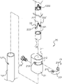
请同时参阅r第4图],图中揭示一种折叠式游戏围栏之支撑架10构造,如图所示,支撑架10由上、下层框架11,12以及复数支角边支架13,13’组构而成,其中,上、下层框架11,12由复数支架111,112,121,122、复数个用以将支架111,112,121,122彼此结合之角连接件113,123组接而成;而角边支架13,13’分别立设组接于上、下层框架11,12对应之角连接件113,123,使上、下层框架11,12与角边支架13,13’形成一个复合式矩形框架;Please also refer to Fig. 4 at the same time], the structure of a
上、下层框架11,12分别设有弯折机构114,124,此弯折机构114,124可使该支架横向伸展成一直线,或是经由弯折,相对枢转内弯而收合,改变支撑架的长度或宽度;由于弯折机构114,124为一般习知技艺,且能约达成令支架111,112,121,122达到弯折功能的结构形态繁多,故在此即不多赘述。The upper and
相较于传统构造,本实用新型主要强调的是在于角边支架13上所做的改良,由图中可以见悉,其中角边支架13两端分别接连于上、下层框架11,12对应之角连接件113,123上,提供撑抵上层框架11的功效;又、角边支架I3由彼此套接,并可轴向相对伸缩之内、外管体131,132组成,亚于每一角边支架13上配置有一个可以使角边支架13调整其长度,而将角边支架13固定在一伸展长度及一收合长度上的定位机构20。Compared with the traditional structure, the utility model mainly emphasizes the improvements made on the
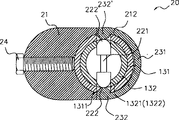
请配合参阅r第5、6 A、6 B图],定位机构20指一种可以该角边支架13调整其长度,且可固定角边支架13调整后之长度的构造,根据本实用新型所揭之实施例显示,定位机构20可以是由一结合件21,卡掣件22,以及一配置于结合件21上之释放件23所组成;如图所示,卡掣件22由一被安置于内管体132中弹片221,以及设置于弹片221末端处外侧,受到弹片221张力推顶之定位凸点222,222,此定位凸点222,222’可同时穿过内、外管体131,132,令内、外管体132,131彼此之相对位置固定;为使前达卡掣件22上的定位凸点222,222’能钧同时穿设过内、外管体132,131,于实施上,内、外管体132,131上匹配设有可供定位凸点222,22T顶出之定位孔1321,1322及轴孔1311。Please refer to r No. 5, 6 A, 6 B Figures], the
前述之结合件21则是一个可固定于外管体131上之构件,于结合件ZI上设有一可套置于外管体131外缘之穿孔211,可藉由穿孔211套置至外管体131上之预定位置后,再以螺栓24迫使其与外管体131相结合;于结合件21外缘益具有一嵌槽212,且在嵌槽212上设有与4轴孔1311对应之槽孔213,213’;而释放件23则是由一个可嵌合于嵌槽212上之弹性体231,以及形成于弹性体231两端内缘,恰好对应于槽孔213,213’之顶块232,232’所构成,顶块232,232’可穿过槽孔213,213’,并且与定位凸点222,222’相互抵顶;于常态上,顶块232,232,受到定位凸点222,222’的推顶作用,使顶块232,232,仅伸及至槽孔213,213’中,该内、外管体132,131可经由定位凸点222,222’的限制,而无法相对位伸缩位移;不过一旦弹性体231之两侧经受到外侧力量而向内压合时,顶块232,232’则会迫使定位凸点222,222,向内退移,使定位凸点222,222’退移出轴孔213,213,进而令内、外管体132,131得以相对伸缩位移。The
藉此之构成,为了使角边支架13可依支撑架10的使用状态,藉由内、外管体132,131经伸缩而固定在一伸展长度(如第4图所示)或是一收合长度(如第7图所示)的状态下,因此在内管体132上至少要设有二个卡掣件22,22’,此二掣件22’的设置位置恰好是在内、外管体131,132经伸缩而伸展至最长的状态,以及在最短的状态时,定位凸点222,222’恰好能构对应到轴孔213,213’,该定位凸点222,222’嵌入轴孔213,213’中,使内、外管体132,131之相对位置固定。With this structure, in order to make the
本实用新型的实用新型特点虽然著重于角边支架13是一个可以依使用状态而调整长度的设计;虽然上层框架11虽非为本实用新型创新之处,但是就整体实施上,为了强调其占用的材积能构更小,因此如r第4、7图]中所示之上层框架11,由于其仅有在二对应之支架111上配置有弯折机构114,致使上层框架11仅能收折一个方向的长度而已;是以,本实用新型于实施上,当然也可再于另一方向对应、设置之二支架112亦匹配设置有一弯折机构114’(如第8、9图所示),使整体收折时,上层框架11可更加缩小,更节省收藏空间。Although the utility model features of the present utility model focus on that the
请参阅r第10A、10B图],由上述之说明可以知道,定位机构20主要即是提供一种可以使内、外管体131,132固定在一伸展长度及一收合长度的构造。不过,就可实施的范畴,除了前述所揭之构造外,亦可探以如下说明之手段;如图所示,定位机构20可以是包括有一结合于外管体131一端端缘之收合部25,以及一迫使收合部25夹合于内管体131之闭锁件26;其中收合部25由复数片自外管体132延伸出,且外缘形成有螺纹251之爪片252,252’所构成,且相邻的两爪片252,252’之间皆形成有一道缺口253;而前述之闭锁件26则是在轴向形成有一可螺合于收合部25上之锥形螺孔261;藉此之构成,当闭锁件26螺合于收合部25外缘的螺纹251深度越深,爪片252,252’会因锥形螺孔261的口径越来越小而被迫内缩,使爪片252,252’内面与内管体131之外表面发生接触磨擦力,使内管体131遭致磨擦阻力的制动而无法相对于外管体132作伸缩运动;除非是闭锁件26退移出螺纹251后,该爪片252,252’利用材料本身回复弹性,使爪片252,252’内壁面与内管体131的表面接触力减少,或是完全消失之后,内、外管体132才能再相对运动,变角边支架13的长度。Please refer to Figs. 10A and 10B], it can be known from the above description that the
附加说明一点,于前揭之实施例中,螺纹251可采以复线螺纹或是三线螺纹的设计,使闭锁件26能构相对于收合部25达到快速闭锁及退出的功效。As an additional note, in the above disclosed embodiments, the
以上所述,仅为本实用新型之较佳实施例而已,并非用来限定本实用新型实施之范围。即凡依本实用新型申请专利范围所做的均等变化与修饰,皆为本实用新型专利范围所涵盖。The above descriptions are only preferred embodiments of the present utility model, and are not intended to limit the implementation scope of the present utility model. That is, all equivalent changes and modifications made according to the patent scope of the utility model are covered by the patent scope of the utility model.
图式符号说明:Explanation of schematic symbols:
支撑架10
上层框架11
支架111,112,121,122Brackets 111, 112, 121, 122
角连接件113,123Corner connectors 113,123
下层框架12
弯折机构114,114,124Bending mechanism 114,114,124
角边支架13,13’
内管体131
外管体132
定位孔1311,1312
轴孔1321
定位机构20
结合件21
穿孔211piercing 211
嵌槽212
槽孔213,213’Slot 213,213'
卡掣件22,22’
弹片221
定位凸点222,222’,Locating bumps 222,222',
释放件23
弹性体231
顶块232,232’,Top block 232,232’,
螺栓24
收合部25
螺纹251
爪片252,252’,claw piece 252,252',
缺口253
止滑片254Anti-slip sheet 254
闭锁件26
锥形螺孔261
Claims (9)
Priority Applications (1)
| Application Number | Priority Date | Filing Date | Title |
|---|---|---|---|
| CN99240641U CN2440407Y (en) | 1999-11-01 | 1999-11-01 | foldable playpen |
Applications Claiming Priority (1)
| Application Number | Priority Date | Filing Date | Title |
|---|---|---|---|
| CN99240641U CN2440407Y (en) | 1999-11-01 | 1999-11-01 | foldable playpen |
Publications (1)
| Publication Number | Publication Date |
|---|---|
| CN2440407Y true CN2440407Y (en) | 2001-08-01 |
Family
ID=34027648
Family Applications (1)
| Application Number | Title | Priority Date | Filing Date |
|---|---|---|---|
| CN99240641U Expired - Fee Related CN2440407Y (en) | 1999-11-01 | 1999-11-01 | foldable playpen |
Country Status (1)
| Country | Link |
|---|---|
| CN (1) | CN2440407Y (en) |
Cited By (1)
| Publication number | Priority date | Publication date | Assignee | Title |
|---|---|---|---|---|
| CN102068158A (en) * | 2011-01-05 | 2011-05-25 | 好孩子儿童用品有限公司 | Game enclosure |
-
1999
- 1999-11-01 CN CN99240641U patent/CN2440407Y/en not_active Expired - Fee Related
Cited By (2)
| Publication number | Priority date | Publication date | Assignee | Title |
|---|---|---|---|---|
| CN102068158A (en) * | 2011-01-05 | 2011-05-25 | 好孩子儿童用品有限公司 | Game enclosure |
| CN102068158B (en) * | 2011-01-05 | 2013-08-07 | 好孩子儿童用品有限公司 | Game enclosure |
Similar Documents
| Publication | Publication Date | Title |
|---|---|---|
| CN1244762C (en) | Tripod | |
| CN2696950Y (en) | Collapsible toddler frame | |
| CN1272083C (en) | Foldable ping-pong table | |
| US20140174491A1 (en) | Tent Skeleton and Tent | |
| CN1369250A (en) | Extension tube of vacuum duster | |
| US7958578B2 (en) | Play yard | |
| CN2723753Y (en) | Folding joints for baby nets | |
| CN1448088A (en) | folding banquet table | |
| WO2009129680A1 (en) | A lambdoidal ladder | |
| CN1596859A (en) | Wheelchair useable as walking stick | |
| CN2440407Y (en) | foldable playpen | |
| US6725475B1 (en) | Foldable mechanism for a base of playyard | |
| US9668586B2 (en) | Camp bed frame and camp bed | |
| CN2376818Y (en) | Crib bottom joint with locking action | |
| CN218738147U (en) | Folding structure of baby bedstead | |
| CN103671476A (en) | Rotating joint and game surrounding bed with rotating joint | |
| CN2393770Y (en) | Telescopic luggage trolley | |
| CN2822388Y (en) | Height-adjustable changing table unit and crib with same | |
| CN2819888Y (en) | Rod structure in flat umbrella | |
| CN2778632Y (en) | Trolley retractable structure | |
| CN216973233U (en) | Portable folding warning fence | |
| CN214616338U (en) | Anti-shaking connecting structure of telescopic ladder | |
| CN2170681Y (en) | Deforming table | |
| CN223362812U (en) | A portable guitar | |
| CN218008970U (en) | Telescopic stool |
Legal Events
| Date | Code | Title | Description |
|---|---|---|---|
| C14 | Grant of patent or utility model | ||
| GR01 | Patent grant | ||
| C19 | Lapse of patent right due to non-payment of the annual fee | ||
| CF01 | Termination of patent right due to non-payment of annual fee |