CN2324748Y - Light-projector - Google Patents
Light-projector Download PDFInfo
- Publication number
- CN2324748Y CN2324748Y CN97290002U CN97290002U CN2324748Y CN 2324748 Y CN2324748 Y CN 2324748Y CN 97290002 U CN97290002 U CN 97290002U CN 97290002 U CN97290002 U CN 97290002U CN 2324748 Y CN2324748 Y CN 2324748Y
- Authority
- CN
- China
- Prior art keywords
- light
- face
- emitting
- emitting face
- emitting device
- Prior art date
- Legal status (The legal status is an assumption and is not a legal conclusion. Google has not performed a legal analysis and makes no representation as to the accuracy of the status listed.)
- Expired - Lifetime
Links
Images


Classifications
-
- G—PHYSICS
- G02—OPTICS
- G02B—OPTICAL ELEMENTS, SYSTEMS OR APPARATUS
- G02B6/00—Light guides; Structural details of arrangements comprising light guides and other optical elements, e.g. couplings
- G02B6/0001—Light guides; Structural details of arrangements comprising light guides and other optical elements, e.g. couplings specially adapted for lighting devices or systems
- G02B6/0011—Light guides; Structural details of arrangements comprising light guides and other optical elements, e.g. couplings specially adapted for lighting devices or systems the light guides being planar or of plate-like form
- G02B6/0013—Means for improving the coupling-in of light from the light source into the light guide
- G02B6/0015—Means for improving the coupling-in of light from the light source into the light guide provided on the surface of the light guide or in the bulk of it
- G02B6/0018—Redirecting means on the surface of the light guide
-
- G—PHYSICS
- G02—OPTICS
- G02B—OPTICAL ELEMENTS, SYSTEMS OR APPARATUS
- G02B6/00—Light guides; Structural details of arrangements comprising light guides and other optical elements, e.g. couplings
- G02B6/0001—Light guides; Structural details of arrangements comprising light guides and other optical elements, e.g. couplings specially adapted for lighting devices or systems
- G02B6/0011—Light guides; Structural details of arrangements comprising light guides and other optical elements, e.g. couplings specially adapted for lighting devices or systems the light guides being planar or of plate-like form
- G02B6/0013—Means for improving the coupling-in of light from the light source into the light guide
- G02B6/0015—Means for improving the coupling-in of light from the light source into the light guide provided on the surface of the light guide or in the bulk of it
- G02B6/002—Means for improving the coupling-in of light from the light source into the light guide provided on the surface of the light guide or in the bulk of it by shaping at least a portion of the light guide, e.g. with collimating, focussing or diverging surfaces
- G02B6/0021—Means for improving the coupling-in of light from the light source into the light guide provided on the surface of the light guide or in the bulk of it by shaping at least a portion of the light guide, e.g. with collimating, focussing or diverging surfaces for housing at least a part of the light source, e.g. by forming holes or recesses
Landscapes
- Physics & Mathematics (AREA)
- General Physics & Mathematics (AREA)
- Optics & Photonics (AREA)
- Illuminated Signs And Luminous Advertising (AREA)
- Control Of Indicators Other Than Cathode Ray Tubes (AREA)
- Non-Portable Lighting Devices Or Systems Thereof (AREA)
- Devices For Indicating Variable Information By Combining Individual Elements (AREA)
- Controls And Circuits For Display Device (AREA)
Abstract
The utility model relates to a light-projector, which is composed of a body composed of the transparent material, one light source or a plurality of light sources for emitting the light into the body and a light emitting face which is positioned on one side of the body or a plurality of sides of the body. The light emitted into the body through the emitting face is emitted out of the body. A ribbon-shaped light source is arranged on one side to make the emitting light emitted through the ribbon-shaped light source which faces to the body basically enter the body completely. At least the part of one side of the body forms a reflector of the light which is emitted into the body. The reflector at least reflects the light which is emitted on the reflector to the light emitting face partially. Consequently, the utility model can realize the optimal efficiency of light and the uniform irradiation of the light emitting face.
Description
The present invention relates to a kind of light-emitting device.This light-emitting device is especially in outdoor advertising, emergency lighting, photoconduction is applied to aspects such as system and indicated numbers, it has a body that is made of transparent material, one or more light is incided light source and a light-emitting face that is positioned at body one side in the body, incide light in the body by outgoing in the body by this light-emitting face, what wherein have a band shape at least vertically is that base company's supervention send the light source of light directly to be arranged on the body or in the body with it, should make by the light towards the band light source side outgoing of body to enter substantially fully in the body, they are usually by the neon tube that bends to stroke to be shown, the illuminator assembly of known way or independent illuminator constitute.The very expensive and subject to damage of this luminous advertisement.
Task of the present invention is to propose a kind of light-emitting device, and this light-emitting device manufacturing expense is cheap, do not have framework and be not subjected to the influence of shape, the light that gone out by light emitted of subject to damage and can utilizing best not too.
Task of the present invention is solved by the light-emitting device of following characteristics: the side of body part at least is formed on internal radiation reflection of light mirror or reverberator, this catoptron reflexes to light-emitting face at least in part with light incident thereon, wherein form a wall section as crooked catoptron in a rib scope of body, this wall section will reflex to light-emitting face by the light that band light source directly projects on it.Owing to can adopt such as the plastic material of shock resistance such as acrylic plastic glazing or anti-fracture as the material of light-emitting device body and can change power supply at an easy rate, so light-emitting device of the present invention has the life-span of the letter length that constitutes than the neon tube that adopts in outdoor advertising.Can also adopt low-tension supply in addition, thereby than the luminescent device power saving of neon tube system.
First embodiment of the invention, whole body can be formed with the shape of character to be shown, sign, pattern or stroke to be shown, and wherein band light source preferably is arranged on the side and extends by the profile of character, luminophor or stroke.Light-emitting face can have the shape of character to be shown or stroke simultaneously.Be arranged on the body according to the second embodiment light source, make and on a part of light-emitting face, demonstrate character to be shown or stroke.Character to be shown for this reason can form on body with relief shape, preferably on light-emitting face or with the retrography form at dorsal part.In first scheme of this embodiment, the following female type of character forms and is provided with one or more band light source in consequent groove.In alternative plan, letter or stroke are convexs, thereby are enclosed by the grooved ring around.In groove, be provided with one or more band light source.Light source in this embedded body can be touched or be cast in the groove by corresponding groove by a side of body.Can certainly manufacture this light-emitting device that has the light source of casting in the following way, with light source be placed on a kind of and above-mentioned in groove configuration conform in the mold of structure, then body is cast in around the light source.If body itself is formed the character to be shown or the shape of stroke to be shown, then usually can be with band light source in smooth mode or be arranged in the groove on side or be arranged on the level and smooth side of body.But also can strike up partnership light source by casting and body.
The light-emitting face material of body can be transparent or diffuse scattering (" frosted glass ") and also can be coloured in case of necessity according to using.For the wide part that makes radiation is all aimed at reflecting surface, can light source be installed with certain inclination angle.Can adopt such as the spraying plating reflecting material, paste the Cheng Jing that prior art such as reflectance coating realizes face as the formation of the side of the body of catoptron.Owing to when light hits the interface, can reflect certain light component, also can realize mirror effect by polishing to respective face.This face so should be provided with, make by the most light to the light-emitting face reflection to be reflected with in the light of suitable direction incident.
According to the present invention, because it is comparatively even to adopt band light source to relate to the light output of strip of light direction, the face as mirror structure constitutes imaginary light source simultaneously, thereby makes light-emitting face by opposite side and thereby shone more equably.Body can have a plurality of faces as mirror structure, and wherein mirror effect is relevant with the light of radiation in vivo, and promptly the light of radiation is reflected on reflecting surface in the ex vivo in vivo.
Band light source only gives off a spot of light component in narrow side, and simultaneously minute surface has reduced the absorption on light absorbing of body by the orienting reflex to light-emitting face, thereby has improved overall optical efficiency.Wherein minute surface carries out the suitable guiding to light-emitting face to light beam, and this light beam is directly from light source or one non-irreflexive.
A wall of body should be for example by becoming mirror to constitute concave mirror or convex lens and will reflecting to light-emitting face from the light of light source or another minute surface, thereby the light that makes reflection covers the section of the light-emitting face of a crooked and directed decision specific, that pass through this wall section, and this section can certainly be the overall optical exit facet.Both the radiation cone broadening can be able to be narrowed down again by reflection simultaneously.
Can replenish or the change of alternative formula ground above-mentioned configuration, make to have at least the light that a part incides on the crooked wall spare to pass through second, preferred flat direct reflection is to light-emitting face.
Can adopt the light output on the dual mode realization light-emitting face.
Band light source can so be set and to the interface of the body of internal reflection, the light that makes radiation in vivo is with greater than angle of total reflection α
TAngle incide on the light-emitting face.Light only has the position outgoing of uneven surface at light-emitting face, although this is that local incident angle can be less than the angle of total reflection because on average incident angle is greater than the angle of total reflection herein.Light-scattering material or film realization can be ground or cover in this surface heterogeneous in a known way by burn into.
In addition, also light source and reflecting surface can be set so, make light to small part project light-emitting face, thereby make it by the outgoing of the inner branch of body with angle less than the angle of total reflection by its radiation or reflection.But owing to there is the light of certain component to be reflected in the ex vivo, so a parallel reflecting surface should be set on the light-emitting face opposite, this reflecting surface cooperates with other reflecting surface in the body in case of necessity with the light light echo exit facet that leads again.
When specific application, directly the light from light source might be disadvantageous by the light-emitting face outgoing.When band light source is made of a plurality of independent light sources and too little to the distance of light-emitting face by light source, so that the light cone of each independent light source is can overlap on light-emitting face the time, especially like this.When these situations, can light source be set so by corresponding orientation or common light velocity limitation arrangement, make by its light that gives off and arrive light-emitting face without in advance reflection, project herein with angle greater than the angle of total reflection.
Light-emitting device of the present invention has a solid body, and this body especially also can be made of the plastics that are easy to be shaped and process.So also can make the complicated shape of this body.
On the one hand, can adopt banded circuit board, adopt surface mount (SMD) technology that light emitting diode is being covered on circuit board, realize sealing, firm effect as band light source.On the other hand, also have the band light source of being made by electroluminescent membrane, this band light source is luminous continuously on its length, and for example at United States Patent (USP) 5,845, the trade name described in 752 is the known materials of super new neon (SNN).
Relevant further feature and advantage of the present invention please contrast accompanying drawing referring to following detailed explanation.
Fig. 1 first embodiment of the present invention;
The cross-sectional view of first kind of scheme of Fig. 2 first embodiment of the present invention;
The cross-sectional view of second kind of scheme of Fig. 3 first embodiment of the present invention;
The cross-sectional view of the third scheme of Fig. 4 first embodiment of the present invention;
The partial cross section figure of light path in third party's case of Fig. 5 a and 5b first embodiment of the present invention;
Fig. 6 a-6j is used to hold the various designs of the groove of band light source;
The various configurations of Fig. 7 a-7d band light source in the body groove;
The front view of Fig. 8 second embodiment of the present invention;
The rear view and the partial section of first kind of remodeling of Fig. 9 a-9b second embodiment of the present invention;
The rear view and the partial section of second kind of scheme of Figure 10 a-10b second embodiment of the present invention.
In following explanation, will be indicated with the device identical or that function is identical of identical Reference numeral to light-emitting device of the present invention.Adopt the dotted line parallel to represent to reflecting surface with line.
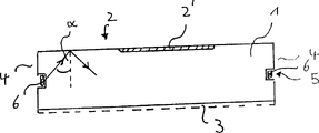
First embodiment of the light-emitting device of the present invention of luminous letter shown in Figure 1 (W) shape.Simultaneously, the view of Fig. 2 is perpendicular to alphabetical dotted line, for example along the sectional view of the line I-I that marks among Fig. 1.
Light-emitting device is mainly by the material of transparent, shock resistance and fracture.For example the body of acryl resin organic glass formation constitutes, and this material can be transparent or translucent.This body has two flat interfaces that are parallel to each other 2 and 3, and these two interfaces are linked together by sidewall 4.On sidewall, for example adopt cut or mill and low-voltage light source 6 that follow-up polishing forms transparent groove 5, one band shapes stretches in this groove.This light source for example can be electroluminescent membrane (for example SNN) system band spare and preferred on the side or its dorsal part have the connector of power supply (not shown).Groove 5 stretches also preferably around whole letter along the side with band light source 6 is vertical with the cross section.Because light source 6 embeds in the transparent groove, thereby can realize that all effective luminous powers can enter in the body 1 substantially.
And the light-emitting face of 2 constituting bodies also can have one mao of sand section 2.The face 3 relative with exit facet 2 is to internal reflection, thereby the light that face 3 will be propagated in body 1 reflexes to light-emitting face 2.
The light of being launched by light source 6 partly projects reflecting surface 3 and part projects on the light-emitting face 2.As long as incident angle α is greater than angle of total reflection α
T, the outgoing intensity that then projects the light of light-emitting face 2 is
I
T=I
O.sIn
2(α-α
T) and reflection strength be
I
R=I
O.COS
2(C-α
T), I wherein
OBe incident intensity.With greater than angle of total reflection α
TThe incident angle α light that projects light-emitting face will all be reflected.
The light directive reflecting surface 3 that is reflected on light-emitting face 2, this reflecting surface will be with directly to project the light of reflecting surface by light source 6 identical, this light back reflection to light-emitting face 2.
Between two parallel faces, carry out reflex time, remain unchanged in the incident angle on a face under the situation of continuous reflection.In order to realize inciding greater than the angle of the angle of total reflection outgoing of component of the light of light-emitting face 2 with when beginning, can make change to the embodiment shown in Fig. 1, reflecting surface 3 tilts corresponding to light-emitting face, thereby changes carrying out the incident angle of reflex time on light-emitting face 2 repeatedly.But also can by as among Fig. 1 with 2 ' the hair sand section realization light outgoing that indicates, wherein Biao Mian orientation changes all the time, thus make average orientation with light-emitting face 2 be the incident angle of benchmark greater than the angle of total reflection, and the incident angle of part is less than the angle of total reflection.Also can pass through simultaneously to the diffusion coating of light-emitting face 2 or by adopting diffusion material to realize identical effect body 1.Light-emitting face 2 is used a kind of diffusion fully in a preferred implementation of the present invention, and colored in case of necessity film covers.
In the embodiment that has parallel surface 2 and 3 of Fig. 2, the device of a restriction light can be set, shadow shield for example, the effect of this device is, make the light launched by light source 6 in light-emitting face 2 and the incident angle on reflecting surface 3 greater than the angle of total reflection.When this situation, light can only be in diffuser 2 ' ejaculation, and light is reflected fully in all the other scopes of light-emitting face 2.
Sectional view in the various schemes of luminous letter shown in Fig. 1 shown in Fig. 3 to Fig. 5.
Except that reflecting surface 3, sidewall 14a and 14b reflect equally and are obliquely installed with respect to exit facet 2 and reflecting surface 3 in the scheme of Fig. 1 embodiment shown in Fig. 3.Warp is to the corresponding selection of light-emitting face 2 and reflecting surface 3 angle betas and the γ of side 14a, 14b and standard, the light that projects light-emitting face 2 with the angle greater than the angle of total reflection during beginning projects on the light-emitting face 2 with an angle through the one or many reflection at sidewall 14a, 14b, and this angle is less than the angle of total reflection.Owing to have reflecting wall 14a, 14b in the both sides of body, so light can carry out repeatedly coming and going in vivo, wherein under to angle beta, the corresponding selected situation of γ, the incident angle on light-emitting face when round at every turn all is different.
As described above with reference to Figure 2 only when the hair sand section glazing outgoing of light-emitting face 2, the angle between two sidewall 14a and 14b is selected 90 ° for use, thereby the light direction former with it after primary event returned abreast.The angle beta of choosing in addition always incides on the light-emitting face 2 with the angle greater than the angle of total reflection thereby make at the light that reflects on the face 14a greater than the angle of total reflection.The setting of last light source 6 should make reflecting wall 14a and 14b play a part shadow shield, and this shadow shield will stop light to be directly incident on light-emitting face with the angle less than the angle of total reflection.In this embodiment, as long as face 3 is parallel with light-emitting face 2, face 3 just needn't become mirror reflection, though this be because of at this face glazed thread also with angle incident greater than the angle of total reflection.
In the remodeling of first embodiment shown in Figure 4, face 3 and the sidewall 24a relative with light-emitting face 2; 24b reflects.And sidewall has wall section 25a and 25b as light-radiating lens in the rib scope, and the effect of this wall section is, the light that incides the rib scope directly reflexed to light-emitting face 2 and reflecting surface 3 and it is distributed on the specific face scope.In Fig. 5 a and the 5b example of passing the imperial examinations at the provincial level corresponding light path is shown.
Fig. 5 a illustrates the mode of action of the wall section 25a of reflection.Incide the light beam S of wall section 25 by light source 6
1By wall section 25a reflection and broadening, thereby in fact overall optical exit facet 2 is capped.Be reflected on the light-emitting face 2 by wall spare 25a at the light that is reflected on the face 3 with big reflection angle equally.Light beam S
1The broadening degree depend on the curvature of wall spare 25a.In corresponding big radius of curvature R
1With incident scope circle of curvature P
1Central point under the situation of relevant position, light beam S
1Only cover a part of exit facet, this is to being useful when the particular range that must the intensive irradiation light-emitting face.
The mode of action of the 25b of reflecting wall section shown in Fig. 5 b.Light beam S from light source
2By wall section 25b reflection, thereby make it broadened and cover entire emission face 3 substantially.Face 3 reflexes to light-emitting face with the part in this light then.Can be to radius of curvature R
2With corresponding circle of curvature P
2Central point so select, make light beam S
2Fall in certain section of face 3, reflexed to fully on the light-emitting face 2 at this section light beam.In addition, wall spare 25b will reflex on the face 3 at the light that is reflected with big angle on the light-emitting face 2.
When adopting symmetrical structure shown in Figure 4, four reflecting segment 25a, the bendings of 25b circular also have identical radius-of-curvature.
Two band light source are oppositely arranged in the embodiment of the light-emitting device of the present invention shown in Fig. 2 to 5.But substitute this scheme also only the side in both sides adopt a light source and relative sidewall to be used for reflection, thereby form imaginary light source in this side.Equally can be in the angular region of a letter alternative source of light 6 be provided with a catoptron and band light source only be arranged on body 1 straight or slow crooked section on, for example along Fig. 1 stage casing L1-L4.
As above in the face of described according to various embodiments, the reflecting surface spare that is arranged on the body can change and make up in many ways.And can change light-emitting device of the present invention in others.
Fig. 6 a to 6j illustrates the various design proposals of the groove 5 that is used to hold band light source.As shown in Fig. 6 a and the 6b, for not shown light source for simplicity, groove can be obliquely installed among the figure, so that will or aim at side 4 and reflecting surface among Fig. 6 a from light intensityization ground alignment light exit facet 2 (Fig. 6 b) of light source.Especially adopt this mode just can adopt by the wall section of the body of the concave mirror of the light directional illumination of light source or convex lens structure.Fig. 6 c illustrates the partial view of corresponding body 1 of the wall section 6c that has the convex lens structure and the corresponding views that Fig. 6 d illustrates the body 1 of the wall section 67 that has concave lens structure.If the light from band light source substantially only shines to a direction, in groove 5, can there be a side 5a to reflect, so that prevent that as shown in Fig. 6 a light is by shining in the groove in the body.
Fig. 6 e illustrates groove 5 in the mode of partial view, and wherein sidewall 5a is outwards with to internal reflection, thus make from light source and the light that incides face 5a reflecting to relative face 5b.At this double-reflecting face 5a that cooperates with asymmetric groove 5 shown in Fig. 6 f.
Groove also can be ladder-shaper structure (referring to Fig. 6 g and Fig. 6 h).When adopting a kind of like this scalariform to design, can be parallel to light-emitting face 2 (Fig. 6 h) or be parallel to side 4 (Fig. 6 g) band light source 6 is set.Also can on reflecting surface 3, form groove 5 (Fig. 6 i and Fig. 6 j).In order to utilize the light in the human world scope that incides between groove and the sidewall 4, can shown in Fig. 6 j, be obliquely installed sidewall 4.
Fig. 7 a to 7d is the partial view of band light source 6 various settings in groove 5.Can be parallel to trench bottom 5
3(Fig. 7 a) or be parallel to groove side 5
1(Fig. 7 b) is provided with light source 6.Also can be parallel to groove 5 sidewalls 5 in addition respectively
1With 5
2Two parallel ribbon light source 6a and 6b (Fig. 7 c) are set.All three sides 5 that also can be parallel to groove at last
1-5
3Band light source 6a-6c (Fig. 7 d) is set.
In second embodiment of the present invention, what light-emitting face had is not the shape of advertisement stroke.And its constitutes be one simple, the face as shown in Figure 8 32 of rectangle for example, when this face is taken in device work with bright or dark-coloured accentuate advertisements stroke.This optical contrast is by realizing in the shape embedded body 1 of band light source with the advertisement stroke.In first scheme of second embodiment, band light source is filled up stroke substantially, and promptly the observer sees is light band as the light source of stroke.In the alternative plan of second embodiment, band light source is extended along the profile of letter, and what promptly the observer saw is the scope of light-emitting face, this scope with by band light source around the spatial dimension of body conform to, brighter than the remainder of light-emitting face.Adopt same principle also can realize the negative demonstration of stroke, the light of band light source deviates from stroke direction substantially when this situation.
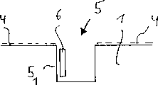
Fig. 9 a is the rear view of the first scheme embodiment, and groove 35 in this scheme
1, 35
2, 35
3On the reflection back wall 3 with the form embedded body 3 of retrography letter.Be respectively arranged with band light source 36 along these grooves
1, 36
2, 36
3, the partial cross section of its II-II line as can be seen from Fig. 9 b along Fig. 9 a.For realizing stereoeffect, also can be according to the configuration shown in Fig. 7 d along groove 35
iThree sides 1,2 ..., a plurality of light sources are set.As long as the narrow side of band light source can fully reflect, also can adopt the configuration shown in Fig. 7 c, wherein two band light source back-to-back are arranged on groove 35
iIn.But in order to realize also can adopting the configuration shown in Fig. 7 c with dark-coloured display ads stroke.When this situation, the setting of light source should make it only penetrate light in the wide side towards body 1.
Figure 10 a is the rear view of the alternative plan of second embodiment, and Figure 10 b is the partial section along III among Figure 10 a-III line.In this embodiment, groove 45
iExtend and respectively around the section 1 of body 1 projection along the profile of retrography character
iAt groove 45
iIn be provided with band light source 46
i, this light source and the identical in the first embodiment section 1 that light is incided body 1
iIn.This scheme of substituting, light source 46
iCan make light source only light be incided groove 45 by being provided with
iThe side in, this side and spatial dimension 1
iThe edge relative.The dark form in remaining illuminated light-emitting face 2 of stroke shows when this situation.In the embodiments of the present invention shown in Figure 10 a, the 10b, letter is not identical with first embodiment (Fig. 1), is formed by transparent body cutting fully, and only forms on body with relief shape.But light source is around the body spare that conforms to character when both of these case.So to spatial dimension 1
iIllumination can adopt and contrast first embodiment and Fig. 1-7 described identical measure optimizations.When needs made character protrude in light ground in dark-coloured mode, correspondingly will contrast the described principle of Fig. 1-7 was not to be used for spatial dimension 1
i, but be used to be positioned at spatial dimension 1
iBetween and should strengthen the part of the body of illumination.In another program, substitute dorsal part 3, but on light-emitting face 2, form groove 45 in reflection
I
For for simplicity, the band light source that illustrates all is arranged in the groove of opening in the above description.But also can cast to light source, wherein for example form groove at first as mentioned above, light source is arranged in the groove and then light source is cast in the groove.
Claims (14)
1. light-emitting device, have a body (1) that constitutes by transparent material, one or more light is incided light source and a light-emitting face (2) that is positioned at body one side in the body, incide light in the body by outgoing in the body by this light-emitting face, what wherein have a band shape at least vertically is that base company's supervention send the light source of light directly to be arranged on the body or in the body with it, light by a band light source towards body (6) side outgoing is entered in the body (1) substantially fully, it is characterized in that: the side (25a of body, 54a) part is formed on internal radiation reflection of light mirror or reverberator at least, this catoptron reflexes to light-emitting face (2) at least in part with light incident thereon, wherein forms a wall section (25a as crooked catoptron in a rib scope of body (1); 54a), this wall section will reflex to light-emitting face (2 by the light that band light source (6) directly project on it; 32).
2. according to the described light-emitting device of claim 1, it is characterized in that: be concave lens structure and abut against on the light-emitting face (32) as the catoptron of bending or the wall section (67) of reverberator formation.
3. according to the described light-emitting device of claim 1, it is characterized in that: the side (3 of the wall section (25a, 54a) that forms as the catoptron of bending or reverberator and the body that forms as catoptron or reverberator; 37) adjacency, this side are reflexed on the light-emitting face by a part of light that incides on it in the body (1) to the major general.
4. according to the described light-emitting device of claim 1, it is characterized in that one has first reflection configuration (25b) as the wall of the body of catoptron or reverberator formation, this wall will be incided on the wall (3) that light on it reflexes to second body that forms as catoptron or reverberator at least in part by the inside of body, and the light that this wall will incide on it reflexes on the light-emitting face (2) at least in part.
5. according to the described light-emitting device of claim 4, it is characterized in that: first of reflection configuration is crooked as the wall (25b) of catoptron or reflector structure.
6. according to the described light-emitting device of claim 5, it is characterized in that: first is as the wall and light-emitting face (2) adjacency of mirror structure.
7. according to the described light-emitting device of claim 1, it is characterized in that: one substantially parallel, relative with light-emitting face (2) as the face (3) of the body (1) of catoptron or reflector structure.
8. according to the described light-emitting device of claim 7, it is characterized in that, two straight faces (14a, 14b) as catoptron or reflector structure, these two faces are used to be reflected in the light of internal radiation, these two mutual angles of face are 90 °, wherein (14a) in these two faces with to exit facet substantially parallel, as the face (3) of catoptron or reflector structure join and therewith face (3) be that benchmark tilts.
9. according to the described light-emitting device of claim 1, it is characterized in that: band light source (6) is extended on the direction parallel with light-emitting face substantially.
10. according to the described light-emitting device of claim 1, it is characterized in that: the configuration of band light source (6) should make by its emission and the light that incides light-emitting face (2) has an incident angle greater than the angle of total reflection (a).
11. according to the described light-emitting device of claim 10, it is characterized in that: should make by its light as the setting of the face of the body (1) of mirror structure to have an incident angle at light-emitting face to light-emitting face (2) reflection, this incident angle is greater than the angle of total reflection, and light-emitting face (2) has the section of a uneven surface.
12. according to each described light-emitting device in the claim 1 to 11, it is characterized in that: body (1) has a rotational symmetric substantially shape and light-emitting face (72) is basic vertical with axis of symmetry.
13. according to each described light-emitting device in the claim 1 to 10, it is characterized in that, the light-emitting face of a rotational symmetric taper (32), this exit facet becomes awl to body (1) internal direction.
14. according to each described light-emitting device in the claim 1 to 11, it is characterized in that: this light-emitting device constitutes with character or a series of character shape.
Applications Claiming Priority (4)
| Application Number | Priority Date | Filing Date | Title |
|---|---|---|---|
| DE19606179.2 | 1996-02-20 | ||
| DE19606179A DE19606179A1 (en) | 1996-02-20 | 1996-02-20 | Outdoor display lettering illumination |
| DE29603225U DE29603225U1 (en) | 1996-02-20 | 1996-02-22 | Illuminating device for displaying characters |
| DE29603225.5 | 1996-02-22 |
Publications (1)
| Publication Number | Publication Date |
|---|---|
| CN2324748Y true CN2324748Y (en) | 1999-06-16 |
Family
ID=26023048
Family Applications (1)
| Application Number | Title | Priority Date | Filing Date |
|---|---|---|---|
| CN97290002U Expired - Lifetime CN2324748Y (en) | 1996-02-20 | 1997-02-20 | Light-projector |
Country Status (10)
| Country | Link |
|---|---|
| US (1) | US6079839A (en) |
| EP (1) | EP0821820B1 (en) |
| CN (1) | CN2324748Y (en) |
| AT (1) | ATE192873T1 (en) |
| CA (1) | CA2216945C (en) |
| DK (1) | DK0821820T3 (en) |
| ES (1) | ES2148969T3 (en) |
| GR (1) | GR3034164T3 (en) |
| PT (1) | PT821820E (en) |
| WO (1) | WO1997030431A2 (en) |
Cited By (1)
| Publication number | Priority date | Publication date | Assignee | Title |
|---|---|---|---|---|
| CN107680505A (en) * | 2017-10-26 | 2018-02-09 | 厦门大学嘉庚学院 | Laser light source display device |
Families Citing this family (14)
| Publication number | Priority date | Publication date | Assignee | Title |
|---|---|---|---|---|
| US6473554B1 (en) | 1996-12-12 | 2002-10-29 | Teledyne Lighting And Display Products, Inc. | Lighting apparatus having low profile |
| AT405633B (en) * | 1997-10-13 | 1999-10-25 | Magna Auteca Zweigniederlassun | Light |
| US6134092A (en) * | 1998-04-08 | 2000-10-17 | Teledyne Lighting And Display Products, Inc. | Illumination device for non-emissive displays |
| US6502968B1 (en) * | 1998-12-22 | 2003-01-07 | Mannesmann Vdo Ag | Printed circuit board having a light source |
| GB2362019A (en) * | 2000-03-14 | 2001-11-07 | Porter Lancastrian Ltd | An illuminated display panel. |
| DE10322561B4 (en) * | 2003-05-20 | 2011-06-22 | Isolar Isolierglaserzeugung Ges.M.B.H. | Insulating glass element with light frame |
| US7748873B2 (en) | 2004-10-07 | 2010-07-06 | Seoul Semiconductor Co., Ltd. | Side illumination lens and luminescent device using the same |
| ATE434814T1 (en) * | 2006-03-08 | 2009-07-15 | Fiat Ricerche | MODULAR ILLUMINATED DISPLAY |
| US20080127447A1 (en) * | 2006-11-30 | 2008-06-05 | Overaag Chad D | Floor care apparatus equipped with electroluminescent light source |
| KR101283129B1 (en) * | 2007-04-03 | 2013-07-05 | 엘지이노텍 주식회사 | Light guide plate, surface light source apparatus and display apparatus having thereof |
| KR100882801B1 (en) * | 2007-04-25 | 2009-02-09 | 박휴완 | Light guide plate lighting apparatus |
| CN202708988U (en) * | 2012-07-03 | 2013-01-30 | 深圳安嵘光电产品有限公司 | Light guide plate (LGP) and lighting lamp |
| DE202015105478U1 (en) * | 2015-10-16 | 2015-10-22 | Lauschner Lichtwerbung Gmbh | Illuminated symbol for advertising systems and advertising system with the light symbol |
| CN108885302B (en) * | 2016-03-29 | 2020-02-18 | 夏普株式会社 | Illumination device and display device |
Family Cites Families (6)
| Publication number | Priority date | Publication date | Assignee | Title |
|---|---|---|---|---|
| DE2542590A1 (en) * | 1975-09-24 | 1977-04-07 | Siemens Ag | DISPLAY DEVICE |
| FR2576441A1 (en) * | 1985-01-22 | 1986-07-25 | Blanchet Pierre | Light display device |
| JP2980776B2 (en) * | 1992-06-04 | 1999-11-22 | 東ソー株式会社 | Backlight |
| JPH07181484A (en) * | 1993-11-05 | 1995-07-21 | Internatl Business Mach Corp <Ibm> | Back light for liquid crystal display and liquid crystal display |
| FR2720181B1 (en) * | 1994-05-18 | 1996-08-02 | Sorelec | Display and signaling panel. |
| JP2853969B2 (en) * | 1994-12-26 | 1999-02-03 | スタンレー電気株式会社 | Surface light source device |
-
1997
- 1997-02-20 PT PT97919249T patent/PT821820E/en unknown
- 1997-02-20 CN CN97290002U patent/CN2324748Y/en not_active Expired - Lifetime
- 1997-02-20 ES ES97919249T patent/ES2148969T3/en not_active Expired - Lifetime
- 1997-02-20 DK DK97919249T patent/DK0821820T3/en active
- 1997-02-20 WO PCT/DE1997/000310 patent/WO1997030431A2/en active IP Right Grant
- 1997-02-20 EP EP97919249A patent/EP0821820B1/en not_active Expired - Lifetime
- 1997-02-20 CA CA002216945A patent/CA2216945C/en not_active Expired - Fee Related
- 1997-02-20 AT AT97919249T patent/ATE192873T1/en active
- 1997-02-20 US US08/945,064 patent/US6079839A/en not_active Expired - Lifetime
-
2000
- 2000-08-09 GR GR20000401859T patent/GR3034164T3/en unknown
Cited By (1)
| Publication number | Priority date | Publication date | Assignee | Title |
|---|---|---|---|---|
| CN107680505A (en) * | 2017-10-26 | 2018-02-09 | 厦门大学嘉庚学院 | Laser light source display device |
Also Published As
| Publication number | Publication date |
|---|---|
| DK0821820T3 (en) | 2000-10-02 |
| PT821820E (en) | 2000-11-30 |
| WO1997030431A3 (en) | 1997-10-09 |
| EP0821820A2 (en) | 1998-02-04 |
| US6079839A (en) | 2000-06-27 |
| CA2216945C (en) | 2001-09-11 |
| EP0821820B1 (en) | 2000-05-10 |
| GR3034164T3 (en) | 2000-11-30 |
| CA2216945A1 (en) | 1997-08-21 |
| ES2148969T3 (en) | 2000-10-16 |
| WO1997030431A2 (en) | 1997-08-21 |
| ATE192873T1 (en) | 2000-05-15 |
Similar Documents
| Publication | Publication Date | Title |
|---|---|---|
| CN2324748Y (en) | Light-projector | |
| US4996632A (en) | Multi-color illuminating system | |
| US7008097B1 (en) | Illumination device for simulating neon or fluorescent lighting including a waveguide and a scattering cap | |
| EP3212994B1 (en) | A lamp assembly for a vehicle | |
| JP2010251013A (en) | Lighting fixture | |
| JPH07279131A (en) | High luminance pattern light emitting display device | |
| JP2005327649A (en) | Vehicular lighting fixture unit and vehicular lighting fixture | |
| CN101029712B (en) | Lighting device | |
| US20080271856A1 (en) | Daylight Shielding Device | |
| JP2004121810A (en) | Light emitting ornament body for win hole of pachinko game machine | |
| JP2008147032A (en) | Vehicular lamp | |
| US6224246B1 (en) | Signal lamp for vehicles | |
| US20110310625A1 (en) | Light Fixtures Comprising Organic Light Emitting Diodes | |
| EP0355815A3 (en) | Headlamp unit for motor vehicles | |
| US20120039076A1 (en) | Energy-saving lighting device with even distribution of light | |
| CN210601465U (en) | Vehicle lamp | |
| KR20190052690A (en) | Illuminator with asymmetric light distribution pattern | |
| CN213299686U (en) | Side-lighting side-bending neon lamp strip | |
| CN1460163A (en) | Luminaire | |
| KR20190045431A (en) | Lighting apparatus of LED | |
| CN219201973U (en) | Optical grade light guide plate with double-sided treatment | |
| CN219063218U (en) | LED outdoor lamp | |
| US11333805B1 (en) | Low glare luminaires | |
| CN211203681U (en) | Side-lighting hollow flat lamp | |
| CN209960238U (en) | Lamp fitting |
Legal Events
| Date | Code | Title | Description |
|---|---|---|---|
| C14 | Grant of patent or utility model | ||
| GR01 | Patent grant | ||
| C17 | Cessation of patent right | ||
| CX01 | Expiry of patent term |