CN219342832U - Full prefabricated expansion joint component of concrete segment pin-connected panel - Google Patents
Full prefabricated expansion joint component of concrete segment pin-connected panel Download PDFInfo
- Publication number
- CN219342832U CN219342832U CN202320302266.6U CN202320302266U CN219342832U CN 219342832 U CN219342832 U CN 219342832U CN 202320302266 U CN202320302266 U CN 202320302266U CN 219342832 U CN219342832 U CN 219342832U
- Authority
- CN
- China
- Prior art keywords
- prefabricated
- expansion joint
- concrete segment
- component
- joint component
- Prior art date
- Legal status (The legal status is an assumption and is not a legal conclusion. Google has not performed a legal analysis and makes no representation as to the accuracy of the status listed.)
- Active
Links
Images


Abstract
The utility model discloses a concrete segment assembled full-prefabricated expansion joint component, which is arranged between two oppositely arranged beam plates, wherein a positioning piece and a reinforcing steel bar are buried in the prefabricated components, and two adjacent prefabricated components are mutually spliced through the positioning piece and are respectively arranged on the beam plates at two sides, so that an elastic connecting piece is arranged between the prefabricated components at two sides to form the expansion joint component which is flush with bridge deck pavement, and the expansion joint component can meet bridge deck deformation requirements.
Description
Technical Field
The utility model relates to the technical field of bridge construction, in particular to a concrete segment assembled full-prefabricated expansion joint component.
Background
The bridge expansion joint is a device arranged between bridge ends, between the bridge ends and bridge abutment or at the hinge position of the bridge in order to meet the requirement of bridge deck deformation. The expansion joint is required to be freely telescopic in two directions parallel to and perpendicular to the axis of the bridge, so that the expansion joint is firm and reliable, and the vehicle is smooth and free from sudden jump and noise when running; can prevent rainwater and garbage soil from penetrating and blocking; the installation, inspection, maintenance and dirt elimination are all simple and convenient. At the expansion joint, the railing and the bridge deck pavement are disconnected.
The bridge expansion joint is mainly composed of an elastomer expansion joint, a shear expansion joint, a steel support expansion joint, a modulus support expansion joint and a butt joint expansion joint. But bridge expansion joint can lead to the telescoping device to damage because of the influence of factors such as its installation and bridge floor are uneven, bridge deck pavement ageing, in addition because receive the repetitive action of wheel load, often can appear expansion joint disease, shaped steel expansion joint produces "jump car", shaped steel fracture easily, when the phenomenon takes place of jumping, can lead to anchor district concrete to receive the impact effect of car load repeatedly and fracture even damage, finally because the expansion joint damage is serious and need carry out the whole change.
At present, the expansion joint replacement is generally carried out in a sealing way and on-site construction way (the form of the expansion joint is not changed), the anchoring area concrete is generally cast in situ and repaired by adopting steel fiber concrete, but the performance of the common steel fiber concrete is difficult to keep normal work under long-term automobile load without cracks and damages. Some students adopt steel fiber ultra-high performance concrete to pour an anchoring area, the ultra-high performance concrete can work normally under long-term automobile load due to high strength and high durability, but the steel fiber has high manufacturing cost, the workability is reduced during the construction of the ultra-high performance concrete to cause difficult forming, the performance of the ultra-high performance concrete cannot be exerted, more time is required for on-site pouring, the influence on roads with larger traffic, particularly highways, is larger, some students adopt a mode of prefabricating general components to reduce the construction difficulty and the construction time, and a part of components are required for on-site pouring construction.
The prior art has complex steps for replacing the expansion joint, increases the construction time of constructors, has low efficiency and high material cost, and is difficult to meet the replacement of the expansion joint of a modern bridge.
Disclosure of Invention
In order to overcome the defects in the prior art, the utility model aims to provide the concrete segment assembled full-prefabricated expansion joint component, which has a smart structure, can meet the bridge deck deformation requirement, is convenient to replace, reduces the labor intensity of constructors, improves the construction efficiency, and is beneficial to the application and popularization of the full-prefabricated expansion joint component in the technical field of bridge construction.
In order to achieve the aim, the utility model adopts the following technical scheme that a concrete segment spliced full-prefabricated expansion joint component is arranged between two oppositely arranged beam plates; the connecting device comprises prefabricated parts and elastic connecting pieces, wherein two adjacent prefabricated parts are spliced with each other and are respectively arranged on two beam plates, concave-convex clamping grooves which are mutually matched and connected are formed in the connecting positions of the prefabricated parts and the elastic connecting pieces, and the elastic connecting pieces are connected between the two prefabricated parts which are oppositely arranged.
As a preferable scheme of the utility model, one end of the prefabricated part is provided with a positioning piece, the other end of the prefabricated part is provided with a positioning hole, and the positioning piece is embedded into the positioning hole to realize the assembly of two adjacent prefabricated parts.
As a preferable scheme of the utility model, the prefabricated part is also provided with a grouting pipeline, and the grouting pipeline is communicated with the positioning hole.
As a preferable scheme of the utility model, the number of the positioning pieces is two, and the two positioning pieces are arranged in parallel.
As a preferable scheme of the utility model, the prefabricated part is embedded with the steel bars in the anchoring area and the U-shaped steel bars.
As a preferable scheme of the utility model, the steel bars in the anchoring area are buried in the prefabricated part with the openings facing downwards, and the steel bars of which the two ends extend out of the prefabricated part are used for connecting the beam plates.
As a preferable scheme of the utility model, the beam plate is provided with a bar planting hole matched with the steel bar in the anchoring area.
As a preferable scheme of the utility model, a plurality of reinforcing steel bars formed by connecting the U-shaped reinforcing steel bars with the reinforcing steel bars of the anchoring area are distributed on the prefabricated part at equal intervals.
As a preferred embodiment of the present utility model, the prefabricated parts are connected with the elastic connecting pieces in a staggered manner and are flush with the surface of the bridge deck pavement layer.
As a preferable mode of the utility model, the connection part of the prefabricated part and the elastic connecting piece is in a ladder-shaped structure.
Compared with the prior art, the method has the following beneficial effects: according to the concrete segment assembled type full-prefabricated expansion joint component, the prefabricated components are arranged between two oppositely arranged beam plates, the two adjacent prefabricated components are spliced with each other and are respectively arranged between the two beam plates, the elastic connecting piece is arranged between the prefabricated components oppositely arranged at two sides, so that the bridge deck deformation requirement can be met, the prefabricated components are convenient to install and detach, the replacement time of the expansion joint component is shortened, the structure of the component is simple and ingenious, the labor intensity of constructors is reduced, the construction efficiency is improved, and the full-prefabricated expansion joint component is beneficial to application and popularization in the technical field of bridge construction.
Further, the prefabricated part of the expansion joint component is buried with the steel bars in the anchoring area and the U-shaped steel bars, and the steel bars in the anchoring area are connected with the beam plate, so that the prefabricated part can be more firmly installed on the beam plate, and the steel bars in the anchoring area and the U-shaped steel bars are fixedly connected to form a steel bar net which is uniformly distributed in the prefabricated part, so that the structural stability of the whole prefabricated part is improved.
Further, the prefabricated part and the elastic connecting piece of the expansion joint component are provided with the concave-convex clamping groove structure, so that the elastic connecting piece and the prefabricated part can be mutually matched and installed, the structure is ingenious, the installation and the disassembly of the expansion joint component are facilitated, and the construction efficiency is improved.
Drawings
FIG. 1 is a sectional view of a concrete segment fabricated fully prefabricated expansion joint member according to embodiment 1;
FIG. 2 is a schematic structural view of a precast concrete segment-assembled fully precast expansion joint member in embodiment 1;
FIG. 3 is a schematic structural view of an elastic connector for a concrete segment fabricated fully prefabricated expansion joint member in embodiment 1;
FIG. 4 is a schematic structural view of a concrete segment assembled fully prefabricated expansion joint member grouting pipe in embodiment 1;
FIG. 5 is a top view of a concrete segment fabricated fully prefabricated expansion joint component of example 1;
FIG. 6 is a schematic view of an installation of a concrete segment fabricated fully prefabricated expansion joint component in example 2;
fig. 7 is a top view of a concrete segment fabricated fully prefabricated expansion joint component in embodiment 2.
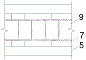
Reference numerals: 1. a beam plate; 2. anchoring area steel bars; 3. a positioning piece; 4. u-shaped reinforcing steel bars; 5. a bridge deck pavement layer; 6. grouting pipelines; 7. a prefabricated member; 8. positioning holes; 9. an elastic connection member.
Detailed Description
Embodiments of the present utility model will be described in detail below with reference to the accompanying drawings.
Example 1: as shown in fig. 1 to 5, a concrete segment assembly type full-prefabricated expansion joint component is arranged between two oppositely arranged beam plates 1 and comprises a prefabricated component 7 and an elastic connecting piece 9, wherein the elastic connecting piece 9 is made of vulcanized rubber, has higher elasticity and tensile strength, can adapt to the deformation of a bridge deck, the prefabricated component 7 is made of concrete blocks, has the length of 0.5m, and is provided with an uneven clamping groove structure at the joint of the elastic connecting piece 9 and the prefabricated component 7, so that the elastic connecting piece 9 and the prefabricated component 7 can be connected with each other through the uneven clamping groove structure. In order to increase the connection firmness between the prefabricated parts 7, a plurality of prefabricated parts 7 are respectively installed on the two side beam plates 1 by mutually splicing, so that the elastic connecting piece 9 can be installed between the prefabricated parts 7 which are oppositely arranged at two sides.
The bridge expansion joint installation of the prior art firstly comprises slotting on a paved bridge deck, placing an expansion joint device in the slot, welding an anchoring reinforcing steel bar of the expansion joint device and a reserved reinforcing steel bar in the slot, then filling a template and pouring concrete, and the whole installation process has more steps and high labor intensity. The expansion joint component is installed by mutually splicing the prefabricated components 7 on the beam plates 1 on the two sides through injecting epoxy mortar, and then the elastic connecting piece 9 is connected between the prefabricated components 7 on the two sides, so that the expansion joint component is flush with the surface of the bridge deck pavement layer 5, the process is completed before bridge deck pavement, and the steps of welding reinforcing steel bars, filling templates and the like are omitted. Meanwhile, the prefabricated part 7 is made of concrete, so that the cost is lower than that of an expansion joint device in the prior art, and the material cost is saved.
The locating piece 3 of this embodiment is longitudinal reinforcement, and two adjacent prefabricated components 7 need install on beam slab 1 through the concatenation, consequently will two above-mentioned locating pieces 3 parallel and vertically bury in above-mentioned prefabricated components 7 the inside, simultaneously, set up the distance that locating piece 3 front end stretches out prefabricated components 7 preceding terminal surface 5cm, locating piece 3 rear end leaves 5cm apart from prefabricated components 7 rear end face apart from the distance, forms the locating hole 8 that is used for other locating pieces 3 male. The front end of the positioning member 3 of another prefabricated element 7 can be inserted into the positioning hole 8 of the previous prefabricated element 7, so that the prefabricated elements 7 are connected through longitudinal steel bars.
In order to make the connection between the prefabricated parts 7 stronger, the vertical side of the grouting pipe 6 penetrates through the prefabricated parts 7 and is communicated with the positioning holes 8, the grouting pipe 6 penetrates through the prefabricated parts 7 to the beam plate 1, and the injected epoxy mortar flows onto the beam plate 1, so that the prefabricated parts 7 and the beam plate 1 can be bonded together better. The horizontal side of the grouting pipeline 6 is communicated with the positioning holes 8 on the two sides, so that the whole grouting pipeline 6 and the positioning holes 8 on the two sides are communicated, and then epoxy mortar can be injected into the positioning holes 8 on the two sides through the upper port of the grouting pipeline 6, so that the connection between the longitudinal steel bars in the positioning holes 8 and the prefabricated parts 7 is firmer, and the overall structural stability formed by connecting the prefabricated parts 7 is improved.
The prefabricated component 7 of this embodiment is buried in anchor district reinforcing bar 2 and U shaped steel muscle 4, and anchor district reinforcing bar 2 passes through welded fastening connection with U shaped steel muscle 4. In order to enable the prefabricated member 7 to be fixedly installed on the beam slab 1, the anchoring area steel bars 2 are arranged to be U-shaped, and the openings of the anchoring area steel bars are buried in the prefabricated member 7 downwards, so that part of the steel bars at two ends of the anchoring area steel bars 2 extend out of the prefabricated member 7 and are used for connecting the beam slab 1.
Because the steel bars 2 in the anchoring area need to be inserted into the beam slab 1, the beam slab 1 is provided with the steel bar planting holes which are matched with the steel bars 2 in the anchoring area, and the prefabricated part 7 and the beam slab 1 can be fixedly connected together through the steel bars 2 in the anchoring area.
In order to increase the structural firmness of the prefabricated part 7, the prefabricated part 7 is made of basalt fiber ultra-high performance concrete, the material is high in strength and low in manufacturing cost, the construction cost is saved, the service life is prolonged, structural adhesive is coated on the contact surface of the prefabricated part 7 and the bridge deck pavement layer 5, and the bonding performance of the prefabricated part 7 and the bridge deck pavement layer 5 is guaranteed. In order to ensure the connection stability of the steel bars 2 in the anchoring area and the prefabricated parts 7, the steel bars 2 in the anchoring area and the U-shaped steel bars 4 are fixedly connected to form a steel bar net, the structure of the steel bar net is firmer, the steel bars 2 in the anchoring area and the prefabricated parts 7 are connected more tightly, the steel bar net is distributed in the prefabricated parts 7 at equal intervals, and the structural strength of the prefabricated parts 7 is improved.
Because the expansion joint component needs to have enough strength and rigidity, the prefabricated component 7 and the elastic connecting piece 9 are arranged for staggered joint connection, so that the stress of the expansion joint is more uniform, and the integral structural firmness is increased. In addition, the prefabricated part 7 is step-shaped structure and elastic connection piece 9 looks adaptation, and the expansion joint component that both connect the formation and bridge deck pavement layer 5 surface parallel and level can prevent effectively that the fracture of prefabricated part 7 that leads to because the jump car from, has improved the security that the vehicle was used and the life of expansion joint component.
In order to make the prefabricated component 7 more firm with the connection of elastic connection piece 9, increase expansion joint component overall structure intensity, do rough treatment at prefabricated component 7 and elastic connection piece 9 surface, increased with beam slab 1 and bridge deck pavement layer 5's connectivity, and this structure installation dismantles conveniently, has also effectively promoted the efficiency of construction. In addition, in order to further increase the structural strength, structural adhesive is smeared on the connecting surface of the clamping groove of the prefabricated part 7 and the elastic connecting piece 9, so that the integral firmness of the prefabricated part 7 and the elastic connecting piece 9 is increased.
The full prefabricated expansion joint component of concrete segment pin-connected panel in this embodiment sets up between two beam slabs 1 of relative setting, and two adjacent prefabricated components 7 are through mutually concatenation and install respectively in both sides beam slab 1, make elastic connection spare 9 install between the prefabricated components 7 of the relative setting in both sides, form expansion joint component, can satisfy bridge floor deformation requirement, and it is convenient to change moreover, this expansion joint component structure is ingenious, reduced constructor's intensity of labour, improved the efficiency of construction, be favorable to the application and the popularization of the full prefabricated expansion joint component of above-mentioned concrete segment pin-connected panel in bridge construction technical field.
Example 2: as shown in fig. 6 to 7, this embodiment is distinguished from embodiment 1 in that: the expansion joint component in this embodiment sets up elastic connection spare 9 to be the structure of zigzag all around, and prefabricated component 7 also sets up corresponding zigzag structure with the junction surface of elastic connection spare 9, makes elastic connection spare 9 and prefabricated component 7 can be connected through mortise and tenon fourth of the twelve earthly branches structure, forms expansion joint component, and this connected mode is simple to operate not only, has also increased expansion joint component's overall structure intensity.
The previous description of the disclosed embodiments is provided to enable any person skilled in the art to make or use the present utility model. Various modifications to these embodiments will be readily apparent to those skilled in the art, and the generic principles defined herein may be applied to other embodiments without departing from the spirit or scope of the utility model; thus, the present utility model is not intended to be limited to the embodiments shown herein but is to be accorded the widest scope consistent with the principles and novel features disclosed herein.
Although the reference numerals in the figures are used more herein: 1. a beam plate; 2. anchoring area steel bars; 3. a positioning piece; 4. u-shaped reinforcing steel bars; 5. a bridge deck pavement layer; 6. grouting pipelines; 7. a prefabricated member; 8. positioning holes; 9. elastic connectors, etc., but do not exclude the possibility of using other terms. These terms are used merely for convenience in describing and explaining the nature of the utility model; they are to be interpreted as any additional limitation that is not inconsistent with the spirit of the present utility model.
Claims (10)
1. A concrete segment assembled full prefabricated expansion joint component is characterized in that: the beam plates are arranged between two oppositely arranged beam plates (1); including prefabricated component (7) and elastic connection spare (9), adjacent two splice each other between prefabricated component (7) and install respectively in two beam slab (1), prefabricated component (7) with elastic connection spare (9) junction is equipped with the unsmooth form draw-in groove of mutually supporting connection, elastic connection spare (9) are connected in two relative settings between prefabricated component (7).
2. The concrete segment fabricated fully prefabricated expansion joint member according to claim 1, wherein: one end of the prefabricated part (7) is provided with a positioning piece (3), the other end of the prefabricated part is provided with a positioning hole (8), and two adjacent prefabricated parts (7) are assembled by embedding the positioning piece (3) into the positioning hole (8).
3. The concrete segment fabricated fully prefabricated expansion joint member according to claim 2, wherein: the prefabricated part (7) is further provided with a grouting pipeline (6), and the grouting pipeline (6) is communicated with the positioning hole (8).
4. The concrete segment fabricated fully prefabricated expansion joint member according to claim 2, wherein: the number of the positioning pieces (3) is two, and the two positioning pieces (3) are arranged in parallel.
5. The concrete segment fabricated fully prefabricated expansion joint member according to claim 1, wherein: the prefabricated part (7) is buried with an anchor area steel bar (2) and a U-shaped steel bar (4).
6. The concrete segment fabricated fully prefabricated expansion joint component according to claim 5, wherein: the opening of the steel bar (2) in the anchoring area is downwards embedded in the prefabricated part (7), and part of the steel bars extending out of the prefabricated part (7) at two ends of the steel bar (2) in the anchoring area are used for connecting the beam slab (1).
7. The concrete segment fabricated fully prefabricated expansion joint component according to claim 6, wherein: the beam plate (1) is provided with a bar planting hole matched with the steel bar (2) in the anchoring area.
8. The concrete segment fabricated fully prefabricated expansion joint component according to claim 5, wherein: the U-shaped steel bars (4) and the steel bar meshes formed by connecting the steel bars (2) in the anchoring area are distributed on the prefabricated part (7) at equal intervals.
9. The concrete segment fabricated fully prefabricated expansion joint member according to claim 2, wherein: the prefabricated part (7) is connected with the elastic connecting piece (9) in a staggered way and is flush with the surface of the bridge deck pavement layer (5).
10. The concrete segment fabricated fully prefabricated expansion joint member according to claim 9, wherein: the connection part of the prefabricated part (7) and the elastic connecting piece (9) is in a ladder-shaped structure.
Priority Applications (1)
| Application Number | Priority Date | Filing Date | Title |
|---|---|---|---|
| CN202320302266.6U CN219342832U (en) | 2023-02-24 | 2023-02-24 | Full prefabricated expansion joint component of concrete segment pin-connected panel |
Applications Claiming Priority (1)
| Application Number | Priority Date | Filing Date | Title |
|---|---|---|---|
| CN202320302266.6U CN219342832U (en) | 2023-02-24 | 2023-02-24 | Full prefabricated expansion joint component of concrete segment pin-connected panel |
Publications (1)
| Publication Number | Publication Date |
|---|---|
| CN219342832U true CN219342832U (en) | 2023-07-14 |
Family
ID=87108258
Family Applications (1)
| Application Number | Title | Priority Date | Filing Date |
|---|---|---|---|
| CN202320302266.6U Active CN219342832U (en) | 2023-02-24 | 2023-02-24 | Full prefabricated expansion joint component of concrete segment pin-connected panel |
Country Status (1)
| Country | Link |
|---|---|
| CN (1) | CN219342832U (en) |
-
2023
- 2023-02-24 CN CN202320302266.6U patent/CN219342832U/en active Active
Similar Documents
| Publication | Publication Date | Title |
|---|---|---|
| KR102009134B1 (en) | Construction Method of Long Span Girder Bridge | |
| CN107815963A (en) | A kind of bridge expanssion joint | |
| CN103249893A (en) | Floor slab structure for bridge | |
| KR101732669B1 (en) | Reinforcement member, concrete box reinforced with the same and the construction method thereof | |
| KR20200098250A (en) | Hybrid segment for shield tbm tunnel | |
| CN219342832U (en) | Full prefabricated expansion joint component of concrete segment pin-connected panel | |
| KR20090008070A (en) | A superstructure of a prefabricated bridge | |
| KR100563787B1 (en) | Retaining wall structure composed of retaining-wall panel unit prestressed under interconnecting high intensity reinforcing rod installed in the panel unit with couplers so as to resist section strength and constructing method thereof | |
| KR101194482B1 (en) | The steel systhesis beam and the method threreof | |
| KR100690395B1 (en) | Continuous Beam Construction Method of Prestressed Concrete Beam | |
| KR102386348B1 (en) | Girder installed strengthen and space cap device | |
| KR101298581B1 (en) | Connecting structures and methods between frp decks, and deck and girder for tubular deck unit with hybrid connection of snap-fit and bonding | |
| CN210262550U (en) | Asphalt pavement structure based on cement pavement | |
| CN204590336U (en) | A kind of overlapped shear wall based on half prefabricated ultra-tough steel concrete | |
| CN113957787A (en) | Semi-assembly type concrete guardrail and mounting method thereof | |
| CN113605930A (en) | Assembly type tunnel bottom structure replacing inverted arch filling layer and construction method | |
| KR20120134677A (en) | The precast concrete closed conduit that is reinforced by the shear connector and constructing method of it | |
| CN105220809A (en) | The syndeton of a kind of arch top board and bracket stake and construction method thereof | |
| CN205653709U (en) | Reinforced (rfd) a chain of cuff device of hollow slab bridge | |
| CN212983609U (en) | Temporary pre-stressed anchoring device for assembling precast concrete segment box girder | |
| KR100775936B1 (en) | Lining board and method manufacturing of the same | |
| CN220099552U (en) | New and old roadbed and pavement splicing structure capable of avoiding occurrence of cracks | |
| CN216947837U (en) | Highway bridge multislice telescoping device | |
| KR20050105768A (en) | Coupler tension type fabricated retaining wall built by connecting high intensity reinforcing bars installed in the retaining wall panel unit by coupler and prestressing those bars, and constructing method thereof | |
| KR20100120628A (en) | The assembly joint material |
Legal Events
| Date | Code | Title | Description |
|---|---|---|---|
| GR01 | Patent grant | ||
| GR01 | Patent grant |