CN219341600U - Automatic lifting type lifter - Google Patents
Automatic lifting type lifter Download PDFInfo
- Publication number
- CN219341600U CN219341600U CN202320349242.6U CN202320349242U CN219341600U CN 219341600 U CN219341600 U CN 219341600U CN 202320349242 U CN202320349242 U CN 202320349242U CN 219341600 U CN219341600 U CN 219341600U
- Authority
- CN
- China
- Prior art keywords
- sets
- lead screw
- automatic lifting
- frame
- lifting
- Prior art date
- Legal status (The legal status is an assumption and is not a legal conclusion. Google has not performed a legal analysis and makes no representation as to the accuracy of the status listed.)
- Active
Links
Images


Classifications
-
- Y—GENERAL TAGGING OF NEW TECHNOLOGICAL DEVELOPMENTS; GENERAL TAGGING OF CROSS-SECTIONAL TECHNOLOGIES SPANNING OVER SEVERAL SECTIONS OF THE IPC; TECHNICAL SUBJECTS COVERED BY FORMER USPC CROSS-REFERENCE ART COLLECTIONS [XRACs] AND DIGESTS
- Y02—TECHNOLOGIES OR APPLICATIONS FOR MITIGATION OR ADAPTATION AGAINST CLIMATE CHANGE
- Y02B—CLIMATE CHANGE MITIGATION TECHNOLOGIES RELATED TO BUILDINGS, e.g. HOUSING, HOUSE APPLIANCES OR RELATED END-USER APPLICATIONS
- Y02B50/00—Energy efficient technologies in elevators, escalators and moving walkways, e.g. energy saving or recuperation technologies
Landscapes
- Warehouses Or Storage Devices (AREA)
Abstract
The utility model relates to the technical field of lifting equipment, in particular to an automatic lifting type lifter which can fully utilize working hours of workers, avoid waste of working hours and effectively improve use convenience; including board, elevator motor, initiative lead screw, driven lead screw, the belt, the crane, two sets of cylinders, lift tray and buffer memory frame, the board bottom is equipped with four sets of landing legs, the fixed mount that is equipped with in board top, elevator motor fixed mounting is on the mount, the rotation of initiative lead screw and driven lead screw symmetry is installed on the mount, and the top and the output fixed connection of elevator motor of initiative lead screw, the left end and the output fixed connection of cylinder of lift tray, the board top is equipped with the draw-in groove, be equipped with two sets of pivots on the buffer memory frame, the buffer memory frame is rotated through the cooperation of pivot and pinhole and is installed on the constant head tank, all overlap in two sets of pivots and be equipped with the torsional spring, the one end and the board of two sets of torsional springs are connected, the other end and the buffer memory frame of two sets of torsional springs are connected.
Description
Technical Field
The utility model relates to the technical field of lifting equipment, in particular to an automatic lifting type lifter.
Background
Logistics storage is to utilize a self-built or leased warehouse, a site, storage, safekeeping, loading and unloading, carrying and delivering goods, and in the workflow of logistics storage, goods are usually piled up so as to be stored, when the goods are piled up, an elevator is used to lift the goods from a low place to a high place, and then subsequent piling is carried out.
In the actual working process, goods are placed on the lifting equipment, the goods are lifted to the required height by the lifting equipment, and then the workers operate the stacking device to move the goods from the lifting equipment to be stacked.
However, in the existing lifting equipment, in the actual use process, after the workers wait for the lifting tray to descend, the workers are required to place the goods on the lifting tray, so that the working time efficiency of the workers is wasted, and the use convenience is relatively poor.
Disclosure of Invention
In order to solve the technical problems, the utility model provides the automatic lifting type lifter which can fully utilize working hours of workers, avoid waste of working hours and effectively improve the use convenience.
The utility model relates to an automatic lifting type lifter, which comprises a machine table, wherein four groups of supporting legs are arranged at the bottom end of the machine table, a fixing frame is fixedly arranged at the top end of the machine table, the automatic lifting type lifter further comprises a lifting motor, a driving screw rod, a driven screw rod, a belt, a lifting frame, two groups of air cylinders, a lifting tray and a buffer storage frame, wherein the lifting motor is fixedly arranged on the fixing frame, the driving screw rod and the driven screw rod are symmetrically and rotationally arranged on the fixing frame, the top end of the driving screw rod is fixedly connected with the output end of the lifting motor, belt pulleys are fixedly sleeved at the bottom ends of the driving screw rod and the driven screw rod, the belt is rotationally sleeved on the two groups of belt pulleys, two groups of screw sleeves are fixedly arranged on the lifting frame and are respectively and spirally sleeved on the driving screw rod and the driven screw rod, the two groups of air cylinders are symmetrically and fixedly arranged on the lifting frame, the lifting tray is slidably arranged on the lifting frame, the left end of the lifting tray is fixedly connected with the output end of the air cylinders, two groups of pin holes are arranged in the buffer storage frame, two groups of rotating shafts are rotationally arranged on the buffer storage frame through the matching of the rotating shafts and the pin holes on the positioning groove, one ends of the two groups of the rotating shafts are respectively connected with the other ends of the two groups of torsion springs.
The utility model relates to an automatic lifting type lifter, which further comprises a rotating roller, wherein a slot is formed in the left end of a buffer storage frame, and the rotating roller is rotatably arranged on the slot.
The right end of the lifting tray is connected with a front shovel.
The utility model relates to an automatic lifting type lifter, which further comprises a protective cover, wherein the protective cover is detachably arranged at the bottom end of a machine table.
According to the automatic lifting type lifter disclosed by the utility model, the anti-collision pad is connected to the inner wall on the right side of the buffer storage frame.
According to the automatic lifting type lifter disclosed by the utility model, the inner walls of the front side and the rear side of the lifting frame are respectively connected with the sliding pads.
According to the automatic lifting type lifter disclosed by the utility model, two groups of reinforcing plates are symmetrically connected to the fixing frame, and the bottom ends of the two groups of reinforcing plates are connected with the top end of a machine table.
The utility model relates to an automatic lifting type lifter, which further comprises four groups of universal wheels, wherein the four groups of universal wheels are respectively and fixedly arranged at the bottom ends of the four groups of supporting legs.
Compared with the prior art, the utility model has the beneficial effects that: firstly, when using, the staff places the goods on the buffer memory frame, under the effect of goods, buffer memory frame lies in the draw-in groove, this moment buffer memory frame inboard horizontal one end and board top level, then through starting elevator motor, elevator motor drives the initiative lead screw and rotates, the initiative lead screw passes through the cooperation of belt pulley and belt and drives driven lead screw and rotate, initiative lead screw and driven lead screw drive the crane decline through the screw-thread fit with the swivel nut, make lift tray bottom and board top contact, then through starting the cylinder, the cylinder promotes the lift tray and moves right, under the stop of buffer memory frame, with smooth shovel of goods on the lift tray, the counter-rotating of rethread elevator motor, with the lift tray promotion, the staff only need place the goods on the buffer memory frame, need not wait for the lift tray whereabouts can, conveniently transport other goods in this period, thereby can make full use of staff's man-hour, avoid causing man-hour waste, initially, the buffer memory frame is in the state of tilting to the right side, can make buffer memory frame reset, in order to guarantee that the buffer memory frame right side is lower, convenience goods are placed, effectively improve the convenience.
Drawings
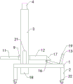
Fig. 1 is a schematic front side view of the present utility model.
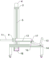
Fig. 2 is a schematic view of the front cross-sectional structure of the present utility model.
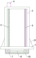
Fig. 3 is a left side partial structure schematic view of the present utility model.
Fig. 4 is a schematic view of a partial cross-sectional structure of the upper side of the crane installation according to the utility model.
FIG. 5 is a schematic view of a partial cross-sectional top view of the mounting of the cache shelf of the present utility model.
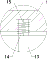
Fig. 6 is a partially enlarged schematic construction of the present utility model at a.
The reference numerals in the drawings: 1. a machine table; 2. a support leg; 3. a fixing frame; 4. a lifting motor; 5. a driving screw rod; 6. a driven screw rod; 7. a belt pulley; 8. a belt; 9. a lifting frame; 10. a screw sleeve; 11. a cylinder; 12. lifting the tray; 13. a cache rack; 14. a rotating shaft; 15. a torsion spring; 16. a rotating roller; 17. a front shovel; 18. a protective cover; 19. a crash pad; 20. a slide pad; 21. a reinforcing plate; 22. and a universal wheel.
Detailed Description
The following describes in further detail the embodiments of the present utility model with reference to the drawings and examples. The following examples are illustrative of the utility model and are not intended to limit the scope of the utility model.
As shown in fig. 1 to 6, the automatic lifting elevator comprises a machine table 1, wherein four groups of supporting legs 2 are arranged at the bottom end of the machine table 1, a fixing frame 3 is fixedly arranged at the top end of the machine table 1, the automatic lifting elevator also comprises a lifting motor 4, a driving screw rod 5, a driven screw rod 6, a belt 8, a lifting frame 9, two groups of air cylinders 11, a lifting tray 12 and a buffer frame 13, the lifting motor 4 is fixedly arranged on the fixing frame 3, the driving screw rod 5 and the driven screw rod 6 are symmetrically and rotatably arranged on the fixing frame 3, the top end of the driving screw rod 5 is fixedly connected with the output end of the lifting motor 4, belt pulleys 7 are fixedly sleeved at the bottom ends of the driving screw rod 5 and the driven screw rod 6, the belt 8 is rotatably sleeved on the two groups of belt pulleys 7, two groups of screw sleeves 10 are fixedly arranged on the lifting frame 9, the two groups of screw sleeves 10 are respectively and spirally sleeved on the driving screw rod 5 and the driven screw rod 6, the two groups of air cylinders 11 are symmetrically and fixedly arranged on the lifting frame 9, the lifting tray 12 is slidably arranged on the lifting frame 9, the left end of the lifting tray 12 is fixedly connected with the output end of the air cylinders 11, the machine table 1 is provided with clamping grooves, the top end of the machine table 1 is fixedly provided with the clamping grooves, the clamping grooves are fixedly sleeved at the top ends, the clamping grooves are respectively, the two groups of rotating shafts 15 are respectively arranged on the buffer frames 15 and are in the buffer frames 15 and are matched with the two groups of rotating shafts 15, 15 are matched with the two end shafts 15, 15 are fixedly connected with the other ends 15; firstly, when in use, a worker places goods on the buffer storage rack 13, under the action of the goods, the buffer storage rack 13 lies in the clamping groove, at this moment, one end of the inner side of the buffer storage rack 13 is horizontal with the top end of the machine table 1, then the lifting motor 4 is started to drive the driving screw rod 5 to rotate, the driving screw rod 5 drives the driven screw rod 6 to rotate through the cooperation of the belt pulley 7 and the belt 8, the driving screw rod 5 and the driven screw rod 6 drive the lifting rack 9 to descend through the threaded cooperation with the threaded sleeve 10, the bottom end of the lifting tray 12 is contacted with the top end of the machine table 1, then the lifting tray 12 is pushed to move rightwards through the starting cylinder 11, the goods are smoothly shoveled on the lifting tray 12 under the blocking of the buffer storage rack 13, and then the lifting tray 12 is lifted up through the reverse rotation of the lifting motor 4, the worker only needs to place the goods on the buffer storage rack 13 without waiting for the falling of the lifting tray 12, thus the working hours of the worker can be fully utilized, the waste of the working hours is avoided, the buffer storage rack 13 is in a rightwards inclined state in the initial stage, the buffer storage rack 13 can be reset, the right side of the buffer storage rack 13 can be reset, the convenience is ensured, and the convenience is improved.
The utility model relates to an automatic lifting type lifter, which further comprises a rotating roller 16, wherein a slot is formed in the left end of a buffer storage rack 13, and the rotating roller 16 is rotatably arranged on the slot; by arranging the roller 16, the roller 16 rolls in the rightward moving process of the lifting tray 12, and the rolling friction is used for replacing the sliding friction, so that the direct friction between the lifting tray 12 and the buffer frame 13 is reduced, and the use limitation is reduced.
The right end of the lifting tray 12 is connected with a front shovel 17; by providing the front shovel 17, the lifting tray 12 can be more easily shoveled up with the goods, and the use reliability is improved.
The utility model relates to an automatic lifting type lifter, which also comprises a protective cover 18, wherein the protective cover 18 is detachably arranged at the bottom end of a machine table 1; by providing the protective cover 18, the belt pulley 7 and the belt 8 can be covered and buckled, so that the running stability of the belt pulley 7 and the belt 8 is ensured, and the use limitation is reduced.
According to the automatic lifting type lifter, the inner wall of the right side of the buffer storage rack 13 is connected with an anti-collision pad 19; through setting up crashproof pad 19, can prevent effectively that lifting tray 12 from producing the collision with buffer memory frame 13 when shovel the goods right, improve the reliability of use.
According to the automatic lifting type lifter disclosed by the utility model, the inner walls of the front side and the rear side of the lifting frame 9 are respectively connected with a slide pad 20; by providing the slide pad 20, the lifting tray 12 can slide more smoothly, and the use reliability can be improved.
According to the automatic lifting type lifter disclosed by the utility model, two groups of reinforcing plates 21 are symmetrically connected to the fixed frame 3, and the bottom ends of the two groups of reinforcing plates 21 are connected with the top end of the machine table 1; by providing the reinforcing plate 21, the connection between the fixing frame 3 and the machine 1 can be made more stable and firm, and the use reliability can be improved.
The utility model relates to an automatic lifting type lifter, which also comprises four groups of universal wheels 22, wherein the four groups of universal wheels 22 are respectively and fixedly arranged at the bottom ends of four groups of supporting legs 2; through setting up universal wheel 22, can make the removal of equipment more laborsaving convenient, reduce the use limitation.
When the automatic lifting type lifter is used, a worker places goods on the buffer storage rack 13, under the action of the goods, the buffer storage rack 13 is horizontally placed in a clamping groove, at the moment, one transverse end of the inner side of the buffer storage rack 13 is horizontally arranged at the top end of the machine table 1, then the lifting motor 4 is started to drive the driving screw 5 to rotate, the driving screw 5 drives the driven screw 6 to rotate through the cooperation of the belt pulley 7 and the belt 8, the driving screw 5 and the driven screw 6 drive the lifting rack 9 to descend through the cooperation of the belt pulley 7, the bottom end of the lifting tray 12 is contacted with the top end of the machine table 1, then the cylinder 11 drives the lifting tray 12 to move rightwards through the starting cylinder 11, the goods are smoothly shoveled onto the lifting tray 12 under the blocking of the buffer storage rack 13, the lifting tray 12 is lifted through the reverse rotation of the lifting motor 4, the worker only needs to place the goods on the buffer storage rack 13 without waiting for the falling of the lifting tray 12, and initially, the buffer storage rack 13 is in a rightward inclined state, and the torsion spring 15 can reset the buffer storage rack 13 to ensure that the right side of the goods is inclined to be placed rightwards.
The automatic lifting type lifter is characterized in that the installation mode, the connection mode or the setting mode of the automatic lifting type lifter are common mechanical modes, and the automatic lifting type lifter can be implemented as long as the beneficial effects of the automatic lifting type lifter can be achieved; the lifting motor and the air cylinder of the automatic lifting type lifter are purchased in the market, and a person skilled in the art only needs to install and operate according to the attached use instruction.
The foregoing is merely a preferred embodiment of the present utility model, and it should be noted that it will be apparent to those skilled in the art that modifications and variations can be made without departing from the technical principles of the present utility model, and these modifications and variations should also be regarded as the scope of the utility model.
Claims (8)
1. The utility model provides an automatic lifting elevator, including board (1), board (1) bottom is equipped with four sets of landing legs (2), board (1) top is fixed and is equipped with mount (3), a serial communication port, still include elevator motor (4), initiative lead screw (5), driven lead screw (6), belt (8), crane (9), two sets of cylinder (11), lift tray (12) and buffer frame (13), elevator motor (4) fixed mounting is on mount (3), the rotation of initiative lead screw (5) and driven lead screw (6) symmetry is installed on mount (3), and the top of initiative lead screw (5) is fixed with the output of elevator motor (4) and is connected, all fixed cover in initiative lead screw (5) and driven lead screw (6) bottom is equipped with belt pulley (7), belt (8) rotation cover is installed on two sets of belt pulley (7), be fixed on crane (9) and be equipped with two sets of swivel mount (10), two sets of swivel mount respectively on initiative lead screw (5) and driven lead screw (6), the fixed mounting of two sets of cylinder (11) are installed on crane (9) and lift tray (12) are fixed on the left end of lift tray (11) and are connected, the machine table (1) top is equipped with the draw-in groove, is equipped with two sets of pinholes in the draw-in groove, is equipped with two sets of pivots (14) on buffering frame (13), and buffering frame (13) are installed on the constant head tank through the cooperation rotation of pivot (14) with the pinhole, all overlap on two sets of pivots (14) and are equipped with torsional spring (15), and the one end and the machine table (1) of two sets of torsional springs (15) are connected, and the other end and the buffering frame (13) of two sets of torsional springs (15) are connected.
2. An automatic lifting/lowering elevator as claimed in claim 1, further comprising a roller (16), the left end of the buffer frame (13) being provided with a slot, the roller (16) being rotatably mounted on the slot.
3. An automatic lifting elevator according to claim 2, characterized in that the right end of the lifting tray (12) is connected with a front shovel (17).
4. An automatic lifting elevator according to claim 3, further comprising a protective cover (18), the protective cover (18) being detachably mounted at the bottom end of the machine (1).
5. An automatic lifting elevator according to claim 4, characterized in that the buffer frame (13) is provided with a crash pad (19) connected to the right inner wall.
6. An automatic lifting elevator according to claim 5, characterized in that sliding pads (20) are connected to the inner walls of the front and rear sides of the lifting frame (9).
7. An automatic lifting elevator according to claim 6, characterized in that the fixing frame (3) is symmetrically connected with two groups of reinforcing plates (21), and the bottom ends of the two groups of reinforcing plates (21) are connected with the top end of the machine table (1).
8. An automatic lifting/lowering elevator according to claim 7, further comprising four sets of universal wheels (22), the four sets of universal wheels (22) being fixedly mounted at the bottom ends of the four sets of legs (2), respectively.
Priority Applications (1)
| Application Number | Priority Date | Filing Date | Title |
|---|---|---|---|
| CN202320349242.6U CN219341600U (en) | 2023-03-01 | 2023-03-01 | Automatic lifting type lifter |
Applications Claiming Priority (1)
| Application Number | Priority Date | Filing Date | Title |
|---|---|---|---|
| CN202320349242.6U CN219341600U (en) | 2023-03-01 | 2023-03-01 | Automatic lifting type lifter |
Publications (1)
| Publication Number | Publication Date |
|---|---|
| CN219341600U true CN219341600U (en) | 2023-07-14 |
Family
ID=87108002
Family Applications (1)
| Application Number | Title | Priority Date | Filing Date |
|---|---|---|---|
| CN202320349242.6U Active CN219341600U (en) | 2023-03-01 | 2023-03-01 | Automatic lifting type lifter |
Country Status (1)
| Country | Link |
|---|---|
| CN (1) | CN219341600U (en) |
-
2023
- 2023-03-01 CN CN202320349242.6U patent/CN219341600U/en active Active
Similar Documents
| Publication | Publication Date | Title |
|---|---|---|
| CN200992434Y (en) | Thin-sheet accessing apparatus | |
| CN111977303A (en) | A discharge apparatus for elevator door plant production line | |
| CN219341600U (en) | Automatic lifting type lifter | |
| CN112919367B (en) | Warehouse management intelligent robot based on Internet of things | |
| CN205061421U (en) | Collapsible hoist device | |
| CN217172978U (en) | Assembled construction hoist and mount side direction support system | |
| CN210944730U (en) | Lifting device for logistics storage | |
| CN211971700U (en) | Overhead working platform top protection architecture | |
| CN114031007A (en) | Mechanical parts hoist and mount transfer device that prevents inclining | |
| CN209480456U (en) | A kind of storage elevator | |
| CN111891628A (en) | Convenient motor shaft transfer device who promotes | |
| CN217264436U (en) | Stable-support small-sized hoisting machine | |
| CN214877609U (en) | Handling equipment convenient to adjust | |
| CN111591654A (en) | Power equipment storage system | |
| CN111099507A (en) | Heavy object transfer device for logistics management | |
| CN217676603U (en) | Lifting machine of goods about available ground ox | |
| CN219339509U (en) | Material consignment device for building engineering construction | |
| CN216997462U (en) | Cargo transportation loading hoisting device | |
| CN217972486U (en) | Commodity circulation express delivery parcel hoisting device | |
| CN220116146U (en) | Lifting conveying mechanism | |
| CN218968013U (en) | Movable sheep loading platform | |
| CN220012001U (en) | White corundum production and processing lifting device | |
| CN217025207U (en) | A packing box lifts device for logistics storage | |
| CN215590807U (en) | Vacuum pump maintenance transfer vehicle | |
| CN215515223U (en) | Novel storage goods shelf |
Legal Events
| Date | Code | Title | Description |
|---|---|---|---|
| GR01 | Patent grant | ||
| GR01 | Patent grant |