CN219338741U - Mechanism for folding mouse sticking plate back and forth - Google Patents
Mechanism for folding mouse sticking plate back and forth Download PDFInfo
- Publication number
- CN219338741U CN219338741U CN202222415144.6U CN202222415144U CN219338741U CN 219338741 U CN219338741 U CN 219338741U CN 202222415144 U CN202222415144 U CN 202222415144U CN 219338741 U CN219338741 U CN 219338741U
- Authority
- CN
- China
- Prior art keywords
- pressing
- hem
- conveyer belt
- flanging
- frame
- Prior art date
- Legal status (The legal status is an assumption and is not a legal conclusion. Google has not performed a legal analysis and makes no representation as to the accuracy of the status listed.)
- Active
Links
Images


Classifications
-
- Y—GENERAL TAGGING OF NEW TECHNOLOGICAL DEVELOPMENTS; GENERAL TAGGING OF CROSS-SECTIONAL TECHNOLOGIES SPANNING OVER SEVERAL SECTIONS OF THE IPC; TECHNICAL SUBJECTS COVERED BY FORMER USPC CROSS-REFERENCE ART COLLECTIONS [XRACs] AND DIGESTS
- Y02—TECHNOLOGIES OR APPLICATIONS FOR MITIGATION OR ADAPTATION AGAINST CLIMATE CHANGE
- Y02A—TECHNOLOGIES FOR ADAPTATION TO CLIMATE CHANGE
- Y02A50/00—TECHNOLOGIES FOR ADAPTATION TO CLIMATE CHANGE in human health protection, e.g. against extreme weather
- Y02A50/30—Against vector-borne diseases, e.g. mosquito-borne, fly-borne, tick-borne or waterborne diseases whose impact is exacerbated by climate change
Landscapes
- Folding Of Thin Sheet-Like Materials, Special Discharging Devices, And Others (AREA)
Abstract
The utility model provides a mouse sticking plate front and back flanging mechanism which comprises a frame, wherein a conveying mechanism is arranged on the frame, a front side flanging mechanism and a rear side flanging mechanism are arranged on the frame, the front side flanging mechanism comprises a cross rod fixedly arranged above a conveying belt, a rotating cylinder is rotatably arranged on the cross rod, a swinging rod is fixedly arranged on the rotating cylinder, a flanging bulge is fixedly arranged on the rear side surface of the lower part of the swinging rod, the rear side flanging mechanism comprises a rotating shaft, a flanging rotating block is fixedly arranged on the rotating shaft, a flanging pressing block is fixedly arranged on the flanging rotating block, and a pressing mechanism for pressing the mouse sticking plate when the front side flanging mechanism and the rear side flanging mechanism carry out flanging is further arranged on the frame. The front side edge and the rear side edge are folded at the front-back folding position, so that the equipment length is efficiently utilized, the occupation of the processing operation space on the equipment is effectively reduced, and the processing efficiency is higher.
Description
Technical Field
The utility model relates to the field of mouse sticking plate production equipment, in particular to a front-back flanging mechanism of a mouse sticking plate.
Background
The present application is an improvement on the deficiencies of a fully automated machine for producing mouse sticking boards (application number: CN 202122165508.5) filed by the inventor at 2021, 09, 08.
The edge folding mechanism in the prior art is divided into four parts, namely a front edge folding mechanism, a side edge folding pretreatment mechanism, a side edge compacting mechanism and a rear edge folding mechanism. The four parts are arranged in two frames respectively, and the four parts need to be adjusted respectively when the product size is changed, so that the operation difficulty of a customer is high, the actual use effect is affected, the existing equipment structure is relatively dispersed, the assembly line is long, and the occupied area is large.
Disclosure of Invention
The utility model aims to overcome the defects of the prior art, and provides the front-rear flanging mechanism of the mouse sticking plate, which can effectively reduce the occupied area, has a compact structure and has higher production efficiency.
The aim of the utility model is achieved by the following technical measures: the utility model provides a glue mouse board around hem mechanism, includes the frame, install on the frame and carry out the transport mechanism that carries out fore-and-aft direction to glue mouse board, transport mechanism includes conveyer belt and drive conveyer belt actuating mechanism that the conveyer belt removed, be equipped with the front and back hem position that carries out front side and back side hem on the frame, be equipped with on the frame and lie in front and back hem position front side hem mechanism and back side hem mechanism, front side hem mechanism includes the horizontal pole of fixed mounting in the conveyer belt top, install the rotary drum on the horizontal pole rotation, fixed mounting has the swinging arms on the rotary drum, the rear side surface fixed mounting of the lower part of swinging arms blocks the front side and makes the hem protruding that the front side upwards turns over, back side hem mechanism includes being located the axis of rotation below the conveyer belt, the axis of rotation is installed in the frame, fixed mounting has the hem turning block in the axis of rotation, fixedly provided with the hem briquetting on the turning end of hem turning block, the hem turning block has non-working station when the side edge mechanism is pressed down in the conveyer belt, when the hem mechanism is still carried out to glue mouse board on the frame; the swing control mechanism is used for controlling the swing rod to swing.
As the preferable technical scheme, a side containing groove for containing the rear side edge of the mouse sticking plate is arranged between the flanging press block and the flanging rotating block.
As an optimized technical scheme, the swing control mechanism comprises a guide supporting rod fixedly arranged at the lower end of the swing rod and positioned below the flanging protrusion, and a swing reset mechanism is arranged between the swing rod and the cross rod; alternatively, the swing control mechanism includes a rotary drum rotation control mechanism provided between the rotary drum and the frame.
As the preferable technical scheme, pushing down the mechanism and including two fixed mounting vertical boards in the frame, two the vertical board sets up relatively and mutual interval, two the inboard surface mounting of vertical board pushes down the piece, the side pushes down the scope of pushing down the mechanism and includes first section and the second section that separates each other, first section with be equipped with between the second section around hem position.
As the preferable technical scheme, the pressing piece of the first section is a pressing conveyer belt or a pressing wheel, and the pressing piece of the second section is a pressing conveyer belt or a pressing wheel.
As the preferable technical scheme, the first section and the second section all adopt to push down the conveyer belt as pushing down the piece, the conveyer belt that pushes down of first section is connected to one with the conveyer belt that pushes down of second section, the inboard surface rotation of vertical board is installed a plurality of leading wheels, the cover has between the leading wheels push down the conveyer belt, the leading wheel includes a plurality of leading wheels and the last leading wheel that are installed in the inboard surface rotation of vertical board, it installs to rotate on the vertical board and is located adjacent two between the leading wheel down and be located the intermediate leading wheel of leading wheel top down, push down the conveyer belt around down between leading wheel down with between the intermediate leading wheel, around intermediate leading wheel push down the conveyer belt upwards and keep away from thereby form the upper concave part, the hem position is corresponding with the upper concave part.
As the preferable technical scheme, the two conveyer belts are arranged side by side, a gap is arranged between the two conveyer belts, and the swinging rod and the flanging rotating block are positioned between the two conveyer belts.
As the preferable technical scheme, still fixed mounting has the layer board in the frame, the layer board holds in the palm the lower surface of conveyer belt, is equipped with on the layer board and supplies the direction bracing piece falls into downwards and the opening that the rotation end of hem turning block was rolled out.
As the preferable technical scheme, two flanging rotating blocks are arranged on the rotating shaft, and the included angle between the two flanging rotating blocks is one hundred eighty degrees.
As an preferable technical scheme, the pressing mechanism further comprises a rear pressing mechanism located behind the front side edge folding mechanism and the rear side edge folding mechanism, the rear pressing mechanism comprises a pressing knife installed on the frame, and the pressing knife is located between the two vertical plates.
Due to the adoption of the technical scheme, the front and rear flanging mechanism of the mouse sticking plate comprises a frame, a conveying mechanism for conveying the mouse sticking plate in the front and rear directions is arranged on the frame, the conveying mechanism comprises a conveying belt and a conveying belt driving mechanism for driving the conveying belt to move, front and rear flanging positions for carrying out front side edge and rear side edge flanging are arranged on the frame, a front side edge flanging mechanism and a rear side edge flanging mechanism are arranged on the frame, the front side edge flanging mechanism comprises a cross rod fixedly arranged above the conveying belt, a rotating cylinder is rotatably arranged on the cross rod, a swinging rod is fixedly arranged on the rotating cylinder, a flanging bulge for blocking the front side edge and enabling the front side edge to upwards fold is fixedly arranged on the rear side surface of the lower part of the swinging rod, the rear side edge flanging mechanism comprises a rotating shaft positioned below the conveying belt, the rotating shaft is rotatably arranged on the frame, a flanging rotating block is fixedly arranged on the rotating end of the flanging rotating block, a non-working position is arranged on the rotating block, and when the mouse sticking mechanism is arranged on the front side edge flanging mechanism and the frame; the swing control mechanism is used for controlling the swing rod to swing. The front side edge and the rear side edge are folded at the same station, so that the equipment length is efficiently utilized, the occupation of the processing operation space on the equipment is effectively reduced, the occupied area is small, the structure is compact, and the processing efficiency is higher.
The utility model is further described below with reference to the drawings and the detailed description.
Drawings
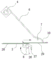
Fig. 1 is a schematic structural view of an embodiment of the present utility model.
Fig. 2 is a schematic diagram of an operating state of an embodiment of the present utility model.
Fig. 3 is a schematic view of the installation position of the pressing blade in the embodiment of the present utility model.
Fig. 4 is a schematic structural view of a pressing mechanism according to an embodiment of the present utility model.
Fig. 5 to 13 are schematic views illustrating the operation of the front-rear hemming mechanism according to the embodiment of the present utility model.
Fig. 14 is a schematic view of a mouse sticking board without hemming in the embodiment of the utility model.
Detailed Description
As shown in fig. 1 and 2, a front-back flanging mechanism of a mouse sticking board comprises a frame 1, a conveying mechanism for conveying the mouse sticking board in the front-back direction is arranged on the frame 1, the conveying mechanism comprises a conveying belt 2 and a conveying belt driving mechanism for driving the conveying belt 2 to move, the conveying belt driving mechanism comprises two rotating rollers 35 rotatably arranged at the front end and the rear end of the frame, one rotating roller 35 is in transmission connection with a driving motor, a front flanging position 3 for carrying out front side flanging and rear side flanging is arranged on the frame 1, a front flanging mechanism and a rear flanging mechanism are arranged on the frame and positioned on the front flanging position 3, the front flanging mechanism comprises a cross rod 4 fixedly arranged above the conveying belt, a rotating cylinder 5 is rotatably arranged on the cross rod 4, a swinging rod 6 is fixedly arranged on the rotating cylinder 5, the rear side surface of the lower part of the swinging rod 6 is fixedly provided with a flanging protrusion 7 which blocks the front side edge and enables the front side edge to be folded upwards, the rear end of the swinging rod is higher than the front end in the embodiment, the front end of the flanging protrusion upper surface 36 is higher than the rear end, so that the front side edge can be folded upwards when moving along the flanging protrusion upper surface, the rear side flanging mechanism comprises a rotating shaft 26 positioned below the conveying belt 2, the rotating shaft 26 is rotatably arranged on the frame 1, a rotating shaft rotation driving mechanism is arranged between the rotating shaft 26 and the frame 1 and comprises a motor, the motor is connected with the rotating shaft 26 in a belt transmission manner, a flanging rotating block 8 is fixedly arranged on the rotating shaft 26, the rotating end of the flanging rotating block 8 is fixedly provided with a flanging press block 9, an edge accommodating groove 27 is arranged between the flanging press 9 and the flanging rotary block 8. The flanging press 9 generates a force for turning the rear side 31 forward along with the rotation of the flanging rotary block 8, and the flanging rotary block has a non-working position, as shown in fig. 5 to 7, in the above figures, the flanging rotary block 8 is in the non-working position, and at this time, the flanging rotary block 8 is located below the conveyor belt 2, so that the flanging rotary block 8 can not block the conveyor belt 2 from conveying the mouse sticking plate. The frame 1 is also provided with a pressing mechanism for pressing the mouse sticking plate when the front side edge folding mechanism and the rear side edge folding mechanism are used for folding; and the swing control mechanism is used for controlling the swing rod 6 to swing. The swing control mechanism controls the swing of the swing rod, so that the folding protrusion 7 is prevented from being clamped on the folded rear side edge, and smooth folding of the rear side edge of the mouse sticking plate is ensured. It should be noted that the front side 30, the rear side 31, the left side 32, and the right side 33 of the mouse sticking board 29 for folding the front side and the rear side in this embodiment have been pressed to complete the folding impression 34. The front side edge and the rear side edge are folded at the front and rear edge folding positions, so that the equipment length is efficiently utilized, the occupation of the processing operation space on the equipment is effectively reduced, the occupied area is small, the structure is compact, and the processing efficiency is high.
As shown in fig. 5, the swing control mechanism comprises a guide support rod 10 fixedly arranged at the lower end of the swing rod and positioned below the flanging protrusion 7, and a swing reset mechanism is arranged between the swing rod 6 and the cross rod 4. The swing reset mechanism comprises a reset spring 11 arranged between the swing rod 6 and the cross rod 4. After the folding of the front side edge is finished, the swing rod 6 is pushed to swing upwards along with the mouse sticking plate conveyed by the conveying belt, as shown in fig. 7, the guide support rod 10 is pressed down on the upper surface of the mouse sticking plate, along with the conveying of the mouse sticking plate by the conveying belt, the guide support rod 10 generates force for pressing down the front side folding of the mouse sticking plate under the action of the reset spring 11, and after the folding of the rear side edge is finished, the swing rod 6 is pushed to be pressed down on the rear side folding of the finished folding along with the mouse sticking plate conveyed by the conveying belt, so that the front side folding and the rear side folding can be better attached to the upper surface of the mouse sticking plate. And because the setting of guide support pole, when the guide support pole supports at gluey mouse board upper surface in addition, the bellied height of hem is higher than the trailing edge of rolling up, this has just avoided bellied 7 card of hem on the trailing edge of rolling up, has avoided bellied 7 of hem influences the hem operation to glueing the trailing edge of mouse board. After the mouse sticking board passes through the guide supporting rod, the swinging rod swings downwards under the action of the swinging reset mechanism, and the front side edge of the next mouse sticking board is ready for flanging.
As another embodiment of the swing control mechanism, the swing control mechanism includes a rotary drum rotation control mechanism provided between the rotary drum and the frame. The rotary cylinder rotation control mechanism comprises a gear ring fixedly arranged on the rotary cylinder and a servo motor for driving the gear ring to rotate. The swing of the swing rod is controlled by controlling the rotation of the servo motor, so that the folding protrusion 7 can be prevented from being clamped on the folded rear side edge, and the smooth folding of the rear side edge of the mouse sticking plate is ensured.
As shown in fig. 1, 3 and 4, the pressing mechanism includes two vertical plates 12 fixedly installed on the frame 1, the two vertical plates 12 are oppositely arranged and spaced from each other, pressing pieces are installed on inner side surfaces of the two vertical plates 12, the pressing range of the side pressing mechanism includes a first section 13 and a second section 14 spaced from each other, and the front and rear flanging positions 3 are arranged between the first section 13 and the second section 14. Thus, the first section 13 and the second section 14 are separated from each other, so that the phenomenon that the pressing mechanism presses down the mouse sticking plate to cause the front side edge and the rear side edge to be pressed down by the pressing mechanism and the folding edge cannot be completed can be avoided. By providing the front and rear hemming position 3 between the first section 13 and the second section 14, the front and rear hemming position 3 is separated from the first section and the second section, so that the pressing mechanism does not press down on the front side and the rear side of the mouse sticking board when the front side and the rear side are hemmed.
The pressing piece of the first section is a pressing conveyer belt or a pressing wheel, and the pressing piece of the second section is a pressing conveyer belt or a pressing wheel. The pushing conveyer belt or the pushing pinch roller of the pushing mechanism can synchronously move with the conveyer belt through friction force between the pushing conveyer belt or the pushing pinch roller and the conveyer belt, and the corresponding power device can be configured to drive the pushing conveyer belt or the pushing pinch roller so as to synchronously move with the conveyer belt. It should be noted that the push-down conveyor belt is wound around a plurality of guide wheels, which play a role in tensioning and guiding. When the pressing piece of the first section is a pressing conveyer belt, the pressing piece of the second section can be a pressing conveyer belt or a pressing wheel, when the pressing piece of the first section is a pressing wheel, the pressing piece of the second section can be a pressing conveyer belt or a pressing wheel, for example, when the pressing pieces of the first section and the second section are both pressing wheels, the adjacent pressing wheels of the first section and the second section are far away from each other so as to form a front-back edge folding position between the first section and the second section. For another example, when the pressing members of the first section and the second section both adopt pressing conveying belts, the conveying belts of the first section and the second section may have a belt body, that is, the conveying belts of the first section and the conveying belts of the second section are independent of each other, so that the front and rear hemming positions may be formed between the conveying belts of the first section and the second section by setting the distance between the conveying belts of the first section and the conveying belts of the second section.
As shown in fig. 4, it is of course also possible, as used in this embodiment, that the first section 13 and the second section 14 each adopt a pressing conveyer belt as a pressing member, the pressing conveyer belts of the first section and the second section are connected into one, a plurality of guide wheels are rotatably mounted on the inner side surface of the vertical plate, the pressing conveyer belt 15 is sleeved between the guide wheels, the guide wheels include a plurality of lower guide wheels 17 and upper guide wheels 18 rotatably mounted on the inner side surface of the vertical plate 12, an intermediate guide wheel 16 located between two adjacent lower guide wheels 17 and above the lower guide wheels 17 is rotatably mounted on the vertical plate 12, and the pressing conveyer belt winds between the lower guide wheels 17, the upper guide wheels 18 and the intermediate guide wheels 16. The downward pressing conveyer belt 15 which passes through the middle guide wheel 16 is upwards far away from the conveyer belt so as to form an upward concave part 28, the front and rear edge folding positions 3 correspond to the upward concave part 28, and the upward concave part is upwards far away from the conveyer belt, so that the phenomenon that the front side edge and the rear side edge cannot be folded due to the downward pressing of the mouse sticking plate by the downward pressing mechanism when the front and rear side edge folding is carried out is avoided.
With the conveying of the mouse sticking plate by the conveying belt, as shown in fig. 5, the front side edge of the mouse sticking plate is in contact with the flanging bulge 7, as shown in fig. 6 and 7, the front side edge is upwards turned under the action of the flanging bulge 7, as shown in fig. 4, the upward concave portion 28 is arranged to enable the downward pressing conveying belt not to block the upward turning of the front side edge, the upwards turned mouse sticking plate is continuously conveyed by the conveying belt, the mouse sticking plate is conveyed between the downward pressing conveying belt and the conveying belt 2, so that two ends of the front side edge are pressed on the upper surface of the mouse sticking plate, when the rear side edge of the mouse sticking plate moves to the position above the flanging press block 9, the rotating shaft 26 rotates, as shown in fig. 8 to 9, so that the flanging press block 8 rotates upwards to drive the rear side edge of the mouse sticking plate to be upwards turned, and with the continuous rotation of the flanging press block, as shown in fig. 10 to 13, so that the rear side edge is pressed on the upper surface of the mouse sticking plate.
The two conveyer belts 2 are arranged side by side, a gap 19 is arranged between the two conveyer belts 2, and the swinging rod 6 and the flanging rotating block 8 are positioned between the two conveyer belts.
The frame is also fixedly provided with a supporting plate 20 which is supported on the lower surface of the conveying belt 2, and the supporting plate is provided with an opening 21 for the guide supporting rod 10 to fall down and the rotating end of the flanging rotating block to rotate out.
In this embodiment, install two on the axis of rotation hem turning block 8, two contained angle is one hundred eighty degrees between the hem turning block 8, like this after one the operation is accomplished to hem turning block 8, the axis of rotation can rotate one hundred eighty degrees after, makes another the hem turning block accomplish the hem operation, has improved work efficiency.
The pressing mechanism further comprises a rear pressing mechanism positioned behind the front side edge folding mechanism and the rear side edge folding mechanism, the rear pressing mechanism comprises a pressing knife 22 arranged on the frame, and the pressing knife 22 is positioned between the two vertical plates.
The foregoing has shown and described the basic principles and main features of the present utility model and the advantages of the present utility model. It will be understood by those skilled in the art that the present utility model is not limited to the embodiments described above, and that the above embodiments and descriptions are merely illustrative of the principles of the present utility model, and various changes and modifications may be made without departing from the spirit and scope of the utility model, which is defined in the appended claims. The scope of the utility model is defined by the appended claims and equivalents thereof.
Claims (10)
1. The utility model provides a glue mouse board and incline mechanism around, includes the frame, install on the frame and carry out the conveying mechanism who carries out fore-and-aft direction to glue mouse board, conveying mechanism includes conveyer belt and drive conveyer belt actuating mechanism that the conveyer belt removed, its characterized in that, be equipped with the front and back hem position that carries out front side and back side hem on the frame, be equipped with in the frame and be located front and back hem position side hem mechanism and back side hem mechanism, front side hem mechanism includes the horizontal pole of fixed mounting in the conveyer belt top, rotate on the horizontal pole and install the rotary drum, fixed mounting has the swinging arms on the rotary drum, the rear side surface fixed mounting of the lower part of swinging arms blocks the front side and makes the hem arch of front side upwards turn over, back side hem mechanism includes being located the axis of rotation below the conveyer belt, the axis of rotation is installed in the frame, fixed mounting has the hem turning block on the axis of rotation, the fixed setting has the hem briquetting on the turning end of hem turning block, the hem turning block has non-work station when the side edge mechanism is carried out to press down in the conveyer belt, the side hem mechanism is pressed down in the frame; the swing control mechanism is used for controlling the swing rod to swing.
2. The mouse sticking board front-rear hemming mechanism according to claim 1, wherein: and an edge accommodating groove for accommodating the rear side edge of the mouse sticking plate is formed between the edge folding pressing block and the edge folding rotating block.
3. The mouse sticking board front-rear hemming mechanism according to claim 1, wherein: the swing control mechanism comprises a guide supporting rod fixedly arranged at the lower end of the swing rod and positioned below the flanging bulge, and a swing reset mechanism is arranged between the swing rod and the cross rod; alternatively, the swing control mechanism includes a rotary drum rotation control mechanism provided between the rotary drum and the frame.
4. The mouse sticking board front-rear hemming mechanism according to claim 2, wherein: the pushing mechanism comprises two vertical plates fixedly installed on the frame, the two vertical plates are oppositely arranged and spaced, a pushing piece is installed on the inner side surface of each vertical plate, the pushing range of the side pushing mechanism comprises a first section and a second section which are spaced from each other, and a front folding edge and a rear folding edge are arranged between the first section and the second section.
5. The mouse sticking board front-rear hemming mechanism of claim 4 wherein: the pressing piece of the first section is a pressing conveyer belt or a pressing wheel, and the pressing piece of the second section is a pressing conveyer belt or a pressing wheel.
6. The mouse sticking board front-rear hemming mechanism of claim 5 wherein: the first section and the second section all adopt the conveyer belt that pushes down as the casting die, the conveyer belt that pushes down of first section is connected to one with the conveyer belt that pushes down of second section, the inboard surface rotation of vertical board is installed a plurality of leading wheels, the cover has between the leading wheel the conveyer belt that pushes down, the leading wheel includes a plurality of leading wheels and the last leading wheel of the inboard surface rotation installation of vertical board, rotate on the vertical board and install and be located adjacent two between the leading wheel down and be located the intermediate guide wheel of leading wheel top down, the conveyer belt that pushes down the warp down the leading wheel down with between the intermediate guide wheel, the warp intermediate guide wheel push down the conveyer belt upwards and keep away from thereby form the upper concave part, the hem position with the upper concave part corresponds.
7. The mouse sticking board front-rear hemming mechanism of claim 6 wherein: the two conveyer belts are arranged side by side, a gap is arranged between the two conveyer belts, and the swinging rod and the flanging rotating block are positioned between the two conveyer belts.
8. A mouse sticking board front-rear hemming mechanism according to claim 3 wherein: the frame is also fixedly provided with a supporting plate, the supporting plate is supported on the lower surface of the conveying belt, and the supporting plate is provided with an opening for the guide supporting rod to fall down and the rotating end of the flanging rotating block to rotate out.
9. The mouse sticking board front-rear hemming mechanism according to claim 1, wherein: two hem rotating blocks are arranged on the rotating shaft, and an included angle between the two hem rotating blocks is one hundred eighty degrees.
10. The mouse sticking board front-rear hemming mechanism of claim 4 wherein: the pressing mechanism further comprises a rear pressing mechanism positioned behind the front side edge folding mechanism and the rear side edge folding mechanism, the rear pressing mechanism comprises a pressing knife arranged on the frame, and the pressing knife is positioned between the two vertical plates.
Priority Applications (1)
| Application Number | Priority Date | Filing Date | Title |
|---|---|---|---|
| CN202222415144.6U CN219338741U (en) | 2022-09-13 | 2022-09-13 | Mechanism for folding mouse sticking plate back and forth |
Applications Claiming Priority (1)
| Application Number | Priority Date | Filing Date | Title |
|---|---|---|---|
| CN202222415144.6U CN219338741U (en) | 2022-09-13 | 2022-09-13 | Mechanism for folding mouse sticking plate back and forth |
Publications (1)
| Publication Number | Publication Date |
|---|---|
| CN219338741U true CN219338741U (en) | 2023-07-14 |
Family
ID=87104586
Family Applications (1)
| Application Number | Title | Priority Date | Filing Date |
|---|---|---|---|
| CN202222415144.6U Active CN219338741U (en) | 2022-09-13 | 2022-09-13 | Mechanism for folding mouse sticking plate back and forth |
Country Status (1)
| Country | Link |
|---|---|
| CN (1) | CN219338741U (en) |
-
2022
- 2022-09-13 CN CN202222415144.6U patent/CN219338741U/en active Active
Similar Documents
| Publication | Publication Date | Title |
|---|---|---|
| CN107042555A (en) | A kind of automatic scar removing machine for timbers | |
| CN219338741U (en) | Mechanism for folding mouse sticking plate back and forth | |
| CN112265356B (en) | Flatting mill is used in material printing | |
| CN210929372U (en) | Flour sheet roll machine | |
| CN110711811A (en) | Edge folding machine for rolling circle | |
| CN116728879A (en) | Paperboard bending and forming device | |
| CN110641144A (en) | Double-sided printing folding device for hand bag | |
| CN201143802Y (en) | Automatic folding book-binding machine | |
| CN201385800Y (en) | Conveyor capable of automatically stacking stuff | |
| CN116141756A (en) | Edge folding machine for mouse sticking plate production | |
| CN112811215A (en) | Paper feeding and feeding device of paperboard printing machine | |
| CN220766014U (en) | Guiding mechanism is used in printed matter printing | |
| CN219618701U (en) | Steel wire rolling device of rotary machine | |
| CN216996907U (en) | Foil pressing wheel of gilding press | |
| CN213350531U (en) | Coiled material feeding side feeding device | |
| CN219236338U (en) | Secondary folding mechanism for automatic handbag folding production line | |
| CN217742933U (en) | Automatic spring roll forming machine | |
| CN218201409U (en) | A interior seventy percent discount device for gauze pad production | |
| CN220484884U (en) | Folding mechanism | |
| CN215854204U (en) | Material storing and discharging device for elastic non-woven fabric compounding machine | |
| CN110001186A (en) | Printing roller of flexible printing machine pressure-regulating device | |
| CN217346585U (en) | Discharging traction mechanism for three-layer co-extrusion PE foaming sheet production line | |
| CN212422612U (en) | Book flattening device | |
| CN215885766U (en) | Paper pressing device with quick adjustment function | |
| CN220810904U (en) | Automatic plate feeding mechanism |
Legal Events
| Date | Code | Title | Description |
|---|---|---|---|
| GR01 | Patent grant | ||
| GR01 | Patent grant |