CN219337099U - Novel grinding machine for wall construction - Google Patents
Novel grinding machine for wall construction Download PDFInfo
- Publication number
- CN219337099U CN219337099U CN202320608358.7U CN202320608358U CN219337099U CN 219337099 U CN219337099 U CN 219337099U CN 202320608358 U CN202320608358 U CN 202320608358U CN 219337099 U CN219337099 U CN 219337099U
- Authority
- CN
- China
- Prior art keywords
- base
- screw rod
- motor
- grinding machine
- dust
- Prior art date
- Legal status (The legal status is an assumption and is not a legal conclusion. Google has not performed a legal analysis and makes no representation as to the accuracy of the status listed.)
- Active
Links
Images
Classifications
-
- Y—GENERAL TAGGING OF NEW TECHNOLOGICAL DEVELOPMENTS; GENERAL TAGGING OF CROSS-SECTIONAL TECHNOLOGIES SPANNING OVER SEVERAL SECTIONS OF THE IPC; TECHNICAL SUBJECTS COVERED BY FORMER USPC CROSS-REFERENCE ART COLLECTIONS [XRACs] AND DIGESTS
- Y02—TECHNOLOGIES OR APPLICATIONS FOR MITIGATION OR ADAPTATION AGAINST CLIMATE CHANGE
- Y02P—CLIMATE CHANGE MITIGATION TECHNOLOGIES IN THE PRODUCTION OR PROCESSING OF GOODS
- Y02P70/00—Climate change mitigation technologies in the production process for final industrial or consumer products
- Y02P70/10—Greenhouse gas [GHG] capture, material saving, heat recovery or other energy efficient measures, e.g. motor control, characterised by manufacturing processes, e.g. for rolling metal or metal working
Abstract
The utility model discloses a novel grinding machine for wall construction, which comprises a base, wherein a controller and a mobile power supply are embedded on the base, an adjusting component is arranged at the upper end of the base and comprises a cross rod, a guide rod and a first screw rod, the guide rod and the first screw rod are rotatably arranged at the upper end of the base, the cross rod is sleeved on the guide rod and is sleeved on the first screw rod in a threaded manner, a first motor at one side of the base is connected with the first screw rod, a second screw rod is rotationally arranged in a guide frame at one end of the cross rod, a second motor at the upper end of the guide frame is connected with the second screw rod, a connecting seat is sleeved on the second screw rod in a threaded manner, a grinding machine body is arranged on the connecting seat, and the grinding machine body, the first motor and the second motor are electrically connected with the mobile power supply through the controller. Can drive polisher body at uniform velocity horizontal and vertical movement through first screw rod and second screw rod rotation, control the travel speed of polisher body and the dynamics of polishing are convenient, improve the efficiency of grinding the wall, and do not need constructor to hold, convenient to use is laborsaving.
Description
Technical Field
The utility model relates to the technical field of wall construction, in particular to a novel grinding machine for wall construction.
Background
The main function of the putty is leveling, but only half of leveling work is performed when the putty is only leveling, and the other half of the putty is half of the final effect, so that the problem is solved by polishing, the final flatness of the wall is related to the wall polishing, and meanwhile, the putty is an important means for solving some minor flaws in wall decoration.
At present, when using the polisher to polish the wall, most constructors hold the polisher to polish the wall, but the operation mode of handheld polisher polishing the wall has not only increased constructor's intensity of labour and the polisher is difficult for controlling at the travel speed and the dynamics of polishing of wall to lead to the wall efficiency of polishing slowly, consequently, proposes a novel mill of wall construction and solves above technical problem.
Disclosure of Invention
The utility model aims to provide a novel wall surface construction grinding machine, which can effectively solve the problems.
The aim of the utility model can be achieved by the following technical scheme:
the utility model provides a novel mill of wall construction, includes the base, inlay on the base and be equipped with controller and portable power source, the upper end of base is equipped with adjusting part, adjusting part includes horizontal pole, guide bar and first screw rod, the guide bar with first screw rod rotates and sets up in the first mounting groove of base upper end, the horizontal pole cover is established on the guide bar and the thread bush is established on the first screw rod, be fixed with first motor through the bolt fastening in the first mount of base one side, first motor pass through the shaft coupling with first screw rod is connected, the fixed leading truck rotation that sets up of horizontal pole one end is provided with the second screw rod, be fixed with the second motor through the bolt fastening in the second mount of guide bar upper end, the second motor pass through the shaft coupling with second screw rod is connected, the thread bush is equipped with the connecting seat on the second screw rod, be fixed with the polisher body through the bolt fastening in the third mount of connecting seat one side, the first motor with the second motor all passes through the controller with the portable power source is connected.
Further, the dust collection assembly is sleeved on the polisher body and comprises a dust collector body, a collecting box and a dust collection cover, the dust collector body is fixed in a placing groove in the base through bolts, the collecting box is arranged in the placing groove in a sliding mode, a dust exhaust pipe on the dust collector body is arranged in the collecting box in a penetrating mode, the dust collection cover is arranged on the third fixing frame and is sleeved on the polisher body, the dust collection pipe on the dust collector body is sleeved on a connecting port on the dust collection cover, and the dust collector body is electrically connected with the mobile power supply through the controller.
Further, two groups of connecting shafts are uniformly and fixedly arranged at one end of the dust hood, two groups of connecting plates are uniformly and fixedly arranged at the periphery of the third fixing frame, the connecting shafts penetrate through the connecting plates and are limited by the limiting knob, springs are sleeved on the connecting shafts, and two ends of each spring respectively support against the dust hood and the connecting plates.
Further, the opening part of the placing groove is fixedly provided with a magnet, two sides of the collecting box are fixedly provided with magnetic attraction blocks, and the magnetic attraction blocks are matched with the magnet.
Further, a handle is fixedly arranged on one side of the collecting box, and one end of the dust hood is sleeved with a smooth anti-abrasion ring.
Further, two groups of second mounting grooves are respectively formed in two sides of the lower end of the base, electric telescopic rods are fixed in the second mounting grooves through bolts, mounting rods are fixed at the telescopic ends of the electric telescopic rods through bolts, the mounting rods are slidably clamped in the second mounting grooves, universal wheels are respectively and fixedly arranged at two ends of the mounting rods, and the electric telescopic rods are electrically connected with the mobile power supply through the controller.
Further, the lower extreme bonding of base is fixed with the slipmat, the upper end of base is provided with the protective cover, the protective cover shelter from first mounting groove and with one side of base is articulated.
The utility model has the beneficial effects that:
the grinding machine comprises a grinding machine body, a first motor and a second motor, wherein the grinding machine body is started by a controller, the wall surface can be ground to be flat, the first motor is started to drive a first screw to rotate, the first screw rotates to enable a cross rod to horizontally move along the first screw in a threaded fit manner, the cross rod horizontally moves to drive the grinding machine body to horizontally move through a guide frame and a connecting seat, the wall surface is ground at a uniform speed along the horizontal direction, the second motor is started to drive a second screw to rotate, the connecting seat is enabled to move along the second screw in a threaded fit manner by the second screw, the connecting seat is moved to drive the grinding machine body to move along the vertical direction, the wall surface is ground at a uniform speed along the vertical direction, the moving speed and the grinding force of the grinding machine body are controlled to be convenient, the efficiency of grinding the wall surface is improved, constructor is not required to hold the grinding machine body, and the use is convenient and labor-saving.
Can cover the dust that produces when polishing the wall with the polisher body through setting up the dust hood, then start the dust catcher body through the controller, the dust catcher body can be through the dust absorption of dust absorption pipe in with the dust hood and in collecting the box is got into through the dust exhaust pipe row, and it is convenient to collect the dust, avoids producing the in-process of polishing the wall and causes harm to constructor's health, improves the security that the device used.
The two sets of electric telescopic rods are controlled by the controller to extend, the two sets of mounting rods can drive the four sets of universal wheels to move downwards and jack up the base reversely to separate the base from the ground, at the moment, the universal wheels can be used for moving the device, the moving device is convenient and labor-saving, the base can be fixed with the ground by means of contact of the base again through the shrinkage of the two sets of electric telescopic rods controlled by the controller, and the fixing device is convenient.
Drawings
The utility model is further described below with reference to the accompanying drawings.
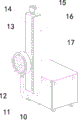
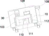
FIG. 1 is a schematic perspective view of the present utility model;
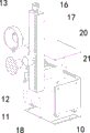
FIG. 2 is an exploded view of the present utility model;
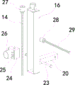
FIG. 3 is an exploded view of the conditioning assembly of the present utility model;
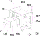
FIG. 4 is an exploded view of the base of the present utility model, partially in section;
FIG. 5 is a schematic perspective view of a base of the present utility model;
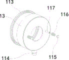
fig. 6 is an exploded view of the suction hood of the present utility model.
In the figure, the correspondence between the component names and the drawing numbers is:
10. a base; 11. a dust collection pipe; 12. a sander body; 13. a dust hood; 14. a second screw; 15. the second fixing frame; 16. a guide frame; 17. a protective cover; 18. an anti-slip pad; 20. a cross bar; 21. a first mounting groove; 23. a guide rod; 24. a connecting seat; 25. a connecting plate; 26. a third fixing frame; 27. a second motor; 28. a first motor; 29. a first screw; 30. a controller; 31. a handle; 101. a magnetic suction block; 102. a collection box; 103. a placement groove; 104. a mounting rod; 105. a universal wheel; 106. an electric telescopic rod; 107. a second mounting groove; 108. a first fixing frame; 109. a mobile power supply; 110. a dust exhaust pipe; 111. a cleaner body; 112. a magnet; 113. an anti-wear ring; 114. a connection port; 115. a limit knob; 116. a spring; 117. and a connecting shaft.
Detailed Description
The technical solutions in the embodiments of the present utility model will be clearly and completely described below with reference to the accompanying drawings in the embodiments of the present utility model.
Examples
As shown in fig. 1 to 4, a novel grinding machine for wall construction comprises a base 10, a controller 30 and a mobile power supply 109 are embedded on the base 10, an adjusting component is arranged at the upper end of the base 10 and comprises a cross rod 20, a guide rod 23 and a first screw 29, the guide rod 23 and the first screw 29 are rotatably arranged in a first mounting groove 21 at the upper end of the base 10, the cross rod 20 is sleeved on the guide rod 23 and is sleeved on the first screw 29 in a threaded manner, a first motor 28 is fixed in a first fixing frame 108 at one side of the base 10 through bolts, the first motor 28 is connected with the first screw 29 through a coupler, a second motor 27 is rotationally arranged in a guide frame 16 fixedly arranged at one end of the cross rod 20, the second motor 27 is connected with the second screw 14 through a coupler, a connecting seat 24 is sleeved on the second screw 14 through a threaded manner, a third fixing frame 26 at one side of the connecting seat 24 is fixedly provided with a grinding machine body 12 through bolts, and the grinding machine body 12, the first motor 28 and the second motor 27 are electrically connected with the mobile power supply 109 through the controller 30.
During the use, through removing base 10 to one side of wall, and make polisher body 12 and wall contact, then start polisher body 12 through controller 30, first motor 28 and second motor 27, the polisher body 12 starts and can polish the wall, first motor 28 starts and drives first screw rod 29 rotation, first screw rod 29 rotates and horizontal pole 20 screw-thread fit makes horizontal pole 20 follow first screw rod 29 horizontal migration, horizontal pole 20 horizontal migration passes through leading truck 16 and connecting seat 24 drive polisher body 12 horizontal migration, thereby polish the wall at the uniform velocity along the horizontal direction, second motor 27 starts and drives second screw rod 14 rotation, second screw rod 14 rotates and connecting seat 24 screw-thread fit makes connecting seat 24 follow second screw rod 14 removal, connecting seat 24 removes and drives polisher body 12 along the vertical direction, thereby polish the wall at the uniform velocity along the vertical direction, it is convenient to drive polisher body 12 horizontal and vertical direction removal through the uniform velocity, it is convenient to control the travel speed of polisher body 12 and the dynamics of polishing, improve the efficiency of polishing the wall, and need not the constructor hold polisher body 12, convenient to use, polisher body 12 comprises motor and polishing disk.
Referring to fig. 2, 3, 5 and 6, the grinding machine body 12 is sleeved with a dust collection assembly, the dust collection assembly comprises a dust collector body 111, a collection box 102 and a dust collection cover 13, the dust collector body 111 is fixed in a placing groove 103 in the base 10 through bolts, the collection box 102 is slidably arranged in the placing groove 103, a dust exhaust pipe 110 on the dust collector body 111 is arranged in the collection box 102 in a penetrating mode, the dust collection cover 13 is arranged on a third fixing frame 26 and is sleeved on the grinding machine body 12, a dust collection pipe 11 on the dust collector body 111 is sleeved on a connection port 114 on the dust collection cover 13, and the dust collector body 111 is electrically connected with a mobile power supply 109 through a controller 30.
Can cover the dust that produces when polishing the wall with polisher body 12 through setting up suction hood 13, then start dust catcher body 111 through controller 30, dust catcher body 111 can be through the dust absorption of dust absorption pipe 11 in with suction hood 13 and in collecting box 102 is got into through dust exhaust pipe 110, it is convenient to collect the dust, avoids producing the in-process of polishing the wall and causes harm to constructor's health, improves the security that the device used, and the model of dust catcher body 111 is YLC6280.
Referring to fig. 3 and 6, two groups of connecting shafts 117 are uniformly and fixedly arranged at one end of the dust hood 13, two groups of connecting plates 25 are uniformly and fixedly arranged at the periphery of the third fixing frame 26, the connecting shafts 117 penetrate through the connecting plates 25 and are limited by the limiting knob 115, springs 116 are sleeved on the connecting shafts 117, two ends of each spring 116 respectively support against the dust hood 13 and the connecting plates 25, and the dust hood 13 can be ensured to be always contacted with the wall surface by arranging the springs 116 to support against the dust hood 13, so that the effect of collecting dust is improved.
Referring to fig. 4 to 6, the magnets 112 are fixedly arranged at the openings of the placing grooves 103, the magnetic attraction blocks 101 are fixedly arranged at two sides of the collecting box 102, the magnetic attraction blocks 101 are matched with the magnets 112, the collecting box 102 is convenient to fix, the handles 31 are fixedly arranged at one side of the collecting box 102, the collecting box 102 is convenient to take, a smooth anti-abrasion ring 113 is sleeved at one end of the dust hood 13, abrasion damage of the dust hood 13 is avoided, meanwhile, friction force between the dust hood 13 and a wall surface is reduced, the wall surface is prevented from being scratched, the service life of the dust hood 13 is prolonged, the anti-abrasion ring 113 is connected with the dust hood 13 in a clamping manner, and the wearing part anti-abrasion ring 113 is convenient to replace.
Referring to fig. 4, two sets of second mounting grooves 107 are respectively formed on two sides of the lower end of the base 10, electric telescopic rods 106 are fixed in the two sets of second mounting grooves 107 through bolts, mounting rods 104 are fixed at telescopic ends of the electric telescopic rods 106 through bolts, the mounting rods 104 are slidably clamped in the second mounting grooves 107, universal wheels 105 are respectively fixedly arranged at two ends of the mounting rods 104, the two sets of electric telescopic rods 106 are electrically connected with a mobile power supply 109 through a controller 30, the two sets of electric telescopic rods 106 are controlled by the controller 30 to extend, the two sets of mounting rods 104 can drive four sets of universal wheels 105 to move downwards and jack up the base 10 reversely to separate the base 10 from the ground, at this time, the universal wheels 105 can be used for moving the device, the moving device is convenient and labor-saving, the base 10 can be fixed with the ground by controlling the two sets of electric telescopic rods 106 to shrink again, and the fixing device is convenient.
Referring to fig. 2 and 3, the anti-slip pad 18 is fixedly adhered to the lower end of the base 10, so that the stability of the base 10 fixed on the ground is improved, the sliding phenomenon is avoided, the protective cover 17 is arranged at the upper end of the base 10, the protective cover 17 shields the first mounting groove 21 and is hinged to one side of the base 10, the damage to constructors can be avoided by arranging the protective cover 17 through the first screw 29 which rotates, the protective cover 17 is hinged, the protective cover 17 is conveniently opened and closed, the overhaul of the components in the first mounting groove 21 is facilitated, and the overhaul device is convenient.
The working principle of the utility model is as follows: through four sets of universal wheels 105 that set up remove base 10 to one side of wall and make polisher body 12 and wall contact and the wear ring 113 on the suction hood 13 contact with the wall, then control two sets of electric telescopic handle 106 shrink through controller 30 and make installation pole 104 upwards remove and drive universal wheel 105 retract in the second mounting groove 107, this moment base 10 is fixed with ground contact pair device, the rethread controller 30 of fixed device back starts polisher body 12, first motor 28, second motor 27 and dust catcher body 111, polisher body 12 start can polish the wall, first motor 28 starts and drives first screw 29 rotation, first screw 29 rotates and horizontal pole 20 screw thread cooperation makes horizontal pole 20 follow first screw 29 horizontal migration, horizontal pole 20 horizontal migration drives polisher body 12 horizontal migration through leading truck 16 and connecting seat 24, thereby polish the wall at the uniform velocity along the horizontal direction, second motor 27 starts and drives second screw 14 rotation, second screw 14 rotates and connecting seat 24 screw 14 removal, connecting seat 24 removes and drives polisher body 12 along the vertical direction, thereby it is along the vertical direction to polish the polisher body 12, the horizontal velocity is convenient to take the polisher body 12, and the horizontal velocity is controlled to the horizontal velocity is not used to the polishing, the wall is convenient to carry out, the polishing speed is convenient to the wall is carried out with the horizontal velocity of the polisher body 12.
Claims (7)
1. Novel mill of wall construction, its characterized in that: including base (10), inlay on base (10) and be equipped with controller (30) and portable power source (109), the upper end of base (10) is equipped with adjusting part, adjusting part includes horizontal pole (20), guide bar (23) and first screw rod (29), guide bar (23) with first screw rod (29) rotate and set up in first mounting groove (21) of base (10) upper end, horizontal pole (20) cover is established on guide bar (23) and thread bush is established on first screw rod (29), be equipped with first motor (28) through the bolt fastening in first mount (108) of base (10) one side, first motor (28) pass through the shaft coupling with first screw rod (29) are connected, the leading truck (16) one end internal rotation that horizontal pole (20) set up is provided with second screw rod (14), be equipped with second motor (27) through the bolt fastening in second mount (15) of leading truck (16) upper end, second motor (27) are established on guide bar (23) and thread bush is in first screw rod (29), first motor (28) are equipped with through the shaft coupling with second screw rod (29) connection seat (24), screw rod (24) are equipped with on one side of the screw rod (12) connection seat (12) The first motor (28) and the second motor (27) are electrically connected with the mobile power supply (109) through the controller (30).
2. The novel wall construction grinding machine according to claim 1, wherein: the dust collection device is characterized in that a dust collection assembly is sleeved on the grinding machine body (12), the dust collection assembly comprises a dust collector body (111), a collection box (102) and a dust collection cover (13), the dust collector body (111) is fixed in a placing groove (103) in the base (10) through bolts, the collection box (102) is arranged in the placing groove (103) in a sliding mode, a dust exhaust pipe (110) on the dust collector body (111) is arranged in the collection box (102) in a penetrating mode, the dust collection cover (13) is arranged on a third fixing frame (26) and is sleeved on the grinding machine body (12), a dust collection pipe (11) on the dust collection body (111) is sleeved on a connecting port (114) on the dust collection cover (13), and the dust collector body (111) is electrically connected with a mobile power supply (109) through a controller (30).
3. The novel wall construction grinding machine according to claim 2, wherein: two groups of connecting shafts (117) are uniformly and fixedly arranged at one end of the dust hood (13), two groups of connecting plates (25) are uniformly and fixedly arranged on the periphery of the third fixing frame (26), the connecting shafts (117) penetrate through the connecting plates (25) and are limited by limiting knobs (115), springs (116) are sleeved on the connecting shafts (117), and two ends of each spring (116) respectively prop against the dust hood (13) and the connecting plates (25).
4. A novel wall construction grinding machine according to claim 3, characterized in that: the magnet (112) is fixedly arranged at the opening of the placing groove (103), the magnetic attraction blocks (101) are fixedly arranged on two sides of the collecting box (102), and the magnetic attraction blocks (101) are matched with the magnet (112).
5. A novel wall construction grinding machine according to claim 3, characterized in that: one side of the collecting box (102) is fixedly provided with a handle (31), and one end of the dust hood (13) is sleeved with a smooth anti-abrasion ring (113).
6. The novel wall construction grinding machine according to claim 1, wherein: two groups of second mounting grooves (107) are respectively formed in two sides of the lower end of the base (10), electric telescopic rods (106) are fixed in the second mounting grooves (107) through bolts, mounting rods (104) are fixed at telescopic ends of the electric telescopic rods (106) through bolts, the mounting rods (104) are slidably clamped in the second mounting grooves (107), universal wheels (105) are respectively and fixedly arranged at two ends of the mounting rods (104), and the electric telescopic rods (106) are electrically connected with a mobile power supply (109) through the controller (30).
7. The novel wall construction grinding machine according to claim 6, wherein: the anti-slip mat (18) is fixedly adhered to the lower end of the base (10), a protective cover (17) is arranged at the upper end of the base (10), and the protective cover (17) shields the first mounting groove (21) and is hinged to one side of the base (10).
Priority Applications (1)
| Application Number | Priority Date | Filing Date | Title |
|---|---|---|---|
| CN202320608358.7U CN219337099U (en) | 2023-03-25 | 2023-03-25 | Novel grinding machine for wall construction |
Applications Claiming Priority (1)
| Application Number | Priority Date | Filing Date | Title |
|---|---|---|---|
| CN202320608358.7U CN219337099U (en) | 2023-03-25 | 2023-03-25 | Novel grinding machine for wall construction |
Publications (1)
| Publication Number | Publication Date |
|---|---|
| CN219337099U true CN219337099U (en) | 2023-07-14 |
Family
ID=87078128
Family Applications (1)
| Application Number | Title | Priority Date | Filing Date |
|---|---|---|---|
| CN202320608358.7U Active CN219337099U (en) | 2023-03-25 | 2023-03-25 | Novel grinding machine for wall construction |
Country Status (1)
| Country | Link |
|---|---|
| CN (1) | CN219337099U (en) |
-
2023
- 2023-03-25 CN CN202320608358.7U patent/CN219337099U/en active Active
Similar Documents
| Publication | Publication Date | Title |
|---|---|---|
| CN212470835U (en) | Sample grinding mechanism for casting | |
| CN219337099U (en) | Novel grinding machine for wall construction | |
| CN220178982U (en) | Brake block abrasive machining equipment | |
| CN210255421U (en) | Adjustable cylindrical grinding machine | |
| CN208067984U (en) | A kind of production elevator counterweight block grinding mechanism | |
| CN212553172U (en) | Semi-automatic axle core polisher | |
| CN212977690U (en) | Plate polishing device for elevator car | |
| CN220408317U (en) | Bearing outer ring inner wall grinding device | |
| CN219853874U (en) | Can guarantee burnishing machine of operational environment quality | |
| CN217167999U (en) | Mechanical surface polishing tool for large steel part | |
| CN212399087U (en) | Closed automatic polisher of ironcasting | |
| CN220718740U (en) | Operation panel is used in paper corner protector processing | |
| CN216178989U (en) | GN5 piston surface smoothing equipment | |
| CN220463266U (en) | Efficient polishing device | |
| CN218697282U (en) | Grinding machine with dust removal and environmental protection functions | |
| CN214869495U (en) | Office furniture corner polishing mechanism | |
| CN218874958U (en) | Polishing machine for machining | |
| CN216327388U (en) | Grinding device is used in heavy-duty car draw beam ADI part processing | |
| CN220825747U (en) | Terrace grinds machine | |
| CN219684939U (en) | Grinding equipment for machining mechanical parts | |
| CN214771118U (en) | A joint grinding device for production of wooden image | |
| CN212496875U (en) | Interior wall grinds paper-back edition and puts for housing construction of waste material can be got | |
| CN220446176U (en) | Polishing mechanism for polishing machine | |
| CN215659383U (en) | Deburring device for pre-buried channel mechanism | |
| CN216657432U (en) | Switch is wearing and tearing machine for apron |
Legal Events
| Date | Code | Title | Description |
|---|---|---|---|
| GR01 | Patent grant | ||
| GR01 | Patent grant |