CN219304435U - Wedge-shaped strain clamp - Google Patents
Wedge-shaped strain clamp Download PDFInfo
- Publication number
- CN219304435U CN219304435U CN202320472170.4U CN202320472170U CN219304435U CN 219304435 U CN219304435 U CN 219304435U CN 202320472170 U CN202320472170 U CN 202320472170U CN 219304435 U CN219304435 U CN 219304435U
- Authority
- CN
- China
- Prior art keywords
- insulating core
- wire
- hanging plate
- clamp
- wire clamp
- Prior art date
- Legal status (The legal status is an assumption and is not a legal conclusion. Google has not performed a legal analysis and makes no representation as to the accuracy of the status listed.)
- Active
Links
Images


Classifications
-
- Y—GENERAL TAGGING OF NEW TECHNOLOGICAL DEVELOPMENTS; GENERAL TAGGING OF CROSS-SECTIONAL TECHNOLOGIES SPANNING OVER SEVERAL SECTIONS OF THE IPC; TECHNICAL SUBJECTS COVERED BY FORMER USPC CROSS-REFERENCE ART COLLECTIONS [XRACs] AND DIGESTS
- Y02—TECHNOLOGIES OR APPLICATIONS FOR MITIGATION OR ADAPTATION AGAINST CLIMATE CHANGE
- Y02E—REDUCTION OF GREENHOUSE GAS [GHG] EMISSIONS, RELATED TO ENERGY GENERATION, TRANSMISSION OR DISTRIBUTION
- Y02E10/00—Energy generation through renewable energy sources
- Y02E10/50—Photovoltaic [PV] energy
Abstract
The utility model relates to a wedge-shaped strain clamp. The utility model aims to solve the technical problem of providing a grip-enhancement type wedge-shaped strain clamp with long service life. The wire clamp comprises a wire clamp main body, an upper insulating core, a lower insulating core, an upper hanging plate and a lower hanging plate, wherein one end of the upper hanging plate and one end of the lower hanging plate are connected with the wire clamp main body through connecting bolts, the upper insulating core and the lower insulating core are respectively provided with an insulating core wire clamping groove, a wire clamp inserting opening is arranged in the wire clamp main body, a wire inlet end of the wire clamp main body is provided with a bolt fixing part, a hanging plate positioning step is arranged on the bolt fixing part, and hanging plate sleeving holes are formed in the upper hanging plate and the lower hanging plate. The utility model has the advantages that: the large outlet is designed to deform to give way, so that the insulating core is prevented from rubbing against the wire clamp body, the hanging plate positioning step is additionally arranged, the strength of the wire clamp body is directly improved, and the service life of a product is prolonged.
Description
Technical Field
The utility model relates to the technical field of strain clamps, in particular to a wedge-shaped strain clamp.
Background
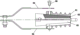
The strain clamp is used for fixing a wire to bear the tension of the wire and hanging the wire to a strain string or a hardware fitting on a pole tower. The prior wedge-shaped strain clamp is shown in fig. 7, and comprises a clamp body 61, an upper wedge core 62 and a lower wedge core 63 which are arranged in the clamp body 61, an upper hanging plate 64, a lower hanging plate 64 and a connecting bolt 65, wherein the following problems exist in the use process: 1, the upper hanging plate 64 and the lower hanging plate 64 of the traditional product are in direct contact with the thread positions of the connecting bolts 65, and the zinc layer is easily damaged under the rotation condition, so that the connecting part is easily damaged, and the service life is reduced; 2 when the traditional product is stressed by tightening a wire, the upper wedge core 62 and the lower wedge core 63 can scratch and scratch due to deformation at the wire inlet position of the wire clamp body 61, and the wire clamp body 61 is hung, so that the holding force is lowered; 3 the gripping force between the upper wedge core 62 and the lower wedge core 63 and the cable is small, so that the sliding accident is easy to occur, and the safety is low.
Disclosure of Invention
In order to solve the problems, the utility model aims to provide the grip-enhancement type wedge-shaped strain clamp with long service life.
The wedge-shaped strain clamp adopts the technical scheme that the wedge-shaped strain clamp comprises a clamp main body, an upper insulating core, a lower insulating core, an upper hanging plate and a lower hanging plate, wherein one end of the upper hanging plate and one end of the lower hanging plate are connected with the clamp main body through connecting bolts, the upper insulating core and the lower insulating core are respectively provided with an insulating core wire clamping groove for clamping a cable, the wedge-shaped strain clamp is characterized in that a clamp inserting opening for inserting the upper insulating core and the lower insulating core is arranged in the clamp main body, a wire inlet end of the clamp main body is provided with a bolt fixing part, a hanging plate positioning step is arranged on the bolt fixing part, hanging plate sleeving holes corresponding to the hanging plate positioning step are respectively arranged on the upper hanging plate and the lower hanging plate, a bolt mounting hole in butt joint with the connecting bolts is arranged in the hanging plate positioning step, and a clamp yielding groove is arranged at the inner wall of the bolt fixing part of the clamp inserting opening; the upper insulating core and the lower insulating core are respectively provided with an insulating core butt joint inclined plane matched with the wire clamp inserting opening of the wire clamp main body, and a contact step is arranged above the front part of the insulating core butt joint inclined plane.
The height of the contact step is 0.8-mm-1.2 mm.
A cable clamping opening is formed between the upper insulating core and the lower insulating core, and the cable clamping opening is of an oval structure.
An included angle a is formed between the upper surface and the lower surface of the upper insulating core and the lower surface of the lower insulating core, the degree of the included angle a is 5 degrees, an included angle b is formed between the upper surface and the lower surface of the wire clamp inserting opening, and the degree of the included angle b is 10 degrees.
The insulating core wire clamping groove is provided with wire clamping inverted teeth at equal intervals, and the height of the wire clamping inverted teeth is 1mm.
Insulating core material saving openings are arranged on the insulating core butt joint inclined plane at intervals.
The lower insulating core is provided with an anti-misplug clamping hook, and the upper insulating core is provided with an anti-misplug clamping opening corresponding to the anti-misplug clamping hook.
The upper and lower surfaces of the wire clip inserting opening adopt a grinding and polishing process.
The height of the contact step is 1mm.
The contact steps comprise a main contact step arranged transversely and at least two auxiliary contact steps arranged longitudinally.
The wedge-shaped strain clamp has the advantages that: the large outlet is adopted to design a deformation abdication structure, so that the insulating core is prevented from being scratched and hung on the wire clamp body, and the hanging plate positioning step is additionally arranged, so that the strength of the wire clamp body is directly improved, and the service life of a product is prolonged; and due to the design of the contact steps, the friction resistance of the stressed contact surface is reduced, and the holding force of the product is effectively improved.
Drawings
The utility model will be described in further detail with reference to the drawings and the detailed description.
FIG. 1 is a schematic view of the wedge strain clamp of the present utility model;
FIG. 2 is an exploded view of the clamp body, upper hanger plate and connecting bolt of the present utility model;
FIG. 3 is a cross-sectional view of an upper insulating core of the present utility model;
FIG. 4 is a top view of an upper insulating core of the present utility model;
FIG. 5 is a schematic illustration of the connection of an upper insulating core to a lower insulating core in accordance with the present utility model;
FIG. 6 is a left side view of an upper insulating core and a lower insulating core of the present utility model;
fig. 7 is a schematic structural view of a conventional wedge-shaped strain clamp.
Detailed Description
As shown in fig. 1-6, the wedge-shaped strain clamp comprises a clamp main body 1, an upper insulating core 2, a lower insulating core 3, an upper hanging plate 4 and a lower hanging plate 5, wherein one end of the upper hanging plate 4 and one end of the lower hanging plate 5 are connected with the clamp main body 1 through connecting bolts 6, the upper insulating core 2 and the lower insulating core 3 are respectively provided with an insulating core clamping groove 18 for clamping cables, a clamp inserting opening 10 for inserting the upper insulating core 2 and the lower insulating core 3 is arranged in the clamp main body 1, a bolt fixing part 11 is arranged at the wire inlet end of the clamp main body 1, a hanging plate positioning step 12 is arranged on the bolt fixing part 11, hanging plate sleeving holes 13 corresponding to the hanging plate positioning steps 12 are respectively arranged on the upper hanging plate 4 and the lower hanging plate 5, bolt mounting holes 14 which are in butt joint with the connecting bolts 6 are respectively arranged in the hanging plate positioning step 12, and a clamp inserting opening 16 is arranged at the inner wall of the bolt fixing part 11; the upper insulating core 2 with lower insulating core 3 all be equipped with the fastener main part 1 fastener inserted hole 10 matched with insulating core butt joint inclined plane 20, insulating core butt joint inclined plane 20 front portion top is equipped with contact step 21, add link plate location step, make the link plate of product and link plate location step direct atress (zinc is harder than aluminium, and link plate location step can strengthen hangers intensity, thereby directly increase body intensity), reduce the friction damage to link plate in with link plate location step position, thereby improve product life, the big outlet design of body warp the structure of stepping down, can improve the security of product (because insulating core is plastic nylon material, can appear because extrusion deformation when receiving the extrusion force, thereby lead to the big outlet of body to scratch and hang the insulating core, lead to the grip strength straight line decline, influence to the wire grip, thereby cause the incident).
The height of the contact step 21 is 0.8-mm-1.2 mm, the design of the contact step 21 can reduce the friction resistance of the stressed contact surface, and the grip strength is improved (by utilizing the principle, under the condition that the object is stressed in a sliding way, the smoother the sliding contact surface is, the smaller the sliding resistance is, the smaller the sliding contact surface is, the pressure intensity of the contact surface is increased, and the smaller the sliding resistance is).
The cable clamping opening 24 is formed between the upper insulating core 2 and the lower insulating core 3, the cable clamping opening 24 is of an oval structure, and when the wires are extruded by the holding force, the wires can be covered by the wire insulating layer to the greatest extent, so that the wires are completely contacted with the insulating core, and the holding force is enhanced.
An included angle a is formed between the upper surface and the lower surface of the upper insulating core 2 and the lower insulating core 3, the degree of the included angle a is 5 degrees, an included angle b is formed between the upper surface and the lower surface of the wire clamp inserting opening 10, the degree of the included angle b is 10 degrees, and the angle clamping effect is optimal.
The insulating core wire clamping grooves 18 are provided with wire clamping inverted teeth 19 at equal intervals, the height of the wire clamping inverted teeth 19 is 1mm, and when a wire is used as 1kV, the wire is not damaged after the wire is gripped by a product.
Insulating core material saving openings 22 are formed in the insulating core butt joint inclined plane 20 at intervals.
The lower insulating core 3 is provided with an erroneous insertion preventing clamping hook 25, the upper insulating core 2 is provided with an erroneous insertion preventing bayonet 26 corresponding to the erroneous insertion preventing clamping hook 25, and the phenomenon of misplacement of the insulating core can not occur when a wire is installed.
The upper and lower surfaces of the wire clip inserting opening 10 adopt a grinding and polishing process, so that the surfaces are cleaned, the sliding stress contact surface is smooth, and the friction resistance is reduced.
The height of the contact step 21 is 1mm.
The contact step 21 comprises a main contact step 29 arranged transversely and at least two auxiliary contact steps 28 arranged longitudinally, the contact forces being balanced.
The foregoing description of the preferred embodiments of the utility model is not intended to be limiting, but rather is intended to cover all modifications, equivalents, and alternatives falling within the spirit and principles of the utility model.
Claims (10)
1. The utility model provides a wedge strain clamp, includes fastener main part (1), goes up insulating core (2), down insulating core (3), goes up link plate (4), link plate (5) down, go up the one end of link plate (4) with the one end of link plate (5) down all pass through connecting bolt (6) with fastener main part (1) is connected, go up insulating core (2) with insulating core wire casing (18) that are used for the cable to press from both sides tightly down insulating core (3) all are equipped with, its characterized in that: the wire clamp comprises a wire clamp main body (1), wherein a wire clamp inserting opening (10) for inserting an upper insulating core (2) and a lower insulating core (3) is formed in the wire clamp main body (1), a bolt fixing part (11) is arranged at a wire inlet end of the wire clamp main body (1), a hanging plate positioning step (12) is arranged on the bolt fixing part (11), hanging plate sleeving holes (13) corresponding to the hanging plate positioning step (12) are formed in the upper hanging plate (4) and the lower hanging plate (5), a bolt installing hole (14) for being in butt joint with a connecting bolt (6) is formed in the hanging plate positioning step (12), and a wire clamp abdicating groove (16) is formed in the inner wall of the bolt fixing part (11) through the wire clamp inserting opening (10);
the upper insulating core (2) and the lower insulating core (3) are respectively provided with an insulating core butt-joint inclined surface (20) matched with the wire clamp inserting opening (10) of the wire clamp main body (1), and a contact step (21) is arranged above the front part of the insulating core butt-joint inclined surface (20).
2. The wedge strain clamp of claim 1, wherein: the height of the contact step (21) is 0.8-mm-1.2 mm.
3. The wedge strain clamp of claim 1, wherein: a cable clamping opening (24) is formed between the upper insulating core (2) and the lower insulating core (3), and the cable clamping opening (24) is of an oval structure.
4. The wedge strain clamp of claim 1, wherein: an included angle a is formed between the upper surface and the lower surface of the upper insulating core (2) and the lower surface of the lower insulating core (3), the degree of the included angle a is 5 degrees, an included angle b is formed between the upper surface and the lower surface of the wire clamp inserting opening (10), and the degree of the included angle b is 10 degrees.
5. The wedge strain clamp of claim 1, wherein: wire clamping inverted teeth (19) are arranged on the insulating core wire clamping grooves (18) at equal intervals, and the height of each wire clamping inverted tooth (19) is 1mm.
6. The wedge strain clamp of claim 1, wherein: insulating core material saving openings (22) are formed in the insulating core butt joint inclined plane (20) at intervals.
7. The wedge strain clamp of claim 1, wherein: the lower insulating core (3) is provided with an anti-misplug clamping hook (25), and the upper insulating core (2) is provided with an anti-misplug clamping opening (26) corresponding to the anti-misplug clamping hook (25).
8. The wedge strain clamp of claim 1, wherein: the upper and lower surfaces of the wire clip inserting opening (10) adopt a grinding and polishing process.
9. The wedge strain clamp of claim 1, wherein: the height of the contact step (21) is 1mm.
10. The wedge strain clamp of claim 1, wherein: the contact step (21) comprises a main contact step (29) arranged transversely and at least two auxiliary contact steps (28) arranged longitudinally.
Priority Applications (1)
| Application Number | Priority Date | Filing Date | Title |
|---|---|---|---|
| CN202320472170.4U CN219304435U (en) | 2023-03-14 | 2023-03-14 | Wedge-shaped strain clamp |
Applications Claiming Priority (1)
| Application Number | Priority Date | Filing Date | Title |
|---|---|---|---|
| CN202320472170.4U CN219304435U (en) | 2023-03-14 | 2023-03-14 | Wedge-shaped strain clamp |
Publications (1)
| Publication Number | Publication Date |
|---|---|
| CN219304435U true CN219304435U (en) | 2023-07-04 |
Family
ID=86952232
Family Applications (1)
| Application Number | Title | Priority Date | Filing Date |
|---|---|---|---|
| CN202320472170.4U Active CN219304435U (en) | 2023-03-14 | 2023-03-14 | Wedge-shaped strain clamp |
Country Status (1)
| Country | Link |
|---|---|
| CN (1) | CN219304435U (en) |
-
2023
- 2023-03-14 CN CN202320472170.4U patent/CN219304435U/en active Active
Similar Documents
| Publication | Publication Date | Title |
|---|---|---|
| JP3221316U (en) | Tension line clamp for carbon fiber composite core | |
| CN202930880U (en) | Carbon fiber composite core wire dedicated connection hardware | |
| CN219304435U (en) | Wedge-shaped strain clamp | |
| CN213271517U (en) | Splicing type quick-screwing YPN pneumatic pipe joint with self-clamping function | |
| CN201289991Y (en) | Vibration insulation hammer | |
| CN212137225U (en) | Single-wedge strain clamp for steel-cored aluminum strand | |
| CN217135119U (en) | Strain clamp for power transmission | |
| CN216215667U (en) | Exempt from trompil JDG spool connecting piece | |
| CN214707075U (en) | Wedge strain insulator spare fastener | |
| CN213367356U (en) | Fastening type strain clamp | |
| CN209358206U (en) | A kind of preformed carrying out safety backup wire clamp mounting structure of conducting wire pendency | |
| CN210985571U (en) | Parallel cluster type strain clamp | |
| CN209896583U (en) | Electric power construction fixing-line device | |
| CN106602492B (en) | Carbon fiber complex core optic fibre wire strain clamp | |
| CN112360928A (en) | Rotatable fixed connecting device of metal rope | |
| CN200987058Y (en) | Novel quick aluminium alloy strain clamp | |
| CN217507632U (en) | Mounting structure of omnidirectional ceiling antenna | |
| CN211830115U (en) | Bolt type strain clamp | |
| CN212477422U (en) | Suspension cable traction clamp for suspension cable overpass | |
| CN215990139U (en) | Bowl head type suspension clamp | |
| CN217010283U (en) | Self-locking C-shaped connecting wire clamp | |
| CN219592090U (en) | Four-core bundling strain clamp | |
| CN219281402U (en) | Wire drawing hardware fitting capable of preventing cable from loosening | |
| CN217362507U (en) | Four-core bunched wire strain clamp | |
| CN212231047U (en) | Strain clamp convenient to install |
Legal Events
| Date | Code | Title | Description |
|---|---|---|---|
| GR01 | Patent grant | ||
| GR01 | Patent grant |