CN219283376U - Self-cleaning flue gas waste heat recovery device - Google Patents
Self-cleaning flue gas waste heat recovery device Download PDFInfo
- Publication number
- CN219283376U CN219283376U CN202320776867.0U CN202320776867U CN219283376U CN 219283376 U CN219283376 U CN 219283376U CN 202320776867 U CN202320776867 U CN 202320776867U CN 219283376 U CN219283376 U CN 219283376U
- Authority
- CN
- China
- Prior art keywords
- box
- flue gas
- recovery
- air
- pipe
- Prior art date
- Legal status (The legal status is an assumption and is not a legal conclusion. Google has not performed a legal analysis and makes no representation as to the accuracy of the status listed.)
- Active
Links
Images


Classifications
-
- Y—GENERAL TAGGING OF NEW TECHNOLOGICAL DEVELOPMENTS; GENERAL TAGGING OF CROSS-SECTIONAL TECHNOLOGIES SPANNING OVER SEVERAL SECTIONS OF THE IPC; TECHNICAL SUBJECTS COVERED BY FORMER USPC CROSS-REFERENCE ART COLLECTIONS [XRACs] AND DIGESTS
- Y02—TECHNOLOGIES OR APPLICATIONS FOR MITIGATION OR ADAPTATION AGAINST CLIMATE CHANGE
- Y02E—REDUCTION OF GREENHOUSE GAS [GHG] EMISSIONS, RELATED TO ENERGY GENERATION, TRANSMISSION OR DISTRIBUTION
- Y02E20/00—Combustion technologies with mitigation potential
- Y02E20/30—Technologies for a more efficient combustion or heat usage
Abstract
The utility model discloses a smoke waste heat recovery device with a self-cleaning function, and particularly relates to the technical field of smoke waste heat utilization. The utility model can recycle the heat in the flue gas, is convenient for flushing the dust and smoke particles on the surface of the heat exchange tube, and can block the dust in the flue gas in the process of recycling the heat of the flue gas, thereby fundamentally avoiding the surface of the heat exchange tube from generating a large number of flue gas dust particles.
Description
Technical Field
The utility model relates to the technical field of flue gas waste heat utilization, in particular to a flue gas waste heat recovery device with a self-cleaning function.
Background
At present, a great amount of high temperature exists in flue gas exhausted by a boiler, and in order to avoid waste caused by direct discharge of the high temperature in the flue gas, the flue gas waste heat needs to be recovered and treated by a flue gas waste heat recovery device, and the heat carried by the flue gas is converted into available heat by a certain heat exchange mode, so that the effects of resource utilization and environmental protection are achieved.
The utility model patent of patent application number CN202121456923.X discloses a boiler flue gas waste heat recovery device, including flue gas preheating recoverer, air inlet fan and liquid pump, the both ends of flue gas preheating recoverer are provided with flue gas import and flue gas export respectively, inside air line and the circulating water pipeline of being provided with of flue gas preheating recoverer, air line and circulating water pipeline are crisscross distribution, and contactless, air line one end runs through behind the flue gas preheating recoverer and connects and be provided with the air inlet fan, and the other end runs through behind the flue gas preheating recoverer and connect and be provided with the gas delivery end, circulating water pipeline one end runs through behind the flue gas preheating recoverer and connects and be provided with the liquid pump, and the other end runs through behind the flue gas preheating recoverer and connect and be provided with the stop valve, the other end of stop valve is provided with temporary water storage jar through the pipe connection, flue gas preheating recoverer bottom is provided with the blow off pipe, and this structure can be efficient to recycle boiler flue gas waste heat, reaches energy-conserving purpose, the clean environment, more increases economic benefits.
However, when the structure is actually used, a large amount of flue gas dust and particles are also present in the flue gas discharged from the boiler, and when the flue gas is discharged into the recovery device, the surface of the inner pipeline is easy to adsorb a large amount of dust, so that pollution is caused.
Disclosure of Invention
The technical scheme of the utility model aims at the technical problem that the prior art is too single, provides a solution which is obviously different from the prior art, and aims at overcoming the defects of the prior art, and provides a self-cleaning smoke waste heat recovery device so as to solve the problems in the prior art.
In order to achieve the above purpose, the present utility model provides the following technical solutions: the utility model provides a self-cleaning's flue gas waste heat recovery device, includes the collection box, collection box one end is provided with the exhaust case, and its other end is provided with the inlet box, inlet box one end is provided with the air inlet, the exhaust case top is provided with the gas vent, collection box bottom is provided with the drain, the inside of collection box is provided with the heat exchange tube, the both ends of heat exchange tube all are provided with inlet tube and outlet pipe, the top of collection box is provided with the flushing structure;
the flushing structure comprises a sealing plate, the sealing plate is mounted on the back of the recovery box through bolts, the surface of the sealing plate is provided with an air pipe, the rear side of the air pipe is provided with a plurality of branch pipes, the surface of each branch pipe is provided with a plurality of air nozzles, the top of the recovery box is provided with a plurality of water diversion pipes, a plurality of communicating pipes are arranged between the water diversion pipes, one end of one water diversion pipe is provided with a connecting pipe, and the bottom of the water diversion pipe is provided with a plurality of nozzles.
Preferably, two ends of the recovery box are respectively communicated with the air inlet box and the exhaust box, the air inlet is communicated with the air inlet box, and the exhaust outlet is communicated with the exhaust box.
Preferably, the number of the heat exchange tubes is multiple, the heat exchange tubes are stacked in the recovery box in an S shape, and two ends of the heat exchange tubes are respectively communicated with the water inlet pipe and the water outlet pipe.
Preferably, the junction of inlet box and collection box is provided with the mounting panel, and the mounting panel passes through the bolt and can dismantle with the collection box and be connected, mounting panel and inlet box fixed connection.
Preferably, a first filter screen is arranged at the junction of the recovery box and the air inlet box, and a second filter screen is arranged in the air outlet.
Preferably, a plurality of branch pipes are communicated with the air pipe, the air tap is communicated with the branch pipes, and the air tap extends to the inside of the recovery box.
Preferably, one end of the connecting pipe is communicated with one of the water diversion pipes, the water diversion pipes are connected with each other through a communicating pipe, the nozzle is communicated with the water diversion pipes, and the nozzle extends to the inside of the recovery tank.
The utility model has the technical effects and advantages that:
through setting up the flushing structure, make the air current enter into the inside of a plurality of branch pipes through the air pipe after the air pipe is connected with the blowing equipment, last through a plurality of air nozzles blowout, can wash away the dust that the heat exchange tube surface adheres to, after connecting pipe one end put through water supply equipment simultaneously, make rivers enter into the inside of one of them shunt tubes, utilize the mutual communication effect of communicating pipe, make rivers flow through a plurality of shunt tubes, last through the nozzle blowout, utilize the blowing of air current and the washing of rivers, can reach clean effect to the surface of heat exchange tube;
through entering into the inside back of collection box with the flue gas through the inlet box, can block the dust granule in the flue gas through first filter screen, fundamentally avoids a large amount of dust granule to adsorb at the inside heat exchange tube surface of collection box, and when the flue gas after waste heat recovery passes through the gas vent exhaust moreover, utilizes its inside second filter screen, can filter the dust in the flue gas once more when the flue gas is discharged, reduces the dust granule in the flue gas and causes the influence to the environment.
Drawings
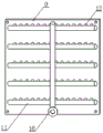
Fig. 1 is a schematic diagram of the overall structure of the present utility model.
Fig. 2 is a schematic diagram of the structure of the recovery tank and the air inlet tank when the recovery tank is separated.
Fig. 3 is a schematic view of the surface structure of the sealing plate according to the present utility model.
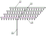
FIG. 4 is a schematic view of a plurality of shunt tubes according to the present utility model.
The reference numerals are: 1. a recovery box; 2. an exhaust box; 3. an air inlet box; 4. an air inlet; 5. an exhaust port; 6. a heat exchange tube; 7. a water inlet pipe; 8. a water outlet pipe; 9. a sealing plate; 10. an air pipe; 11. a branch pipe; 12. an air tap; 13. a water diversion pipe; 14. a communicating pipe; 15. a connecting pipe; 16. a nozzle; 17. a mounting plate; 18. a first filter screen; 19. and a second filter screen.
Description of the embodiments
The following description of the embodiments of the present utility model will be made clearly and completely with reference to the accompanying drawings, in which it is apparent that the embodiments described are only some embodiments of the present utility model, but not all embodiments. All other embodiments, which can be made by those skilled in the art based on the embodiments of the utility model without making any inventive effort, are intended to be within the scope of the utility model.
The flue gas waste heat recovery device with the self-cleaning function as shown in the attached drawings 1-4 comprises a recovery box 1, wherein one end of the recovery box 1 is provided with an exhaust box 2, the other end of the recovery box is provided with an air inlet box 3, one end of the air inlet box 3 is provided with an air inlet 4, the top of the exhaust box 2 is provided with an air outlet 5, the bottom of the recovery box 1 is provided with a sewage outlet, the inside of the recovery box 1 is provided with a heat exchange tube 6, both ends of the heat exchange tube 6 are provided with a water inlet pipe 7 and a water outlet pipe 8, and the top of the recovery box 1 is provided with a flushing structure;
the flushing structure comprises a sealing plate 9, the sealing plate 9 is mounted on the back of the recovery box 1 through bolts, an air pipe 10 is arranged on the surface of the sealing plate 9, a plurality of branch pipes 11 are arranged on the rear side of the air pipe 10, a plurality of air nozzles 12 are arranged on the surface of each of the plurality of branch pipes 11, a plurality of water diversion pipes 13 are arranged at the top of the recovery box 1, a communicating pipe 14 is arranged between the plurality of water diversion pipes 13, a connecting pipe 15 is arranged at one end of one water diversion pipe 13, and a plurality of nozzles 16 are arranged at the bottom of the water diversion pipe 13.
When the structure is specifically used, in the process of recovering the heat of the flue gas, the flue gas enters the air inlet box 3 from the air inlet 4 and enters the recovery box 1 through the air inlet box 3, at the moment, one end of the water inlet pipe 7 is filled with water, so that the water enters the plurality of S-shaped heat exchange pipes 6 and finally is discharged through the water outlet pipe 8, and when the water flows in the S-shaped heat exchange pipes 6, the heat in the flue gas can be taken away, and the water in the heat exchange pipes 6 is heated, so that the heat recovery effect is achieved;
after the heat is recovered by the recovery box 1, the heat enters the exhaust box 2 and is finally exhausted through the exhaust port 5, so that the effects of recovering and exhausting the heat of the flue gas are achieved;
when the heat of the flue gas is recovered through the heat exchange tube 6 in the recovery box 1, a large amount of flue gas particles and dust are adsorbed on the outer surface of the heat exchange tube 6, the air tube 10 is connected with the air blowing device, so that the air flow enters the inside of the plurality of branch tubes 11 through the air tube 10 and finally is sprayed out through the plurality of air nozzles 12, the dust attached to the outer surface of the heat exchange tube 6 can be washed out, one end of the connecting tube 15 is communicated with the water supply device, so that the water flow enters the inside of one of the water diversion tubes 13, the water flow is promoted to flow through the plurality of water diversion tubes 13 by utilizing the mutual communication effect of the communicating tube 14, and finally the sprayed water is sprayed out through the nozzle 16, so that the sprayed water directly washes the surface of the heat exchange tube 6 from the lower part, the clean effect of the heat exchange tube 6 can be achieved, and the clean sewage is discharged through the drain 6 at the bottom of the recovery box 1;
the staff can dismantle shrouding 9 through the bolt, conveniently maintains the operation to the inside heat exchange tube 6 of recovery tank 1.
In a preferred embodiment, as shown in fig. 1 and 2, two ends of the recovery box 1 are respectively communicated with the air inlet box 3 and the exhaust box 2, the air inlet 4 is communicated with the air inlet box 3, the exhaust port 5 is communicated with the exhaust box 2, so that high-temperature smoke can enter the air inlet box 3 through the air inlet 4 and enter the recovery box 1 through the air inlet box 3, after heat recovery of the recovery box 1, the high-temperature smoke enters the exhaust box 2, and finally is discharged through the exhaust port 5, thereby achieving the effects of recovering and discharging the heat of the smoke.
In a preferred embodiment, as shown in fig. 1 and 2, the number of the heat exchange tubes 6 is multiple, the heat exchange tubes 6 are stacked in an S shape in the recovery tank 1, two ends of the heat exchange tubes 6 are respectively communicated with the water inlet tube 7 and the water outlet tube 8, so that when the heat of the flue gas is recovered, one end of the water inlet tube 7 is introduced with water, the water enters the heat exchange tubes 6 in an S shape, and finally, the water is discharged through the water outlet tube 8, when the water flows in the heat exchange tubes 6 in an S shape, the heat in the flue gas can be taken away, and the water in the heat exchange tubes 6 is subjected to heat treatment, so that the heat recovery effect is achieved.
In a preferred embodiment, as shown in fig. 2, a mounting plate 17 is arranged at the connection part of the air inlet box 3 and the recovery box 1, and the mounting plate 17 is detachably connected with the recovery box 1 through bolts, the mounting plate 17 is fixedly connected with the air inlet box 3, so that after the mounting plate 17 at one end of the air inlet box 3 is in butt joint with one end of the recovery box 1, the mounting plate 17 can be connected with the recovery box 1 through bolts, the air inlet box 3 is connected with the recovery box 1, and the disassembly treatment between the air inlet box 3 and the recovery box 1 is facilitated.
In a preferred embodiment, as shown in fig. 2, a first filter screen 18 is disposed at the junction of the recovery tank 1 and the air inlet tank 3, and a second filter screen 19 is disposed in the air outlet 5, so that when the flue gas enters the recovery tank 1 through the air inlet tank 3, dust particles in the flue gas can be blocked by the first filter screen 18, a large amount of dust particles are prevented from being adsorbed on the surface of the heat exchange tube 6 in the recovery tank 1, and the second filter screen 19 in the air outlet 5 can filter the dust in the flue gas again when the flue gas is exhausted, so that the influence of the dust particles in the flue gas on the environment is reduced.
In a preferred embodiment, as shown in fig. 3, the plurality of branch pipes 11 are all communicated with the air pipe 10, the air tap 12 is communicated with the branch pipes 11, and the air tap 12 extends to the inside of the recovery tank 1, so that the air pipe 10 is connected with the air blowing device, air flow enters the inside of the plurality of branch pipes 11 through the air pipe 10, and finally is sprayed out through the plurality of air taps 12, so that dust attached to the outer surface of the heat exchange pipe 6 can be washed, and further the dust on the surface of the heat exchange pipe 6 can be cleaned conveniently.
In a preferred embodiment, as shown in fig. 1, 2 and 4, one end of the connecting pipe 15 is communicated with one of the water diversion pipes 13, the plurality of water diversion pipes 13 are connected with each other through the communicating pipe 14, the nozzle 16 is communicated with the water diversion pipe 13, and the nozzle 16 extends to the inside of the recovery tank 1, so that one end of the connecting pipe 15 is conveniently connected with the water supply equipment, water flows into the inside of one of the water diversion pipes 13, the water flows through the plurality of water diversion pipes 13 by utilizing the mutual communication effect of the communicating pipe 14, and finally is sprayed out through the nozzle 16, so that the sprayed water directly washes the surface of the heat exchange pipe 6 from the height to the lower position, and the cleaning effect of the heat exchange pipe 6 can be improved.
When the structure is specifically used, after the flue gas enters the recovery box 1 through the air inlet box 3, dust particles in the flue gas can be blocked through the first filter screen 18, so that a large amount of dust particles are prevented from being adsorbed on the surface of the heat exchange tube 6 in the recovery box 1, and the second filter screen 19 in the exhaust port 5 can be used for filtering dust in the flue gas again when the flue gas is exhausted, so that the influence of the dust particles in the flue gas on the environment is reduced;
meanwhile, after the mounting plate 17 and the recovery box 1 are connected through bolts, the disassembly treatment between the air inlet box 3 and the recovery box 1 is facilitated for workers, and the surface of the first filter screen 18 is further facilitated to be cleaned.
The foregoing description of the preferred embodiments of the utility model is not intended to limit the utility model to the precise form disclosed, and any such modifications, equivalents, and alternatives falling within the spirit and principles of the utility model are intended to be included within the scope of the utility model.
Claims (7)
1. The utility model provides a self-cleaning's flue gas waste heat recovery device, includes collection box (1), its characterized in that: the recovery tank is characterized in that one end of the recovery tank (1) is provided with an exhaust tank (2), the other end of the recovery tank is provided with an air inlet tank (3), one end of the air inlet tank (3) is provided with an air inlet (4), the top of the exhaust tank (2) is provided with an air outlet (5), the bottom of the recovery tank (1) is provided with a sewage outlet, the inside of the recovery tank (1) is provided with a heat exchange tube (6), both ends of the heat exchange tube (6) are provided with a water inlet tube (7) and a water outlet tube (8), and the top of the recovery tank (1) is provided with a flushing structure;
the flushing structure comprises a sealing plate (9), the sealing plate (9) is mounted on the back of the recovery box (1) through bolts, an air pipe (10) is arranged on the surface of the sealing plate (9), a plurality of branch pipes (11) are arranged on the rear side of the air pipe (10), a plurality of air nozzles (12) are arranged on the surface of each branch pipe (11), a plurality of water diversion pipes (13) are arranged at the top of the recovery box (1), communicating pipes (14) are arranged between the water diversion pipes (13), a connecting pipe (15) is arranged at one end of one water diversion pipe (13), and a plurality of nozzles (16) are arranged at the bottom of the water diversion pipe (13).
2. The self-cleaning flue gas waste heat recovery device according to claim 1, wherein: the two ends of the recovery box (1) are respectively communicated with the air inlet box (3) and the exhaust box (2), the air inlet (4) is communicated with the air inlet box (3), and the exhaust port (5) is communicated with the exhaust box (2).
3. The self-cleaning flue gas waste heat recovery device according to claim 1, wherein: the number of the heat exchange tubes (6) is multiple, the heat exchange tubes (6) are stacked in the recovery box (1) in an S shape, and two ends of the heat exchange tubes (6) are respectively communicated with the water inlet tube (7) and the water outlet tube (8).
4. The self-cleaning flue gas waste heat recovery device according to claim 1, wherein: the utility model discloses a gas inlet box, including gas inlet box (3), recovery box (1), mounting panel (17) are provided with the junction of gas inlet box (3) and recovery box (1), and mounting panel (17) are connected with recovery box (1) can be dismantled through the bolt, mounting panel (17) and gas inlet box (3) fixed connection.
5. The self-cleaning flue gas waste heat recovery device according to claim 1, wherein: the recycling bin (1) is provided with a first filter screen (18) at the junction of the recycling bin and the air inlet bin (3), and a second filter screen (19) is arranged in the air outlet (5).
6. The self-cleaning flue gas waste heat recovery device according to claim 1, wherein: the plurality of branch pipes (11) are communicated with the air pipe (10), the air tap (12) is communicated with the branch pipes (11), and the air tap (12) extends to the inside of the recovery box (1).
7. The self-cleaning flue gas waste heat recovery device according to claim 1, wherein: one end of the connecting pipe (15) is communicated with one of the water diversion pipes (13), the water diversion pipes (13) are connected with each other through the communicating pipe (14), the nozzle (16) is communicated with the water diversion pipe (13), and the nozzle (16) extends to the inside of the recovery box (1).
Priority Applications (1)
| Application Number | Priority Date | Filing Date | Title |
|---|---|---|---|
| CN202320776867.0U CN219283376U (en) | 2023-04-11 | 2023-04-11 | Self-cleaning flue gas waste heat recovery device |
Applications Claiming Priority (1)
| Application Number | Priority Date | Filing Date | Title |
|---|---|---|---|
| CN202320776867.0U CN219283376U (en) | 2023-04-11 | 2023-04-11 | Self-cleaning flue gas waste heat recovery device |
Publications (1)
| Publication Number | Publication Date |
|---|---|
| CN219283376U true CN219283376U (en) | 2023-06-30 |
Family
ID=86919595
Family Applications (1)
| Application Number | Title | Priority Date | Filing Date |
|---|---|---|---|
| CN202320776867.0U Active CN219283376U (en) | 2023-04-11 | 2023-04-11 | Self-cleaning flue gas waste heat recovery device |
Country Status (1)
| Country | Link |
|---|---|
| CN (1) | CN219283376U (en) |
-
2023
- 2023-04-11 CN CN202320776867.0U patent/CN219283376U/en active Active
Similar Documents
| Publication | Publication Date | Title |
|---|---|---|
| CN203802422U (en) | Water-gas heat-exchange heat-recovery device for ultrasonic dish-washing machine | |
| CN209763126U (en) | dust removal boiler with heat recovery function | |
| CN219283376U (en) | Self-cleaning flue gas waste heat recovery device | |
| CN207237577U (en) | A kind of flue gas processing device of high-efficiency environment friendly | |
| CN106000056A (en) | Yellow phosphorus tail gas purification method and system | |
| CN206867983U (en) | A kind of chimney exhaust gas processing device | |
| CN201901653U (en) | Pipeline washing device of a dry-process acetylene generator | |
| CN107081050A (en) | A kind of chimney exhaust gas processing device | |
| CN209558392U (en) | A kind of high-temperature flue gas cooling device for preventing dioxin from synthesizing again | |
| CN113405384A (en) | Heat exchange unit, flue gas waste heat recovery exchanger and process | |
| CN206073047U (en) | Energy saving and environment friendly normal-pressure boiler system | |
| CN216878505U (en) | Wet dedusting absorption tower | |
| CN206621928U (en) | Efficient energy-saving water-saving spray system applied to the new OG systems of once dust collection of converter | |
| CN205897905U (en) | Modular residual heat from flue gas device | |
| CN211316991U (en) | High-efficient device that utilizes of kiln flue gas | |
| CN206361675U (en) | A kind of water capacity formula economizer | |
| CN206399222U (en) | A kind of heat recovery system for organic particulate matter air draft | |
| CN204987810U (en) | Heat pump is dust purification device for drying system | |
| CN215832528U (en) | Heat exchange unit and flue gas waste heat recovery exchanger | |
| CN211575156U (en) | Boiler steam soot blower | |
| CN210153842U (en) | Power station boiler flue gas waste heat utilization equipment | |
| CN103523837B (en) | Waste heat recovery and smell removal treatment system for phenolic water | |
| CN213375727U (en) | A spray dust remover for environmental engineering | |
| CN203513308U (en) | Phenolic water waste heat recovery and smell removal treatment system | |
| CN212843099U (en) | Waste gas heat exchange cooling system |
Legal Events
| Date | Code | Title | Description |
|---|---|---|---|
| GR01 | Patent grant | ||
| GR01 | Patent grant |