CN219283143U - Adjustable floor lamp - Google Patents
Adjustable floor lamp Download PDFInfo
- Publication number
- CN219283143U CN219283143U CN202320685702.2U CN202320685702U CN219283143U CN 219283143 U CN219283143 U CN 219283143U CN 202320685702 U CN202320685702 U CN 202320685702U CN 219283143 U CN219283143 U CN 219283143U
- Authority
- CN
- China
- Prior art keywords
- lamp
- floor lamp
- switch
- seat
- horse race
- Prior art date
- Legal status (The legal status is an assumption and is not a legal conclusion. Google has not performed a legal analysis and makes no representation as to the accuracy of the status listed.)
- Active
Links
Images
Landscapes
- Fastening Of Light Sources Or Lamp Holders (AREA)
- Non-Portable Lighting Devices Or Systems Thereof (AREA)
Abstract
The utility model belongs to the technical field of floor lamp structures, and particularly relates to an adjustable floor lamp, which comprises a base and support rods vertically connected to the top of the base, wherein a lamp box is rotationally connected to the top end of the support rods, LED horse race lamp belts are connected to the periphery of the inner wall of the lamp box, light-transmitting plates are connected to the inner wall of the lamp box and one side, close to the LED horse race lamp belts, of the lamp box, guide rods are symmetrically connected to the two sides of the lamp box through support rods, movable seats are tightly sleeved on the outer sides of the two guide rods in a sliding manner, clamping grooves are formed in one ends, far away from the guide rods, of the movable seats, and connecting blocks are connected to the inner sides of the clamping grooves in a fitting manner; through setting up the cooperation of rotatory lamp house and adjustable height and angle's floor lamp main part, can adjust the scope of illumination, have fashion unique structural style, have the effect of good intention decoration, can produce the spiral of constantly changing and dazzle colored lamp light, have beautiful light effect, have very much the sight.
Description
Technical Field
The utility model belongs to the technical field of floor lamp structures, and particularly relates to an adjustable floor lamp.
Background
The floor lamp is a household common lighting lamp, is commonly placed in a bedroom or a study and is used in a wall-leaning area, the floor lamp is commonly used for local illumination, most of the existing floor lamps are composed of a support, a bulb and a lampshade, light uniformly irradiates from the periphery and the top surface of the lampshade, the top surface of the lampshade is closed, the light uniformly irradiates from the periphery, an adjustable floor lamp is disclosed in patent with publication number CN209511682U, the height of the floor lamp can be adjusted, an LED floor lamp with an adjustable light angle is disclosed in patent with publication number CN218327656U, the height of the floor lamp and the angle on a vertical surface can be adjusted, in the prior art, the floor lamp is not flexible enough to adjust the illumination range, the structure is common, the effect of creative decoration is poor, and the attractiveness is low.
For this purpose, an adjustable floor lamp is designed to solve the above-mentioned problems.
Disclosure of Invention
To solve the problems set forth in the background art. The utility model provides an adjustable floor lamp, which can adjust the illumination range by arranging the rotary lamp box and the floor lamp main body with adjustable height and angle, has fashionable and unique structural modeling, has good creative decorative effect, can generate continuously-changed spiral colorful lamp light, has beautiful lighting effect and has great ornamental value.
In order to achieve the above purpose, the present utility model provides the following technical solutions: the utility model provides an adjustable floor lamp, is in including base and perpendicular connection the bracing piece at base top, the top rotation of bracing piece is connected with the lamp house, be connected with LED ticker tape around the inner wall of lamp house, the inner wall of lamp house just is close to one side in LED ticker tape and is connected with the light-passing board, the both sides of lamp house are connected with the guide bar through branch symmetry, two the equal closely sliding in outside of guide bar has cup jointed the removal seat, the centre gripping groove has been seted up to the one end that the guide bar was kept away from to the removal seat, the inboard laminating of centre gripping groove is connected with the connecting block, the one end that the removal seat was kept away from to the connecting block is connected with the floor lamp main part, it has the bolt shaft to remove the one end through connection that the seat side just is located the centre gripping groove, the connecting block rotates the outside of cup jointing at the bolt shaft, the screw end spiro union of bolt shaft has fastening nut, just fastening nut compresses tightly the side at the removal seat.
Preferably, the support rod is in a tubular shape, a first switch, a second switch and a third switch are sequentially arranged on the outer side of the top of the support rod from top to bottom, a wire is arranged on the inner side of the support rod, the first switch is connected with the LED ticker strip through the wire, and the second switch and the third switch are connected with the two floor lamp bodies through the wires respectively.
Preferably, the lamp box is of a rectangular frame structure, a dimming controller is arranged on one side of the bottom of the lamp box, and the dimming controller is connected with the LED ticker tape through a wire.
Preferably, the bottom center of the lamp box is connected with a support sleeve, and the top end of the support rod is sleeved on the inner side of the support sleeve in an interference manner through a bearing.
Preferably, a through hole is formed in one end of the movable seat, a damping ring is fixedly connected to the inner side of the through hole, and the movable seat is positioned at the through hole and is in friction sleeving connection with the outer side of the guide rod through the damping ring.
Compared with the prior art, the utility model has the beneficial effects that:
1. the rotatable lamp box, the LED horse race lamp belt and the light-transmitting plate are matched, so that continuously-changing spiral colorful lamp light can be generated, a beautiful light effect is achieved, and the ornamental value is achieved;
2. through setting up on the guide bar and can downwardly moving and pivoted remove the seat to and remove seat one end setting can rotate and fixed floor lamp main part, can adjust the height and the illumination angle of floor lamp main part in vertical direction, cooperate with the lamp house that can rotate simultaneously, can adjust illumination's scope in the horizontal direction, combine both sides to adjust floor lamp main part, can put out different unique molding, have the effect of good intention decoration.
Drawings
The accompanying drawings are included to provide a further understanding of the utility model and are incorporated in and constitute a part of this specification, illustrate the utility model and together with the embodiments of the utility model, serve to explain the utility model. In the drawings:
FIG. 1 is a schematic diagram of the overall structure of the present utility model;
FIG. 2 is a schematic diagram of a lamp box according to the present utility model;
FIG. 3 is a schematic view of the position of the floor lamp body of the present utility model on a guide bar;
FIG. 4 is a schematic diagram of the connection structure of the lamp box and the support rod of the present utility model;
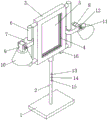
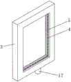
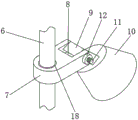
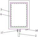
reference numerals in the drawings: 1. a base; 2. a support rod; 3. a light box; 4. LED horse race lamp belt; 5. a light-transmitting plate; 6. a guide rod; 7. a movable seat; 8. a clamping groove; 9. a connecting block; 10. a floor lamp body; 11. a bolt shaft; 12. a fastening nut; 13. a first switch; 14. a second switch; 15. a third switch; 16. a dimming controller; 17. a support sleeve; 18. a damping ring.
Detailed Description
The following description of the embodiments of the present utility model will be made clearly and completely with reference to the accompanying drawings, in which it is apparent that the embodiments described are only some embodiments of the present utility model, but not all embodiments. All other embodiments, which can be made by those skilled in the art based on the embodiments of the utility model without making any inventive effort, are intended to be within the scope of the utility model.
As shown in fig. 1-4;
the utility model provides an adjustable floor lamp, including base 1 and perpendicular bracing piece 2 of connecting at the 1 top of base, the top rotation of bracing piece 2 is connected with lamp house 3, the inner wall of lamp house 3 is connected with LED horse race lamp area 4 all around, the inner wall of lamp house 3 just is close to one side of LED horse race lamp area 4 and is connected with light-passing board 5, the both sides of lamp house 3 are connected with guide bar 6 through branch symmetry, the outside of two guide bars 6 has all closely slipped and has cup jointed and has moved seat 7, the clamping groove 8 has been seted up to the one end that moves seat 7 kept away from guide bar 6, the inboard laminating of clamping groove 8 is connected with connecting block 9, the one end that moves seat 7 was kept away from of connecting block 9 is connected with floor lamp main part 10, move seat 7 side and be located clamping groove 8 one end through connection have bolt shaft 11, connecting block 9 rotates the outside of cup jointing at bolt shaft 11, the screw end spiro union of bolt shaft 11 has fastening nut 12, and fastening nut 12 compresses tightly the side at moving seat 7, the one end that moves seat 7 and has elasticity, fastening nut 12 adopts butterfly nut 12, make convenient rotation fastening nut 12 for connecting block 9 presss from both sides tightly and fixes in clamping groove 8.
It should be noted that: as shown in fig. 1, the supporting rod 2 is in a tubular shape, the first switch 13, the second switch 14 and the third switch 15 are sequentially installed on the outer side of the top of the supporting rod 2 from top to bottom, wires are arranged on the inner side of the supporting rod 2, wiring is facilitated, the first switch 13 is connected with the LED ticker strip 4 through the wires, the second switch 14 and the third switch 15 are respectively connected with the two floor lamp bodies 10 through the wires, and the switches of the LED ticker strip 4 and the two floor lamp bodies 10 can be respectively and independently controlled.
In this embodiment: when the LED horse race lamp strip is used, through setting up the movable seat 7 that can move downwards and rotate on the guide bar 6, and set up the floor lamp main part 10 that can rotate and fix at movable seat 7 one end, can adjust the height and the illumination angle of floor lamp main part 10 in vertical direction, cooperate with rotatable lamp house 3 simultaneously, can adjust the illumination's scope in the horizontal direction, effectively increased the illumination scope of current floor lamp, combine both sides to adjust floor lamp main part 10, can put out different unique molding, in actual use, because the light of LED horse race lamp strip 4 is like rivers removes around light-transmitting plate 5, make the light-transmitting plate 5 shine colored light, can attach the photograph or write on light-transmitting plate 5, can demonstrate fashion unique house culture, have the effect of good intention decoration, through setting up lamp house 3 that can rotate, LED horse race lamp strip 4 and the cooperation of light-transmitting plate 5, can produce the spiral that constantly changes dazzle the color lamp, have beautiful light effect, the ornamental effect has.
In a preferred embodiment, as shown in fig. 1, 2 and 4, the lamp box 3 is configured as a rectangular frame, one side of the bottom of the lamp box 3 is provided with a dimming controller 16, and the dimming controller 16 is connected with the LED ticker tape 4 through a wire, for controlling and adjusting the light effect displayed by the LED ticker tape 4.
In a preferred embodiment, as shown in fig. 1 and 4, the bottom center of the lamp box 3 is connected with a supporting sleeve 17, the top end of the supporting rod 2 is sleeved on the inner side of the supporting sleeve 17 in an interference manner through a bearing, so that the lamp box 3 can freely rotate on the supporting rod 2, and in practical application, the lamp box 3 can be rotated by hands, and the lamp box is convenient to use.
In a preferred embodiment, as shown in fig. 1 and 3, a through hole is formed at one end of the movable seat 7, a damping ring 18 is fixedly connected to the inner side of the through hole, the movable seat 7 is located at the through hole and is in friction fit connection with the outer side of the guide rod 6 through the damping ring 18, the damping ring 18 can be made of nylon, wear-resistant and flexible, has high compressive strength, and can be used for moving and rotating the movable seat 7 along the guide rod 6 by force when the movable seat 7 is used, the movable seat 7 is fixed on the guide rod 6 after the movable seat 7 is loosened, and the position of the movable seat 7 can be flexibly adjusted, so that the position of the floor lamp main body 10 can be flexibly adjusted, and the movable seat is convenient to use.
Finally, it should be noted that: the foregoing description is only a preferred embodiment of the present utility model, and the present utility model is not limited thereto, but it is to be understood that modifications and equivalents of some of the technical features described in the foregoing embodiments may be made by those skilled in the art, although the present utility model has been described in detail with reference to the foregoing embodiments. Any modification, equivalent replacement, improvement, etc. made within the spirit and principle of the present utility model should be included in the protection scope of the present utility model.
Claims (5)
1. The utility model provides an adjustable floor lamp, is in including base (1) and perpendicular bracing piece (2) of connecting base (1) top, its characterized in that: the top of bracing piece (2) rotates and is connected with lamp house (3), be connected with LED horse race lamp area (4) around the inner wall of lamp house (3), the inner wall of lamp house (3) and be close to one side of LED horse race lamp area (4) are connected with light-passing board (5), the both sides of lamp house (3) are connected with guide bar (6) through branch symmetry, two the outside of guide bar (6) is all closely slided and is cup jointed and remove seat (7), the one end that guide bar (6) was kept away from to remove seat (7) has been seted up centre gripping groove (8), the inside laminating of centre gripping groove (8) is connected with connecting block (9), the one end of keeping away from of connecting block (9) removes seat (7) is connected with floor lamp main part (10), remove seat (7) side and be located the one end through connection of centre gripping groove (8) have bolt shaft (11), connecting block (9) rotate and cup joint in the outside of bolt shaft (11), the screw thread end spiro union of bolt shaft (11) has fastening nut (12), just fastening nut (12) compress tightly in the side of removing seat (7).
2. The adjustable floor lamp of claim 1, wherein: the supporting rod (2) is arranged into a tube shape, a first switch (13), a second switch (14) and a third switch (15) are sequentially arranged on the outer side of the top of the supporting rod (2) from top to bottom, a wire is arranged on the inner side of the supporting rod (2), the first switch (13) is connected with the LED horse race lamp strip (4) through the wire, and the second switch (14) and the third switch (15) are respectively connected with the two floor lamp bodies (10) through the wire.
3. An adjustable floor lamp as defined in claim 2, wherein: the lamp box (3) is of a rectangular frame structure, a dimming controller (16) is arranged on one side of the bottom of the lamp box (3), and the dimming controller (16) is connected with the LED horse race lamp strip (4) through a wire.
4. An adjustable floor lamp as defined in claim 3, wherein: the bottom center of the lamp box (3) is connected with a support sleeve (17), and the top end of the support rod (2) is sleeved on the inner side of the support sleeve (17) in an interference mode through a bearing.
5. The adjustable floor lamp of claim 1, wherein: the through hole is formed in one end of the movable seat (7), the damping ring (18) is fixedly connected to the inner side of the through hole, and the movable seat (7) is located at the through hole and is in friction sleeve joint with the outer side of the guide rod (6) through the damping ring (18).
Priority Applications (1)
| Application Number | Priority Date | Filing Date | Title |
|---|---|---|---|
| CN202320685702.2U CN219283143U (en) | 2023-03-31 | 2023-03-31 | Adjustable floor lamp |
Applications Claiming Priority (1)
| Application Number | Priority Date | Filing Date | Title |
|---|---|---|---|
| CN202320685702.2U CN219283143U (en) | 2023-03-31 | 2023-03-31 | Adjustable floor lamp |
Publications (1)
| Publication Number | Publication Date |
|---|---|
| CN219283143U true CN219283143U (en) | 2023-06-30 |
Family
ID=86919222
Family Applications (1)
| Application Number | Title | Priority Date | Filing Date |
|---|---|---|---|
| CN202320685702.2U Active CN219283143U (en) | 2023-03-31 | 2023-03-31 | Adjustable floor lamp |
Country Status (1)
| Country | Link |
|---|---|
| CN (1) | CN219283143U (en) |
-
2023
- 2023-03-31 CN CN202320685702.2U patent/CN219283143U/en active Active
Similar Documents
| Publication | Publication Date | Title |
|---|---|---|
| CN210398667U (en) | Landscape lamp convenient to rotation regulation | |
| CN219283143U (en) | Adjustable floor lamp | |
| CN211475648U (en) | Hidden intelligent lighting lamp | |
| CN213019429U (en) | Illumination range adjustable illumination color lamp | |
| CN109595489A (en) | A kind of adjustable household floor lamp | |
| CN208687560U (en) | A kind of Landscape Lamp being adjusted by rotation | |
| CN204901472U (en) | Puppet desk lamp warp | |
| CN111664408A (en) | Adjustable solar LED landscape lamp | |
| CN207674156U (en) | A kind of adjustable lamps and lanterns of lampshade | |
| CN216821943U (en) | Landscape tree structure with colored lamps | |
| CN208817173U (en) | A kind of light luxurious floor lamp structure of intelligence | |
| CN212156908U (en) | Outdoor LED (light-emitting diode) landscape lamp | |
| CN204879528U (en) | Lamps and lanterns with hidden lamp shade of polychrome | |
| CN220119279U (en) | High-light-efficiency crystal spotlight capable of adjusting color temperature | |
| CN213019370U (en) | Embedded spotlight capable of rotating at multiple angles | |
| CN208381962U (en) | A kind of artistic lamp | |
| CN209431169U (en) | A kind of indoor design landing illuminating lamp | |
| CN211502604U (en) | High ground lamp for garden | |
| CN214369502U (en) | Intelligent three-dimensional modeling lamp | |
| CN209540627U (en) | A kind of resin decorative lamp for garden | |
| CN208579261U (en) | A kind of outdoor use Waterproof LED lighting device | |
| CN215570093U (en) | Shot-light convenient to installation | |
| CN212361844U (en) | Palace lantern molding landscape lamp | |
| CN216492222U (en) | A suspension type flower case that what was used for in scenery garden had illumination function concurrently | |
| CN215275761U (en) | Toy DIY desktop lamp house |
Legal Events
| Date | Code | Title | Description |
|---|---|---|---|
| GR01 | Patent grant | ||
| GR01 | Patent grant |