CN219275549U - Clamp mechanism of bearing ring superfine grinding machine - Google Patents
Clamp mechanism of bearing ring superfine grinding machine Download PDFInfo
- Publication number
- CN219275549U CN219275549U CN202320164279.1U CN202320164279U CN219275549U CN 219275549 U CN219275549 U CN 219275549U CN 202320164279 U CN202320164279 U CN 202320164279U CN 219275549 U CN219275549 U CN 219275549U
- Authority
- CN
- China
- Prior art keywords
- clamping
- sliding
- rollers
- bearing ring
- clamping rollers
- Prior art date
- Legal status (The legal status is an assumption and is not a legal conclusion. Google has not performed a legal analysis and makes no representation as to the accuracy of the status listed.)
- Active
Links
Images
Classifications
-
- Y—GENERAL TAGGING OF NEW TECHNOLOGICAL DEVELOPMENTS; GENERAL TAGGING OF CROSS-SECTIONAL TECHNOLOGIES SPANNING OVER SEVERAL SECTIONS OF THE IPC; TECHNICAL SUBJECTS COVERED BY FORMER USPC CROSS-REFERENCE ART COLLECTIONS [XRACs] AND DIGESTS
- Y02—TECHNOLOGIES OR APPLICATIONS FOR MITIGATION OR ADAPTATION AGAINST CLIMATE CHANGE
- Y02P—CLIMATE CHANGE MITIGATION TECHNOLOGIES IN THE PRODUCTION OR PROCESSING OF GOODS
- Y02P70/00—Climate change mitigation technologies in the production process for final industrial or consumer products
- Y02P70/10—Greenhouse gas [GHG] capture, material saving, heat recovery or other energy efficient measures, e.g. motor control, characterised by manufacturing processes, e.g. for rolling metal or metal working
Abstract
The fixture mechanism of the bearing ring superfine grinding machine comprises four clamping rollers which are arranged in parallel and distributed in a rectangular array, wherein at least two clamping rollers are driving rollers, annular clamping grooves are formed in the outer circumference of each clamping roller, the two clamping rollers are arranged on a first sliding block in a sliding manner along the direction perpendicular to the axial direction of the first sliding block, and the first driving mechanism drives the two clamping rollers to be close to or far away from each other; the other two clamping rollers are arranged on the second sliding block in a sliding manner along the direction vertical to the axial direction of the second sliding block, and the second driving mechanism drives the two clamping rollers to be close to or far away from each other. Through four centre gripping gyro wheels of variable interval and cooperation clamping groove on the centre gripping gyro wheel, the bearing ring of the different specifications of centre gripping, and can drive the bearing ring and rotate, so once only after the clamping bearing ring, grinding tool can process the interior circle, the excircle and the up and down terminal surface of bearing ring in the space beyond the centre gripping gyro wheel to improve work efficiency.
Description
Technical Field
The utility model relates to the technical field of bearing finish machining, in particular to a clamp mechanism of a bearing ring superfine grinding machine.
Background
Bearings are an important component in today's machinery. The machining accuracy of the bearing ring will have an important influence on the quality, performance and service life of the bearing product. The superfine grinding is the last procedure of bearing ring processing, and has important effects of reducing or eliminating circular deviation left by grinding processing, rounding shape errors of channels, refining surface roughness, improving physical and mechanical properties of surfaces, reducing vibration and noise of bearings and prolonging service life of the bearings.
Common modes of the existing superfine grinding machine for clamping workpieces are three-jaw chuck clamping, end face mechanical pinch roller type clamping and electromagnetic centerless clamp clamping. No matter which clamping mode is adopted, the one-time processing of the inner circle, the outer circle and the upper end face and the lower end face of the workpiece cannot be realized through the omnibearing complete machine, and therefore the production efficiency is limited.
Disclosure of Invention
Aiming at the problems in the prior art, the utility model provides a clamp mechanism of a bearing ring superfine grinding machine, which aims to realize one-time automatic clamping and can process the inner circle, the outer circle and the upper end face and the lower end face of bearing rings with different diameters and widths.
The fixture mechanism of the bearing ring superfine grinding machine comprises four clamping rollers which are arranged in parallel and distributed in a rectangular array, wherein at least two clamping rollers are driving rollers, annular clamping grooves are formed in the outer circumference of each clamping roller, an included angle between the side wall of each clamping groove and the bottom surface of each clamping groove is an obtuse angle, two clamping rollers are arranged on a first sliding block in a sliding manner along the direction perpendicular to the axial direction of the clamping rollers, and the two clamping rollers are driven by the first driving mechanism to be close to or far away from each other; the other two clamping rollers are arranged on the second sliding block in a sliding manner along the direction perpendicular to the axial direction of the second sliding block, and are driven by the second driving mechanism to be close to or far away from each other, and the sliding direction of the first two clamping rollers is parallel to the sliding direction of the second two clamping rollers.
The method further comprises the following steps: the four clamping rollers are fixedly sleeved on the four rotating shafts respectively and rotate synchronously with the corresponding rotating shafts, the four rotating shafts are rotatably installed on the four installation seats respectively, the clamping rollers are in sliding fit with the corresponding first sliding blocks or second sliding blocks through the rotating shafts and the installation seats, and guide rail sliding kinematic pairs are installed between the installation seats and the corresponding first sliding blocks or second sliding blocks; the rotating shaft is sleeved with an adjusting sleeve in sliding fit with the adjusting sleeve, one end part of the adjusting sleeve is sleeved on one end part of the clamping groove, and the other end part of the adjusting sleeve is tightly clamped on the rotating shaft through a screw tensioning handle. The effective width of the clamping groove is adjusted by adjusting the width of the sleeve sleeved on the clamping groove, so that the clamping groove is adapted to bearing rings with different widths.
The method further comprises the following steps: the structure of the first driving mechanism and the structure of the second driving mechanism are the same and both comprise a telescopic cylinder, an adjusting plate and a push plate, the telescopic direction of a telescopic rod in the telescopic cylinder is the same as the axial direction of the rotating shaft, the free end of the telescopic rod is fixedly connected with the middle part of the adjusting plate, two arc-shaped sliding grooves are respectively formed in the end parts of the two ends of the adjusting plate, the two arc-shaped sliding grooves are symmetrically arranged relative to the telescopic rod, one end of each arc-shaped sliding groove is close to the telescopic rod, the other end of each arc-shaped sliding groove is far away from the telescopic rod, the length direction of the adjusting plate is parallel to the length direction of a guide rail sliding kinematic pair, the adjusting plate and the clamping rollers are respectively positioned on two opposite sides of the mounting seat, the end parts of the two ends of the adjusting plate are respectively corresponding to the two corresponding mounting seats, the push plate is arranged between the arc-shaped sliding grooves and the corresponding mounting seat, one end of the push plate is slidably arranged in the arc-shaped sliding grooves, and the lower end of the push plate is fixedly arranged on the corresponding mounting seat. The telescopic rods in the first driving mechanism and the second driving mechanism synchronously move in a telescopic way. The telescopic rod stretches out and draws back to drive the push pedal and remove in the arc spout, make the push pedal drive the mount pad and pass through guide rail sliding motion pair and remove on corresponding first slider and second slider, thereby realize that four centre gripping gyro wheels grasp bearing ring.
The method further comprises the following steps: a strip-shaped clamping groove is formed in the mounting seat at a position corresponding to the push plate, the strip-shaped clamping groove is arranged in parallel with the longitudinal direction of the guide rail sliding kinematic pair, a clamping block is clamped in the strip-shaped clamping groove and is in sliding fit with the strip-shaped clamping groove, and the push plate is fixedly connected with the clamping block through a positioning pin; racks are arranged on the mounting seat and located on two sides of the strip-shaped clamping groove along the length direction of the strip-shaped clamping groove, clamping teeth are integrally arranged on the push plate at positions corresponding to the racks, and the clamping teeth are meshed with the racks. The relative position of the push plate on the mounting seat is adjusted through the clamping block, the locating pin and the strip-shaped clamping groove, so that the distance between the clamping rollers is preset, and after the telescopic rod moves in a telescopic manner, the clamping rollers can clamp bearing rings of corresponding specifications rapidly.
The method further comprises the following steps: the two rotating shafts with fixed relative positions are linked with the same driving motor through a gear train, and the driving motor is fixedly arranged on the mounting seat corresponding to the two rotating shafts. When the first driving mechanism and the second driving mechanism drive the mounting seat to move, the driving motor synchronously moves along with the corresponding mounting seat and drives the corresponding rotating shaft to rotate.
The utility model has the beneficial effects that: through four centre gripping gyro wheels of variable interval and cooperation clamping groove on the centre gripping gyro wheel, the bearing ring of the different specifications of centre gripping, and can drive the bearing ring and rotate, so once only after the clamping bearing ring, grinding tool can process the interior circle, the excircle and the up and down terminal surface of bearing ring in the space beyond the centre gripping gyro wheel to improve work efficiency.
Drawings
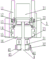
FIG. 1 is a schematic elevational view of the present utility model;
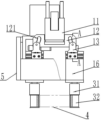
FIG. 2 is a schematic partial cross-sectional view of a side view of the structure of the present utility model;
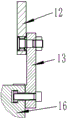
fig. 3 is a cross-sectional view of AA in fig. 2.
In the figure, 11, telescoping cylinder; 12. an adjusting plate; 121. an arc chute; 13. a push plate; 14. a guide rail sliding kinematic pair; 15. a first slider; 16. a mounting base; 21. a driving motor; 22. a gear train; 23. a rotating shaft; 31. adjusting the sleeve; 32. clamping rollers; 4. a bearing ring; 41. upper and lower end surfaces; 42. an outer circle; 43. an inner circle; 5. and (5) fixing the bracket.
Detailed Description
The present utility model will be described in detail with reference to the accompanying drawings. Embodiments of the present utility model are described in detail below, examples of which are illustrated in the accompanying drawings, wherein like or similar reference numerals refer to like or similar elements or elements having like or similar functions throughout. The embodiments described below by referring to the drawings are illustrative only and are not to be construed as limiting the utility model. The terms left, middle, right, upper, lower, etc. in the examples of the present utility model are merely relative concepts or references to the normal use state of the product, and should not be construed as limiting.
The fixture mechanism of the bearing ring superfine grinding machine, as shown in fig. 1 and 2, comprises four clamping rollers 32 which are arranged in parallel and distributed in a rectangular array, wherein at least two clamping rollers 32 are driving rollers, an annular clamping groove is formed in the outer circumference 42 of each clamping roller 32, an included angle between the side wall of the clamping groove and the bottom surface of the clamping groove is an obtuse angle, and the two clamping rollers 32 are slidably arranged on a first sliding block 15 along the direction perpendicular to the axial direction of the clamping roller, and are driven by the first driving mechanism to be close to or far away from each other; the other two clamping rollers 32 are slidably arranged on the second slider along the direction perpendicular to the axial direction of the second slider, and the second driving mechanism drives the two clamping rollers 32 to approach or separate from each other, and the sliding direction of the first two clamping rollers 32 is parallel to the sliding direction of the second two clamping rollers 32; the first sliding block 15 and the second sliding block are fixedly arranged on the fixed bracket 5.
Because the bearing rings 4 with different widths are required to be matched with clamping grooves with different widths, the four clamping rollers 32 are respectively fixedly sleeved on the four rotating shafts 23 and synchronously rotate with the corresponding rotating shafts 23, the four rotating shafts 23 are respectively rotatably installed on the four installation seats 16, the clamping rollers 32 are in sliding fit with the corresponding first sliding blocks 15 or second sliding blocks through the rotating shafts 23 and the installation seats 16, and guide rail sliding kinematic pairs 14 are installed between the installation seats 16 and the corresponding first sliding blocks 15 or second sliding blocks; the rotating shaft 23 is sleeved with an adjusting sleeve 31 in sliding fit with the adjusting sleeve, one end part of the adjusting sleeve 31 is sleeved on one end part of the clamping groove, and the other end part of the adjusting sleeve 31 is tightly clamped on the rotating shaft 23 through a screw tensioning handle. The effective width of the clamping groove is adjusted by adjusting the width of the sleeve 31 sleeved on the clamping groove, so that the clamping groove is adapted to bearing rings 4 with different widths. Because the bearing rings 4 with different diameters are required to be matched by setting the clamping rollers 32 to different distances, for conveniently controlling the clamping rollers 32 to clamp the bearing rings 4, the first driving mechanism and the second driving mechanism have the same structure and respectively comprise a telescopic cylinder 11, an adjusting plate 12 and a push plate 13, the telescopic cylinder 11 can be a telescopic cylinder, the telescopic direction of the telescopic rod in the telescopic cylinder 11 is the same as the axial direction of the rotating shaft 23, the free end of the telescopic rod is fixedly connected with the middle part of the adjusting plate 12, two arc-shaped sliding grooves 121 are respectively arranged at the two end parts of the adjusting plate 12, the two arc-shaped sliding grooves 121 are symmetrically arranged relative to the telescopic rod, one end of each arc-shaped sliding groove 121 is close to the telescopic rod, the other end of each arc-shaped sliding groove 121 is far away from the telescopic rod, the length direction of the adjusting plate 12 is parallel to the length direction of the guide rail sliding kinematic pair 14, the adjusting plate 12 and the clamping rollers 32 are respectively positioned at two opposite sides of the mounting seats 16, the two end parts of the adjusting plate 12 are respectively corresponding to the two corresponding mounting seats 16, the two arc-shaped sliding grooves 121 are respectively arranged at one end parts of the corresponding push plate 13 and the corresponding arc-shaped sliding grooves 13 are respectively arranged in the arc-shaped sliding seats 13; the telescopic rods in the first driving mechanism and the second driving mechanism synchronously move in a telescopic way. The telescopic rod stretches out and draws back to drive push pedal 13 to move in arc spout 121, make push pedal 13 drive mount pad 16 through guide rail sliding motion pair 14 on corresponding first slider 15 and second slider, thereby realize that four centre gripping gyro wheels 32 grasp bearing ring 4. The diameters of the bearing rings 4 in the same batch are the same, the working efficiency is required to be improved by shortening the travel of the telescopic rod, and as shown in fig. 3, a strip-shaped clamping groove with a T-shaped section is formed in the mounting seat 16 at a position corresponding to the push plate 13, the strip-shaped clamping groove is arranged in parallel with the length direction of the guide rail sliding kinematic pair 14, a clamping block is clamped in the strip-shaped clamping groove and is in sliding fit with the strip-shaped clamping groove, and the push plate 13 is fixedly connected with the clamping block through a positioning pin; racks are arranged on the two sides of the mounting seat 16, which are positioned on the strip-shaped clamping grooves, along the length direction of the strip-shaped clamping grooves, and clamping teeth are integrally arranged on the push plate 13 at positions corresponding to the racks, and are meshed with the racks. The relative position of the push plate 13 on the mounting seat 16 is adjusted through the clamping block, the positioning pin and the strip-shaped clamping groove, so that the distance between the clamping rollers 32 is preset, and after the telescopic rod moves in a telescopic manner, the clamping rollers 32 can rapidly clamp the bearing rings 4 with corresponding specifications.
In addition, because the telescopic rods in the first driving mechanism and the second driving mechanism are synchronously telescopic, the two clamping rollers 32 linked with the first driving mechanism are respectively in one-to-one correspondence with the two clamping rollers 32 linked with the second driving mechanism, the relative positions of the corresponding two clamping rollers 32 cannot be changed, so that the clamping rollers 32 are conveniently driven, the corresponding two clamping rollers 32 are linked with the same driving motor 21, the two rotating shafts 23 with fixed relative positions are linked with the same driving motor 21 through the gear trains 22, the driving motor 21 is fixedly arranged on the mounting seats 16 corresponding to the two rotating shafts 23, and the driving motor 21 can be a servo motor. When the first driving mechanism and the second driving mechanism drive the mounting seat 16 to move, the driving motor 21 moves synchronously along with the corresponding mounting seat 16 and drives the corresponding rotating shaft 23 to rotate.
The working principle of the utility model is as follows: referring to fig. 1, when the four clamping rollers 32 are clamped on the inner circle 43 of the bearing ring 4, the grinding tool can grind the outer circle 42 and the upper and lower end faces 41 of the bearing ring 4; as shown in fig. 2, when the four clamping rollers 32 are clamped to the outer ring of the bearing ring 4, the grinding tool can grind the inner circle 43 and the upper and lower end faces 41 of the bearing ring 4.
The foregoing has shown and described the basic principles, principal features and advantages of the utility model. It will be understood by those skilled in the art that the present utility model is not limited to the embodiments described above, and that the above embodiments and descriptions are merely illustrative of the principles of the present utility model, and various changes and modifications may be made without departing from the spirit and scope of the utility model, which is defined in the appended claims. The scope of the utility model is defined by the appended claims and equivalents thereof.
Claims (5)
1. The utility model provides a fixture mechanism of bearing ring superfine grinding machine which characterized in that: the clamping rollers are arranged in parallel and distributed in a rectangular array, at least two of the clamping rollers are driving rollers, annular clamping grooves are formed in the outer circumference of each clamping roller, included angles between the side walls of the clamping grooves and the bottom surfaces of the clamping grooves are obtuse angles, two clamping rollers are arranged on a first sliding block in a sliding mode along the direction perpendicular to the axial direction of the clamping rollers, and the two clamping rollers are driven by a first driving mechanism to be close to or far away from each other; the other two clamping rollers are arranged on the second sliding block in a sliding manner along the direction perpendicular to the axial direction of the second sliding block, and are driven by the second driving mechanism to be close to or far away from each other, and the sliding direction of the first two clamping rollers is parallel to the sliding direction of the second two clamping rollers.
2. The fixture mechanism of a bearing ring superfinishing machine as claimed in claim 1, wherein: the four clamping rollers are fixedly sleeved on the four rotating shafts respectively and rotate synchronously with the corresponding rotating shafts, the four rotating shafts are rotatably installed on the four installation seats respectively, the clamping rollers are in sliding fit with the corresponding first sliding blocks or second sliding blocks through the rotating shafts and the installation seats, and guide rail sliding kinematic pairs are installed between the installation seats and the corresponding first sliding blocks or second sliding blocks; the rotating shaft is sleeved with an adjusting sleeve in sliding fit with the adjusting sleeve, one end part of the adjusting sleeve is sleeved on one end part of the clamping groove, and the other end part of the adjusting sleeve is tightly clamped on the rotating shaft through a screw tensioning handle.
3. The fixture mechanism of a bearing ring superfinishing machine as claimed in claim 2, wherein: the structure of the first driving mechanism and the structure of the second driving mechanism are the same and the first driving mechanism and the second driving mechanism respectively comprise a telescopic cylinder, an adjusting plate and a pushing plate, the telescopic direction of a telescopic rod in the telescopic cylinder is the same as the axial direction of the rotating shaft, the free end of the telescopic rod is fixedly connected with the middle part of the adjusting plate, two arc-shaped sliding grooves are respectively formed in the end parts of the two ends of the adjusting plate, the two arc-shaped sliding grooves are symmetrically arranged relative to the telescopic rod, one end of each arc-shaped sliding groove is close to the telescopic rod, the other end of each arc-shaped sliding groove is far away from the telescopic rod, the length direction of the adjusting plate is parallel to the length direction of a guide rail sliding kinematic pair, the adjusting plate and the clamping rollers are respectively positioned on two opposite sides of the mounting seats, the end parts of the two ends of the adjusting plate are respectively corresponding to the two mounting seats, the pushing plate is respectively arranged between the arc-shaped sliding grooves and the corresponding mounting seats, one end of the pushing plate is slidably mounted in the arc-shaped sliding grooves, and the lower end of the pushing plate is fixedly arranged on the corresponding mounting seat; and the telescopic rods in the first driving mechanism and the second driving mechanism synchronously move in a telescopic way.
4. A fixture mechanism of a bearing ring superfinishing machine as claimed in claim 3, wherein: a strip-shaped clamping groove is formed in the mounting seat at a position corresponding to the push plate, the strip-shaped clamping groove is arranged in parallel with the longitudinal direction of the guide rail sliding kinematic pair, a clamping block is clamped in the strip-shaped clamping groove and is in sliding fit with the strip-shaped clamping groove, and the push plate is fixedly connected with the clamping block through a positioning pin; racks are arranged on the mounting seat and located on two sides of the strip-shaped clamping groove along the length direction of the strip-shaped clamping groove, clamping teeth are integrally arranged on the push plate at positions corresponding to the racks, and the clamping teeth are meshed with the racks.
5. A fixture mechanism of a bearing ring superfinishing machine as claimed in claim 3, wherein: the two rotating shafts with fixed relative positions are linked with the same driving motor through a gear train, and the driving motor is fixedly arranged on the mounting seat corresponding to the two rotating shafts.
Priority Applications (1)
| Application Number | Priority Date | Filing Date | Title |
|---|---|---|---|
| CN202320164279.1U CN219275549U (en) | 2023-02-09 | 2023-02-09 | Clamp mechanism of bearing ring superfine grinding machine |
Applications Claiming Priority (1)
| Application Number | Priority Date | Filing Date | Title |
|---|---|---|---|
| CN202320164279.1U CN219275549U (en) | 2023-02-09 | 2023-02-09 | Clamp mechanism of bearing ring superfine grinding machine |
Publications (1)
| Publication Number | Publication Date |
|---|---|
| CN219275549U true CN219275549U (en) | 2023-06-30 |
Family
ID=86930213
Family Applications (1)
| Application Number | Title | Priority Date | Filing Date |
|---|---|---|---|
| CN202320164279.1U Active CN219275549U (en) | 2023-02-09 | 2023-02-09 | Clamp mechanism of bearing ring superfine grinding machine |
Country Status (1)
| Country | Link |
|---|---|
| CN (1) | CN219275549U (en) |
-
2023
- 2023-02-09 CN CN202320164279.1U patent/CN219275549U/en active Active
Similar Documents
| Publication | Publication Date | Title |
|---|---|---|
| CN111451882B (en) | Five-axis numerical control grinding machine | |
| CN111185806B (en) | Synchronous magnetic grinding device and method for inner and outer surfaces of large barrel part | |
| CN107363691B (en) | Method for realizing simultaneous grinding of two end faces of self-made grinding machine | |
| CN101116947B (en) | Double-ended grinding machine | |
| JP3457268B2 (en) | Apparatus and method for processing the neck of crankshaft shaft | |
| CN114871822A (en) | Centrifugal force-free cutting device | |
| CN108176903A (en) | A kind of high-precision gear grinding machine | |
| CN201089098Y (en) | Paralled surface grinding machine | |
| CN219275549U (en) | Clamp mechanism of bearing ring superfine grinding machine | |
| CN103213056A (en) | Inner bore abrasive belt grinding machine tool and grinding method | |
| CN105290927A (en) | High-precision arc surface grinding device | |
| CN210475752U (en) | Finish machining vertical gear honing machine for high-quality hard tooth surface gear | |
| CN208162782U (en) | A kind of high-precision gear grinding machine | |
| CN116038564A (en) | Clamp mechanism of bearing ring superfine grinding machine | |
| CN217122156U (en) | Pipe cutting supporting and centering device | |
| CN108942441B (en) | Double-sided pot grinding device | |
| CN216577184U (en) | Adjustable grinding device for precision numerical control machine tool | |
| CN210360833U (en) | Main shaft channel grinding device in shaft-connected bearing | |
| CN214109823U (en) | Main shaft hole grinding machine tool | |
| CN112721513B (en) | Annular rotary space three-dimensional carving machine | |
| CN210452095U (en) | Rubber roll grinding aligning sleeve and grinding device for rubber roll | |
| CN210452219U (en) | Special instrument lathe for polishing bearing ring | |
| CN112077681A (en) | Automatic change spiral steel pipe polisher | |
| CN116587085B (en) | Roller double-wheel numerical control grinding machine | |
| CN211414579U (en) | Grinding machine convenient to quick replacement emery wheel |
Legal Events
| Date | Code | Title | Description |
|---|---|---|---|
| GR01 | Patent grant | ||
| GR01 | Patent grant |