CN219272738U - Mixing equipment for graphite powder production - Google Patents
Mixing equipment for graphite powder production Download PDFInfo
- Publication number
- CN219272738U CN219272738U CN202320557662.3U CN202320557662U CN219272738U CN 219272738 U CN219272738 U CN 219272738U CN 202320557662 U CN202320557662 U CN 202320557662U CN 219272738 U CN219272738 U CN 219272738U
- Authority
- CN
- China
- Prior art keywords
- mixing
- graphite powder
- lifting
- fixedly arranged
- gear
- Prior art date
- Legal status (The legal status is an assumption and is not a legal conclusion. Google has not performed a legal analysis and makes no representation as to the accuracy of the status listed.)
- Active
Links
Images


Classifications
-
- Y—GENERAL TAGGING OF NEW TECHNOLOGICAL DEVELOPMENTS; GENERAL TAGGING OF CROSS-SECTIONAL TECHNOLOGIES SPANNING OVER SEVERAL SECTIONS OF THE IPC; TECHNICAL SUBJECTS COVERED BY FORMER USPC CROSS-REFERENCE ART COLLECTIONS [XRACs] AND DIGESTS
- Y02—TECHNOLOGIES OR APPLICATIONS FOR MITIGATION OR ADAPTATION AGAINST CLIMATE CHANGE
- Y02E—REDUCTION OF GREENHOUSE GAS [GHG] EMISSIONS, RELATED TO ENERGY GENERATION, TRANSMISSION OR DISTRIBUTION
- Y02E60/00—Enabling technologies; Technologies with a potential or indirect contribution to GHG emissions mitigation
- Y02E60/10—Energy storage using batteries
Abstract
The utility model belongs to the field of graphite processing, in particular to mixing equipment for graphite powder production, which comprises a mixing box, wherein a lifting table is slidably arranged between the inner walls of the left side and the right side of the mixing box, a mixing cylinder is arranged at the top of the lifting table, and graphite powder raw materials are arranged on the inner side of the mixing cylinder; the lifting assembly is arranged on the mixing box and the lifting table; and a mixing assembly mounted on the mixing tank. The utility model has reasonable design, can keep the fixation and lifting actions of the mixing drum synchronous and consistent, can avoid manual operation by electric control, has simple operation, can ensure that the preparation time of graphite powder before mixing is shorter, can ensure that the mixing speed is improved, further can ensure that the mixing efficiency is improved, can realize full mixing of graphite powder raw materials by internal and external reverse rotation stirring and mixing, further can ensure that the mixing effect of graphite powder is better, and ensures that the production quality of the graphite powder is higher.
Description
Technical Field
The utility model relates to the technical field of graphite processing, in particular to mixing equipment for graphite powder production.
Background
Graphite belongs to an allotrope of carbon, is gray black, is an opaque solid, has stable chemical property, is corrosion-resistant, and is not easy to react with medicaments such as acid, alkali and the like, and a mixing device is required to mix the components of the graphite raw material during production;
the utility model discloses a mixing equipment for graphite powder production, including the base and the loading board of base top, two sets of electric putter are vertically installed to the inside of base, electric putter's top is connected with the loading board, the both sides of base up end are vertical to be connected with the stand, the top of stand is connected with the roof, the lower surface fixedly connected with case lid of roof, the inside stirring frame that is equipped with of case lid, the motor that upper surface mounting of roof is connected with the stirring frame, be equipped with the blending tank on the loading board, the blending tank is placed on the loading board, is connected fixedly through stopper and spacing groove, makes blending tank and case lid be connected after the loading board rises, and the blending tank is easily dismantled, conveniently takes;
if this kind of mixing apparatus for graphite powder production can have two problems when using in the comparison document, firstly it needs manual operation when realizing to mixing drum centre gripping, troublesome operation, the rethread actuating device makes the mixing drum go up and down after confirming to fix, this process can probably lead to graphite powder the preparation time before mixing longer for mixing speed slows down, and then lead to mixing efficiency lower, secondly it only drives the puddler through the link when mixing the graphite raw materials and rotates inside the mixing drum, the lateral length of puddler is less, can lead to graphite raw materials's mix inadequately when stirring, and then lead to graphite powder's mixed effect relatively poor, make graphite powder's production quality lower, consequently we propose a mixing apparatus for graphite powder production.
Disclosure of Invention
The utility model aims to solve the defects in the prior art, and provides mixing equipment for producing graphite powder.
In order to achieve the above purpose, the present utility model adopts the following technical scheme:
a mixing apparatus for graphite powder production, comprising:
the graphite powder mixing device comprises a mixing box, wherein a lifting table is slidably arranged between the inner walls of the left side and the right side of the mixing box, a mixing cylinder is arranged at the top of the lifting table, and graphite powder raw materials are arranged on the inner side of the mixing cylinder;
the lifting assembly is arranged on the mixing box and the lifting table;
and a mixing assembly mounted on the mixing tank.
Preferably, the lifting assembly comprises a lifting motor, a driving shaft, a lifting screw rod, a bevel gear, a thread bush, a swivel base, a bidirectional screw rod, a first belt pulley, a second belt pulley, a belt and a clamping block, wherein a mounting frame is fixedly arranged at the bottom of the lifting table, the lifting motor is fixedly arranged on the inner wall of the bottom of the mounting frame, the driving shaft is fixedly arranged at the output end of the lifting motor, the lifting screw rod is fixedly arranged at the bottom of the lifting table, the bevel gear is respectively arranged at the outer sides of the driving shaft and the thread bush, the bevel gear is meshed with the bevel gear, the thread bush is in threaded connection with the outer sides of the lifting screw rod, the thread bush is rotatably arranged at the middle of the inner wall of the bottom of the mixing box, the swivel base is fixedly arranged at the four corners of the bottom of the lifting table, the bidirectional screw rod is rotatably arranged between the inner sides of the swivel base, the first belt pulley is fixedly arranged at the outer sides of the driving shaft and the lifting screw rod, the second belt pulley is fixedly arranged at the outer left side of the bidirectional screw rod, the belt is respectively tensioned on the outer sides of the two first belt pulleys and the outer sides of the two second belt pulleys, the clamping block is in threaded connection with the two lateral sides of the bidirectional screw rod, the clamping block is respectively, and the clamping block is slidably arranged at the top of the lifting table.
Preferably, sliding grooves are formed in four corners of the top of the lifting table, and the width of each sliding groove is matched with the width of each clamping block.
Preferably, the second pulley is located to the left of the swivel mount and the first pulley is located to the right of the left Fang Zhuai.
Preferably, the rotation centers of the thread sleeve, the lifting screw rod and the right bevel gear are all positioned on the same central axis, a thread termination line is arranged on the outer side of the thread sleeve, and a lower thread termination line is positioned above the upper surface of the bevel gear.
Preferably, the mixing assembly comprises a rotating motor, a central shaft, a connecting shaft, an inner gear ring, a rotating frame, a central gear, a connecting gear, a first stirring rod, a second stirring rod and a dust cover, wherein the rotating motor is fixedly arranged at the top of the mixing box, the central shaft is fixedly arranged at the output end of the rotating motor, the connecting shaft is rotatably arranged at the left side and the right side of the inner wall of the top of the mixing box, the rotating frame is rotatably arranged at the inner wall of the top of the mixing box, the inner gear ring is fixedly arranged at the inner upper side of the rotating frame, the central gear is fixedly arranged at the outer side of the central shaft, the connecting gear is fixedly arranged at the outer side of the connecting shaft, the connecting gear is respectively meshed with the central gear and the inner gear ring, the first stirring rod is fixedly arranged at one circle of the inner side of the rotating frame, and the second stirring rod is fixedly arranged at one circle of the outer side of the central shaft.
Preferably, the first stirring rod and the second stirring rod are sequentially arranged from top to bottom, and the first stirring rod and the second stirring rod are arranged in a staggered manner.
Preferably, the top of the rotating frame is provided with an annular sliding block, and the cross section of the annular sliding block is in a convex shape.
Compared with the prior art, the utility model has the beneficial effects that:
(1) According to the mixing equipment for producing the graphite powder, through the lifting assembly, the fixing and lifting actions of the mixing drum can be kept synchronous and consistent, manual operation can be avoided through electric control, the operation is simple, the preparation time of the graphite powder before mixing is short, the mixing speed is improved, and the mixing efficiency is improved.
(2) According to the mixing equipment for producing the graphite powder, through the mixing assembly, the mixing equipment for producing the graphite powder can fully mix the graphite powder raw materials through internal and external counter-rotation stirring and mixing, so that the mixing effect of the graphite powder is good, and the production quality of the graphite powder is high.
Drawings
Fig. 1 is a schematic perspective view of a mixing device for graphite powder production according to the present utility model;
FIG. 2 is a schematic cross-sectional view of a mixing apparatus for graphite powder production according to the present utility model;
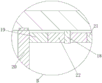
FIG. 3 is an enlarged schematic view of the portion A in FIG. 2;
fig. 4 is an enlarged schematic view of a portion B in fig. 2.
In the figure: 1. a mixing box; 2. a lifting table; 3. a mixing drum; 4. graphite powder raw material; 5. a lifting motor; 6. a driving shaft; 7. lifting the screw rod; 8. bevel gears; 9. a thread sleeve; 10. rotating base; 11. a two-way screw rod; 12. a first pulley; 13. a second pulley; 14. a belt; 15. a clamping block; 16. a rotating electric machine; 17. a central shaft; 18. a connecting shaft; 19. an inner gear ring; 20. a rotating frame; 21. a sun gear; 22. a connecting gear; 23. a first stirring rod; 24. a second stirring rod; 25. a dust cover.
Detailed Description
The following description of the embodiments of the present utility model will be made clearly and completely with reference to the accompanying drawings, in which it is apparent that the embodiments described are only some embodiments of the present utility model, but not all embodiments.
Examples
Referring to fig. 1-4, a mixing device for graphite powder production comprises a mixing box 1, a lifting assembly and a mixing assembly, wherein a lifting table 2 is slidably installed between the inner walls of the left side and the right side of the mixing box 1, the lifting table 2 can conveniently drive a mixing cylinder 3 to enter a dust-proof sleeve 25, dust in the mixing process is prevented from diffusing, the top of the lifting table 2 is provided with the mixing cylinder 3, the inner side of the mixing cylinder 3 is provided with a graphite powder raw material 4, the lifting assembly is installed on the mixing box 1 and the lifting table 2, and the mixing assembly is installed on the mixing box 1.
In this embodiment, the bottom fixed mounting of elevating platform 2 has the mounting bracket, elevating motor 5 fixed mounting is in the bottom inner wall of mounting bracket, driving shaft 6 fixed mounting is in the output of elevating motor 5, elevating screw rod 7 fixed mounting is in the bottom of elevating platform 2, bevel gear 8 sets up the outside at driving shaft 6 and thread bush 9 respectively, left side bevel gear 8 fixed mounting is in the outside of driving shaft 6, right side bevel gear 8 rotates the top of installing at the mounting bracket, right side bevel gear 8 slidable mounting is in the outside of thread bush 9, when can realizing that the mounting bracket rises along with elevating platform 2 like this, bevel gear 8 still can guarantee the meshing, bevel gear 8 intermeshing, thread bush 9 threaded connection is in the outside of elevating screw rod 7, thread bush 9 rotation is installed in the bottom inner wall intermediate department of mixing box 1, swivel mount 10 fixed mounting is in the bottom four corners of elevating platform 2, bidirectional screw rod 11 rotates and installs between the inboard of swivel mount 10 in the left and right sides, first band pulley 12 is fixed mounting in the outside of driving shaft 6 and elevating screw rod 7 respectively, second band pulley 13 fixed mounting is in the outside left side of bidirectional screw rod 11, belt 14 tensioning sets up the outside at two first band pulley 12 and two band pulley blocks 13 and two band pulley blocks 15 respectively, can carry out clamping groove 15 in the clamping groove 15 outside the clamping groove 3 in the left and right sides, clamping groove 15 is equipped with the clamping groove in the clamping groove 3 in the side, the clamping groove is equipped with the clamping groove in the two sides 3, and the clamping groove is equipped with clamping groove in the clamping groove.
In this embodiment, the rotating motor 16 is fixedly installed at the top of the mixing box 1, the central shaft 17 is fixedly installed at the output end of the rotating motor 16, the connecting shaft 18 is rotatably installed at the left side and the right side of the inner wall of the top of the mixing box 1, the rotating frame 20 is rotatably installed at the inner wall of the top of the mixing box 1, the inner gear ring 19 is fixedly installed at the inner upper side of the rotating frame 20, the rotating frame 20 and the central shaft 17 can be made to rotate in opposite directions through the meshing of the inner gear ring 19 and the connecting gear 22, the central gear 21 is fixedly installed at the outer side of the central shaft 17, the connecting gear 22 is fixedly installed at the outer side of the connecting shaft 18, the connecting gear 22 is respectively meshed with the central gear 21 and the inner gear ring 19, the first stirring rod 23 is fixedly installed at the inner side of the rotating frame 20 for a circle, the second stirring rod 24 is fixedly installed at the outer side of the central shaft 17 for a circle, the first stirring rod 23 and the second stirring rod 24 are sequentially arranged from top to bottom, the top of the rotating frame 20 is provided with an annular sliding block, the cross section of the annular sliding block is convex, the inner wall of the mixing box 1 is provided with an annular sliding block, the dimension of the sliding block is matched with the annular ring groove, and the size of the annular groove is not suitable for rotating the mixing box 1, and the mixing box can be rotated stably.
Through the structure, the mixing equipment for producing the graphite powder can keep the synchronous and consistent fixing and lifting actions of the mixing drum 3, the electric control can avoid manual operation, the operation is simple, the preparation time of the graphite powder before mixing is shorter, the mixing speed is improved, the mixing efficiency is improved, the mixing of the graphite powder raw materials 4 can be fully realized through internal and external reverse rotation stirring and mixing, the mixing effect of the graphite powder is better, the production quality of the graphite powder is higher, the equipment is firstly connected with an external power supply, the graphite powder raw materials 4 are placed in the mixing drum 3, the mixing drum 3 is placed at the top of the lifting table 2, the lifting motor 5 is controlled to work through the controller, the lifting motor 5 drives the first belt pulley 12 and the left bevel gear 8 to rotate through the driving shaft 6, the left bevel gear 8 drives the right bevel gear 8 to rotate through engagement, the right bevel gear 8 drives the lifting screw rod 7 to rise through threaded engagement when rotating, the lifting screw rod 7 drives the lifting table 2 to rise, meanwhile, the right bevel gear 8 is driven to slide outside the threaded sleeve 9 through the mounting frame and the connecting piece, simultaneously, the first belt pulley 12, the second belt pulley 13 and the belt 14 cooperate to drive the two bidirectional screw rods 11 to rotate, the two bidirectional screw rods 11 cooperate to drive the two clamping blocks 15 to move in opposite directions until clamping the mixing drum 3 until the mixing drum 3 is clamped, at the moment, the top of the mixing drum 3 is positioned at the inner side of the dust cover 25, the rotating motor 16 is controlled by the controller to work, the rotating motor 16 drives the second stirring rod 24 and the central gear 21 to rotate through the central gear 21 and the connecting gear 22 to engage to drive the connecting gear 22 to rotate, and then the rotating frame 20 is driven to rotate by being meshed with the inner gear ring 19 through the connecting gear 22, and then the rotatable frame 20 can drive the first stirring rod 23 to rotate, so that the first stirring rod 23 and the second stirring rod 24 are used for reversely stirring and mixing the graphite powder raw material 4.
The mixing equipment for producing the graphite powder provided by the utility model is described in detail above. The principles and embodiments of the present utility model have been described herein with reference to specific examples, which are intended to be merely illustrative of the methods of the present utility model and their core ideas. It should be noted that it will be apparent to those skilled in the art that various modifications and adaptations of the utility model can be made without departing from the principles of the utility model and these modifications and adaptations are intended to be within the scope of the utility model as defined in the following claims.
Claims (8)
1. Mixing apparatus for graphite powder production, characterized by comprising:
the graphite powder mixing device comprises a mixing box (1), wherein a lifting table (2) is slidably arranged between the inner walls of the left side and the right side of the mixing box (1), a mixing cylinder (3) is arranged at the top of the lifting table (2), and graphite powder raw materials (4) are arranged on the inner side of the mixing cylinder (3);
the lifting assembly is arranged on the mixing box (1) and the lifting table (2);
a mixing assembly mounted on a mixing box (1).
2. The mixing device for producing graphite powder according to claim 1, wherein the lifting assembly comprises a lifting motor (5), a driving shaft (6), a lifting screw rod (7), a bevel gear (8), a threaded sleeve (9), a swivel base (10), a bidirectional screw rod (11), a first belt wheel (12), a second belt wheel (13), a belt (14) and a clamping block (15), a mounting frame is fixedly arranged at the bottom of the lifting table (2), the lifting motor (5) is fixedly arranged on the inner wall of the bottom of the mounting frame, the driving shaft (6) is fixedly arranged at the output end of the lifting motor (5), the lifting screw rod (7) is fixedly arranged at the bottom of the lifting table (2), the bevel gears (8) are respectively arranged at the outer sides of the driving shaft (6) and the threaded sleeve (9), the bevel gears (8) are meshed with each other, the threaded sleeve (9) is in threaded connection with the outer side of the lifting screw rod (7), the threaded sleeve (9) is rotatably arranged at the middle of the bottom inner wall of the lifting box (1), the swivel base (10) is fixedly arranged at the bottom of the four corners (2), the bevel gear (8) is fixedly arranged at the inner sides of the bottom of the lifting table (11), the two sides of the driving shaft (6) are fixedly arranged at the outer sides of the two sides of the lifting screw rod (12 respectively, the second belt wheels (13) are fixedly arranged on the left side of the outer side of the bidirectional screw rod (11), the belt (14) is respectively tensioned and arranged on the outer sides of the two first belt wheels (12) and the two second belt wheels (13), the clamping blocks (15) are in threaded connection on the left side and the right side of the outer side of the bidirectional screw rod (11), and the clamping blocks (15) are slidably arranged on the top of the lifting table (2).
3. The mixing device for graphite powder production according to claim 2, wherein sliding grooves are formed in four corners of the top of the lifting table (2), and the width of the sliding grooves is matched with the width of the clamping blocks (15).
4. A mixing device for the production of graphite powder as claimed in claim 3, characterized in that the second pulley (13) is located to the left of the swivel mount (10) and the first pulley (12) is located to the right of the left Fang Zhuai (10).
5. The mixing device for graphite powder production according to claim 4, wherein the rotation centers of the thread bush (9), the lifting screw rod (7) and the right bevel gear (8) are all located on the same central axis, a thread stop line is arranged on the outer side of the thread bush (9), and a lower thread stop line is located above the upper surface of the bevel gear (8).
6. The mixing device for producing graphite powder according to claim 1, wherein the mixing assembly comprises a rotating motor (16), a central shaft (17), a connecting shaft (18), an inner gear ring (19), a rotating frame (20), a central gear (21), a connecting gear (22), a first stirring rod (23), a second stirring rod (24) and a dust-proof sleeve (25), the rotating motor (16) is fixedly arranged at the top of the mixing box (1), the central shaft (17) is fixedly arranged at the output end of the rotating motor (16), the connecting shaft (18) is rotatably arranged at the left side and the right side of the inner wall of the top of the mixing box (1), the rotating frame (20) is rotatably arranged at the inner wall of the top of the mixing box (1), the inner gear ring (19) is fixedly arranged at the upper inner side of the rotating frame (20), the central gear (21) is fixedly arranged at the outer side of the central shaft (17), the connecting gear (22) is fixedly arranged at the outer side of the connecting shaft (18), the connecting gear (22) is respectively meshed with the central gear (21) and the inner gear ring (19), and the first stirring rod (23) is fixedly arranged at the inner side of the first stirring rod (17) in a circle.
7. The mixing device for graphite powder production according to claim 6, wherein the first stirring rod (23) and the second stirring rod (24) are sequentially arranged from top to bottom, and the first stirring rod (23) and the second stirring rod (24) are staggered.
8. The mixing device for graphite powder production according to claim 7, wherein the top of the rotating frame (20) is provided with an annular slider, and the cross-sectional shape of the annular slider is convex.
Priority Applications (1)
| Application Number | Priority Date | Filing Date | Title |
|---|---|---|---|
| CN202320557662.3U CN219272738U (en) | 2023-03-21 | 2023-03-21 | Mixing equipment for graphite powder production |
Applications Claiming Priority (1)
| Application Number | Priority Date | Filing Date | Title |
|---|---|---|---|
| CN202320557662.3U CN219272738U (en) | 2023-03-21 | 2023-03-21 | Mixing equipment for graphite powder production |
Publications (1)
| Publication Number | Publication Date |
|---|---|
| CN219272738U true CN219272738U (en) | 2023-06-30 |
Family
ID=86919225
Family Applications (1)
| Application Number | Title | Priority Date | Filing Date |
|---|---|---|---|
| CN202320557662.3U Active CN219272738U (en) | 2023-03-21 | 2023-03-21 | Mixing equipment for graphite powder production |
Country Status (1)
| Country | Link |
|---|---|
| CN (1) | CN219272738U (en) |
-
2023
- 2023-03-21 CN CN202320557662.3U patent/CN219272738U/en active Active
Similar Documents
| Publication | Publication Date | Title |
|---|---|---|
| CN206996420U (en) | A kind of convertible high-speed mixer | |
| CN219272738U (en) | Mixing equipment for graphite powder production | |
| CN214088446U (en) | Sealed effectual green plum wine processingequipment | |
| CN213132936U (en) | Feed mixer based on differential stirring | |
| CN219682324U (en) | Stirring and dispersing equipment for feed additive production | |
| CN211302838U (en) | High-efficient feed additive mixing arrangement | |
| CN217725294U (en) | Quartz stone processing rabbling mechanism | |
| CN216877923U (en) | Sodium glucoheptonate recrystallization reation kettle | |
| CN217989295U (en) | Full-automatic mixing reactor for polypropylene, grafting auxiliary agent and polar compound | |
| CN211941558U (en) | Rubber plug rubber raw material mixing device | |
| CN215196604U (en) | Toothpaste production stirring mixing arrangement | |
| CN213353051U (en) | High-efficient mixer | |
| CN212092057U (en) | A homogenizing device for producing industrial emulsifier | |
| CN210385561U (en) | Battery pole material mixer | |
| CN214486682U (en) | Planetary wheel-grinding mixer | |
| CN216856497U (en) | Homogeneity mixes liquid device for cosmetics production | |
| CN208161449U (en) | A kind of mixing plant applied to high molecular material engineering | |
| CN217016360U (en) | Nonmetal mineral powder modifying machine | |
| CN216260696U (en) | Reactor for aluminum phosphide production | |
| CN219855397U (en) | High-performance polypropylene stirring tank with good stability | |
| CN216860251U (en) | Novel multiple rotatory silica gel mixing roll | |
| CN213556724U (en) | Raw material stirring device for production of drum brake friction plate | |
| CN219500402U (en) | Butter whipping device | |
| CN213966281U (en) | A agitating unit for food production | |
| CN213726100U (en) | Double-shaft stirrer for producing anti-dripping agent |
Legal Events
| Date | Code | Title | Description |
|---|---|---|---|
| GR01 | Patent grant | ||
| GR01 | Patent grant |