Portable field operations portable charging device
Technical Field
The utility model belongs to the technical field of mobile power supplies, and particularly relates to a portable field mobile charging device.
Background
The operation of electronic products such as mobile phones and electric appliances needs to be powered, and although the power is conveniently taken in the coverage area of a power grid, the power utilization becomes a great difficulty in the field without the coverage of the power grid.
The mobile power supply makes the field solve the power consumption problem a charging power supply unit, and current mobile power supply does not dispose field charging device mostly, and in case its inside electric quantity is spent, can't reuse before recharging for mobile power supply's live time receives very big restriction under the field environment, and partial mobile power supply is equipped with the photovoltaic board and can charges in the field, nevertheless because the photovoltaic board exposes outside, is easily collided and leads to damaging, influences the use experience.
In summary, the present utility model provides a portable field mobile charging device to solve the above problems.
Disclosure of Invention
In order to solve the technical problems, the utility model provides a portable field mobile charging device, which aims to solve the problems that most field charging devices in the prior art are limited in use and are easy to damage although the service time of the field charging devices is prolonged by a photovoltaic plate.
The utility model provides a portable field operations portable charging device, includes the main part, the mounting groove has been seted up at the top of main part, the main part top articulates in one side of mounting groove has first protective cover, the mounting groove is kept away from the top of first protective cover one side inner wall and is articulated to have the second visor, the position department that is close to the second visor in the mounting groove articulates there is the photovoltaic board, the both sides of the photovoltaic board other end all are equipped with the connecting axle, the bilateral symmetry of first protective cover bottom is equipped with two connecting blocks, two all seted up the spout on the connecting block, the connecting axle of photovoltaic board both sides penetrates respectively in two spouts, and penetrates the surface of one end and all be equipped with the slider, all slide between slider and the spout links to each other, the threaded rod is installed to the below of photovoltaic board to the mounting groove inside, the surface mounting of threaded rod has the movable block, the both ends of movable block all are connected with first connecting rod, and the other end of two connecting rods rotate with the both sides of photovoltaic board respectively and link to each other.
Further, the two sides of the photovoltaic panel are also connected with second connecting rods, and the other ends of the second connecting rods are rotationally connected with one side, close to the photovoltaic panel, of the second protective cover.
Further, the movable block is in threaded connection with the threaded rod.
Further, a knob is arranged on one side of the surface of the main body, and the knob is in transmission connection with the threaded rod.
Further, the surface of the main body far away from one side of the knob is provided with a display screen, a power supply socket, a USB socket and a control button.
Further, a storage battery and a control circuit board are arranged in the main body.
Further, handles are arranged at the tops of the surfaces of two opposite sides of the main body, and idler wheels are arranged at four corners of the bottom of the main body.
Compared with the prior art, the utility model has the following beneficial effects:
1. according to the utility model, when the photovoltaic panel is needed, the light energy can be converted into the electric energy and stored in the storage battery, so that the service time of the photovoltaic panel is prolonged, and meanwhile, when the photovoltaic panel is not needed, the first protective cover and the second protective cover are used for sealing the photovoltaic panel in the mounting groove for protection through the connecting rod system, so that the photovoltaic panel is prevented from being damaged due to collision.
2. The portable and movable trolley can be respectively improved in portability and mobility through the handles and the rollers, and is convenient to carry and move.
Drawings
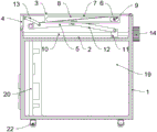
FIG. 1 is a schematic perspective view of a photovoltaic panel of the present utility model when not in use;
FIG. 2 is a schematic perspective view of the photovoltaic panel of the present utility model in use;
FIG. 3 is a schematic plan cross-sectional view of the photovoltaic panel of the present utility model when not in use;
fig. 4 is a schematic plan sectional view of the photovoltaic panel of the present utility model in use.
In the figure:
1. a main body; 2. a mounting groove; 3. a first protective cover; 4. a second protective cover; 5. a photovoltaic panel; 6. a connecting shaft; 7. a connecting block; 8. a chute; 9. a slide block; 10. a threaded rod; 11. a moving block; 12. a first link; 13. a second link; 14. a knob; 15. a display screen; 16. a power supply socket; 17. a USB socket; 18. a control button; 19. a storage battery; 20. a control circuit board; 21. a handle; 22. and a roller.
Detailed Description
Embodiments of the present utility model are described in further detail below with reference to the accompanying drawings and examples. The following examples are illustrative of the utility model but are not intended to limit the scope of the utility model.
As shown in fig. 1-4, the utility model provides a portable field mobile charging device, which comprises a main body 1, the top of the main body 1 is provided with a mounting groove 2, one side of the top of the main body 1, which is arranged on the mounting groove 2, is hinged with a first protection cover 3, the top of the inner wall of one side, which is far away from the first protection cover 3, of the mounting groove 2 is hinged with a second protection cover 4, the photovoltaic plate 5 is sealed inside the mounting groove 2 through the first protection cover 3 and the second protection cover 4, so that the photovoltaic plate 5 is protected from collision damage, a photovoltaic plate 5 is hinged in the mounting groove 2 at a position close to the second protection cover 4, a storage battery 19 inside the main body 1 is charged through the photovoltaic plate 5, the purpose of prolonging service time is achieved, two sides of the other end of the photovoltaic plate 5 are respectively provided with a connecting shaft 6, two connecting blocks 7 are symmetrically arranged on two sides of the bottom of the first protection cover 3, two connecting shafts 6 on two sides of the connecting blocks 7 are respectively penetrated into the two sliding grooves 8, the surfaces penetrating into one end of the two sliding grooves 9 are respectively sleeved with the sliding blocks 9, the two sliding blocks 10 are respectively installed on the two sides of the connecting rods 10, and the two connecting rods 10 are respectively connected with the two sliding blocks 10 and are respectively installed on the two sides of the connecting rods 10 and are connected with the two sliding blocks 10.
The two sides of the photovoltaic panel 5 are further connected with a second connecting rod 13, the other ends of the second connecting rods 13 are rotatably connected with one side, close to the photovoltaic panel 5, of the second protective cover 4, and when the photovoltaic panel 5 stands up, the second connecting rods 13 drive the second protective cover 4 to outwards overturn by a certain angle, so that shielding of the photovoltaic panel 5 is reduced, and energy conversion efficiency of the photovoltaic panel 5 is improved.
The moving block 11 is in threaded connection with the threaded rod 10, and when the threaded rod 10 rotates, the moving block 11 moves on the surface of the threaded rod 10.
The knob 14 is installed on one side of the surface of the main body 1, the knob 14 is in transmission connection with the threaded rod 10, and the threaded rod 10 is driven to rotate by the knob 14.
Wherein, the surface that main part 1 was kept away from knob 14 one side is provided with display screen 15, power supply socket 16, USB socket 17 and control button 18, can show power consumption condition and residual capacity information through display screen 15, and power supply socket 16 and then USB socket 17 conveniently supply power to different electrical appliances and electronic products, and control button 18 conveniently controls power supply switch.
Wherein, the main body 1 is internally provided with a storage battery 19 and a control circuit board 20, the storage battery 19 is used for storing electric energy, and the control circuit board 20 is responsible for controlling the operation of each electric structure.
The lifting handles 21 are arranged at the tops of the two opposite side surfaces of the main body 1, the rolling wheels 22 are arranged at four corners of the bottom of the main body 1, and the portability and the mobility of the portable bicycle are respectively improved through the lifting handles 21 and the rolling wheels 22, so that the portable bicycle is convenient to carry and move.
The specific working principle is as follows:
when the portable photovoltaic protection cover is used, the threaded rod 10 can be driven to rotate through the rotary knob 14 when needed, the threaded rod 10 is connected with the movable block 11 through threads, the movable block 11 moves towards one side of the second protection cover 4, so that the angle of the first connecting rod 12 is changed, the photovoltaic panel 5 is erected, when the photovoltaic panel 5 is erected, the first protection cover 3 rotates downwards through the sliding chute 8 on the bottom connecting block 7 and the sliding block 9 mounted on the photovoltaic panel 5 through the connecting shaft 6 and under the action of the sliding block 9, so that the photovoltaic panel 5 is exposed, the photovoltaic panel 5 charges the storage battery 19 in the main body 1, the purpose of prolonging the service time is achieved, the second connecting rod 13 drives the second protection cover 4 to outwards overturn a certain angle when the photovoltaic panel 5 is erected, the energy conversion efficiency of the photovoltaic panel 5 is improved, when the threaded rod is not needed to be used for charging, the photovoltaic panel 5 is rotated downwards through the reverse rotation 10, the photovoltaic panel 5 is enabled to be protected, the first protection cover 3 and the second protection cover 4 are enabled to be in collision with the portable protection cover 2 through the sliding block 9, the portable protection cover is convenient to carry the portable protection cover, and the portable protection cover can be prevented from being damaged by the portable protection cover 2, and the portable protection cover can be mounted inside the portable protection cover 2 through the photovoltaic protection cover is convenient to be carried by the portable protection cover 2, and the portable protection cover is convenient to be carried by the portable protection cover and the portable protection cover is protected.
The embodiments of the present utility model have been shown and described for the purpose of illustration and description, it being understood that the above embodiments are illustrative and not to be construed as limiting the utility model, and that variations, modifications, alternatives and variations may be made therein by one of ordinary skill in the art without departing from the scope of the utility model.